Flex BMR456 User manual

Evaluation board for digital IBC
USER GUIDE for BMR456, BMR457, BMR458
ROA 1283835

User guide evaluation board BMR45x
2023-12-05
2 (14)
Contents
1Introduction.......................................................................................3
1.1 How to contact Flex Power Modules ..............................................3
2Schematics........................................................................................4
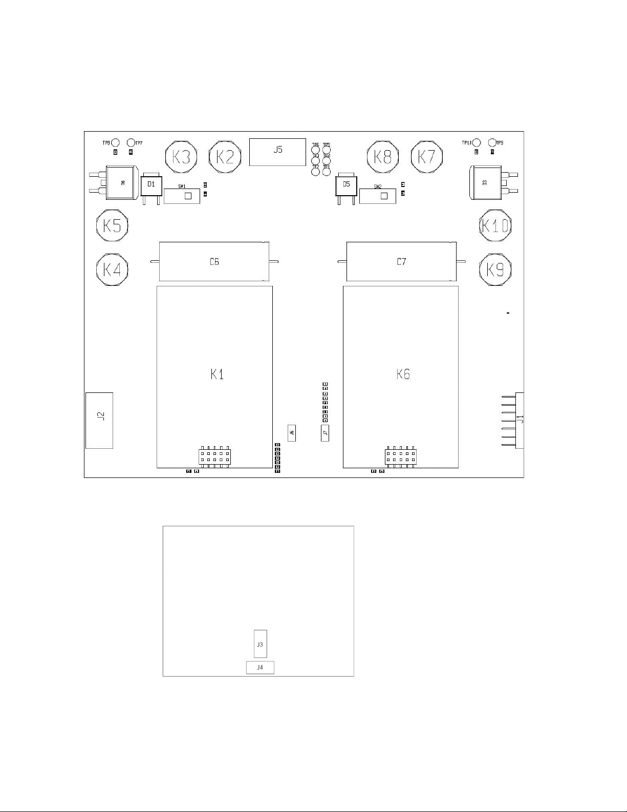
3Component layout ...........................................................................5
4Power up ...........................................................................................6
4.1 Power up/down instructions ............................................................6
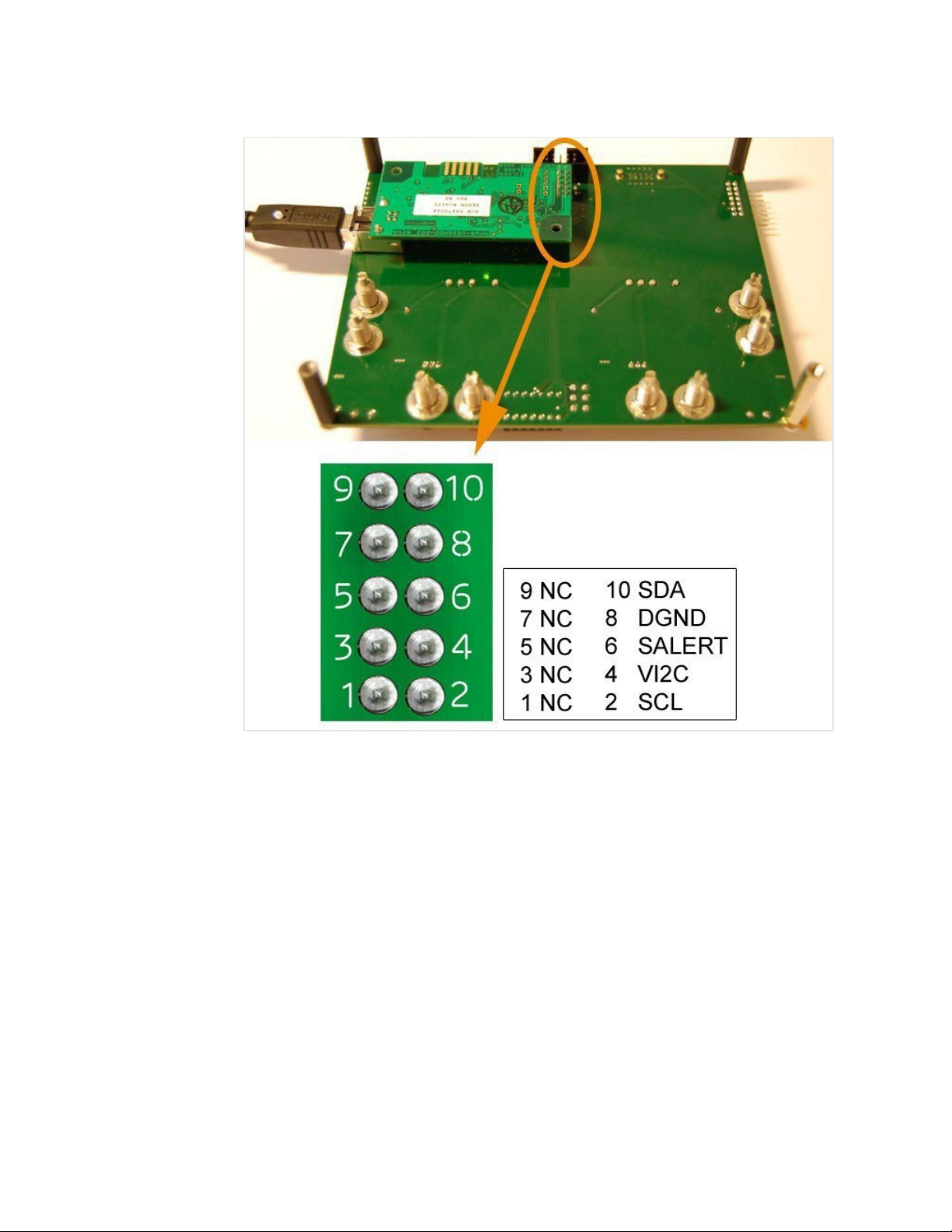
4.1.1 Power Supply Connection ...............................................................6
4.1.2 Power-up instruction:........................................................................8
4.1.3 Power-down instruction:...................................................................9
4.2 Jumper positions ...............................................................................9
4.2.1 Default settings .................................................................................9
4.2.2 Jumper settings for BMR 456/457...................................................10
5Change of series resistors for the LEDs ..........................................11
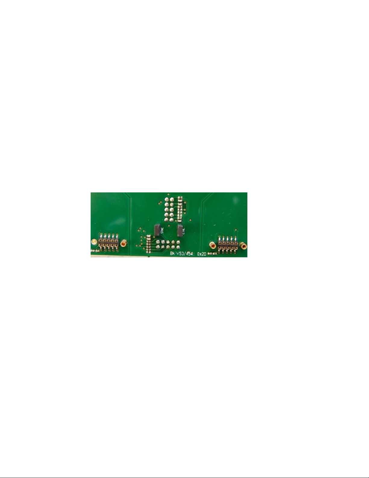
5.1 Change of LED series resistors R3 and R4 in position 0x2B ...........11
5.1.1 Change of LED series resistors R7 and R8 in position 0x2D...........12
6Dimensions ......................................................................................13
7Contact us.......................................................................................14

User guide evaluation board BMR45x
2023-12-05
3 (14)
1Introduction
This User Guide provides a brief introduction and instruction on how to use
the evaluation board ROA 1283835 together with BMR456, BMR457 and
BMR458.
1.1 How to contact Flex Power Modules
For general questions or interest in our products, please visit our website or
contact your local sales representative.
Flexpowermodules.com

User guide evaluation board BMR45x
2023-12-05
4 (14)
2Schematics
Below is the top level schematics of ROA 1283835.
For BMR456/457 the address is in this position 0x35 and 0x36.
Figure 1: Schematics of ROA 1283835

User guide evaluation board BMR45x
2023-12-05
5 (14)
3Component layout
In Figure 2.1 and 2.2 the component layout is shown
Figure 2.1: Top side component layout of ROA 1283835
Figure 2.2: Bottom side component layout of ROA 1283835

User guide evaluation board BMR45x
2023-12-05
6 (14)
4Power up
4.1 Power up/down instructions
This section of the document describes how to connect power supply for
different cases in order to avoid mistake during measurements.
The jumpers that you need shall be mounted before power-up. See
Section 3.2 for information about jumper positions.
4.1.1 Power Supply Connection
Add the 48V DC power to one or two pairs ot the “-IN” and “+IN”
connectors (see Fig 3.1).
Figure 3.1a: Connect 48V between the “-IN” and “+IN” DC power connectors located on
the same side of the board (see orange rectangles)
There are two RC switches on the ROA 128 3835 board, one for each IBC converter position.
Fig 3.2 shows one of the two RC switches in “Off” position.
Figure 3.2 One of the two RC switches in “Off” position

User guide evaluation board BMR45x
2023-12-05
7 (14)
Figure 3.3a and Figure 3.4b show the connection of 2 types of USB-to-PMBus adapters
.
Figure 3.3a: Connection of the Flex Power Modules KEP 910 17 PMBus-to-USB adapter
(connector is found on the back side of the ROA 1283835 board)

User guide evaluation board BMR45x
2023-12-05
8 (14)
Figure 3.3b: Connection of the Intersil ZLUSBREF02 PMBus-to-USB adapter (connector is
found on the back side of the ROA 128 3835 board
4.1.2 Power-up instruction:
• Mount the BMRs in the desired positions
• Connect and turn On the 48V supply
• Turn RC switch (or switches) in On position
-The LEDs should now give green light (unless the outputs of the BMRs are not
configured to be disabled).
• Connect the PMBus Adapter/Cable to the board.
• Start the software program.

User guide evaluation board BMR45x
2023-12-05
9 (14)
4.1.3 Power-down instruction:
• Turn RC switch(es) in Off position or turn Off the 48V Supply
• Now the BMR modules can be removed/replaced
4.2 Jumper positions
4.2.1 Default settings
There are only two jumpers in the ROA 128 3835 board - one for the SYNC
and one for CTRL. The factory default jumper positions are the shown in
figure below. The jumper positions are described furthermore in next
section
Figure 4.1: Factory default jumper settings of ROA 128 3835

User guide evaluation board BMR45x
2023-12-05
10 (14)
4.2.2 Jumper settings for BMR 456/457
In the figure below the jumper positions numbers for BMR456 and BMR457
are given. Using the table below, the user can make custom
configurations of the board using these jumpers.
Figure 4.2: Position number of the jumpers in ROA 1283835
Jumper
Position No.
Description
Shall be used for
Notes
1
Jumper mounted:
N/A
Note 1:
This jumper
shall always
be removed for
BMR456/457
The common two
modules’ PG signal is
connected to the
SYNC signal on the
board’s interfaces
Jumper not mounted:
All cases
The common two
modules’ PG signal is
disconnected from the
SYNC signal on the
board’s interfaces
2
Jumper mounted:
The common module’s
PMBus CTRL signal is
connected to the CTRL
signal on the
board’s interfaces
Connecting the
PMBus CTRL
signal of BMR456 or
BMR457
to external parts
Note 2:
This jumper is
connected to
BMR456/457
CTRL pin
(pin no 15)
Jumper not mounted: The
common two modules’
CTRL signal is
disconnected from the
CTRL signal on the
board’s interfaces
Disconnecting the
PMBus CTRL
signal of BMR456 or
BMR457 to external
parts

User guide evaluation board BMR45x
2023-12-05
11 (14)
5Change of series resistors for the LEDs
In order to reduce power dissipation, the series resistors for the LEDs can be
changed to higher values. The resistors are located at the places shown in
the figure below.
Figure 5.1: Series resistors for the LEDs
5.1 Change of LED series resistors R3 and R4 in position 0x2B
The figure below shows where LED series resistors R3 and R4 are located
Figure 5.2: Resistors R3 and R4

User guide evaluation board BMR45x
2023-12-05
12 (14)
5.1.1 Change of LED series resistors R7 and R8 in position 0x2D
The figure below shows where resistors R7 and R8 located
Figure 5.3: Resistors R7 and R8

User guide evaluation board BMR45x
2023-12-05
13 (14)
6Dimensions
The outer dimensions (in mm) of the test board are shown in the picture
below.
Figure 6: Mechanical information
The whole testboard has the outer dimensions 140 x 110 x 39.1 mm (L x W x
H). Weight of the complete test board including 2 jumpers is 180 g.

User guide evaluation board BMR45x
2023-12-05
14 (14)
7Contact us
Headquarter
Flex Power Modules
Torshamnsgatan 28A
SE-164 40 Kista, Sweden
Email: pm.info@flex.com
Web: flexpowermodules.com
LinkedIn: linkedin.com/showcase/flex-power-modules/
Flex Power Designer: flexpowerdesigner.com
WeChat: flexpowermodules.com/wechat
YouTube: youtube.com/flexintl
Copyright
© Flex 2023. All rights reserved
Disclaimer
No part of this document may be reproduced in any form without the written permission of the
copyright owner.
The contents of this document are subject to revision without notice due to continued progress in
methodology, design and manufacturing. Flex shall have no liability for any error or damage of any
kind resulting from the use of this document.
Trademarks
All trademarks are properties of their owners.
Flex is the trademark of Flextronics International. PMBus™ is a trademark of SMIF, Inc.
Windows® and Microsoft® are the trademarks of Microsoft Corporation in the United States
or other countries.
This manual suits for next models
3
Table of contents
Other Flex Motherboard manuals