Test Board User Guide BMR4742001
28701-ROA1286016 Rev A2021/4/25
Contents
1Introduction.......................................................................................... 4
1.1 How to contact Flex ............................................................................... 4
1.2 Prerequisites.......................................................................................... 4
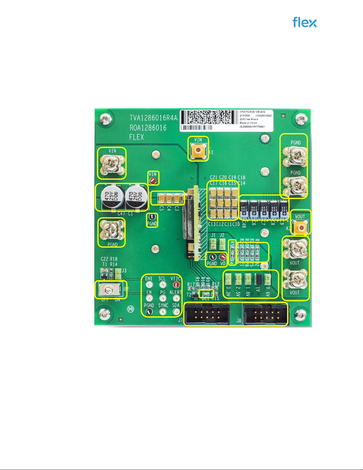
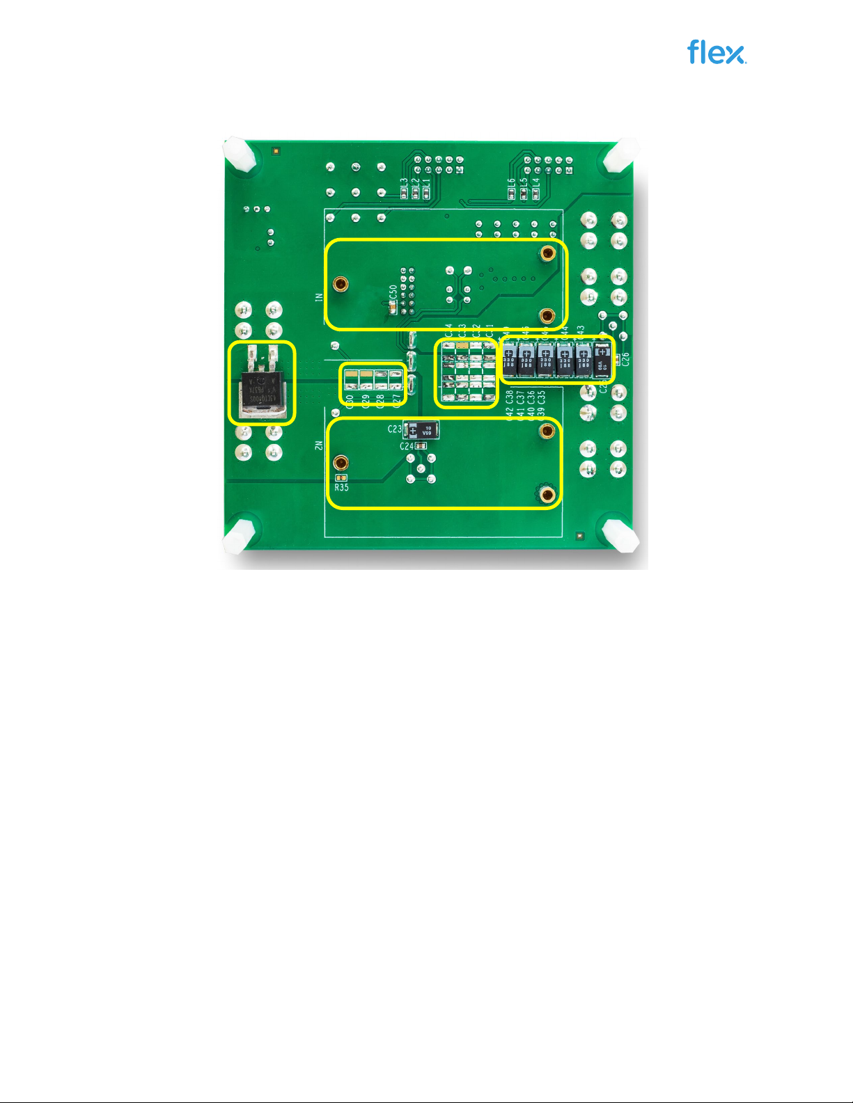
2Reference Board ROA 128 6016.......................................................... 5
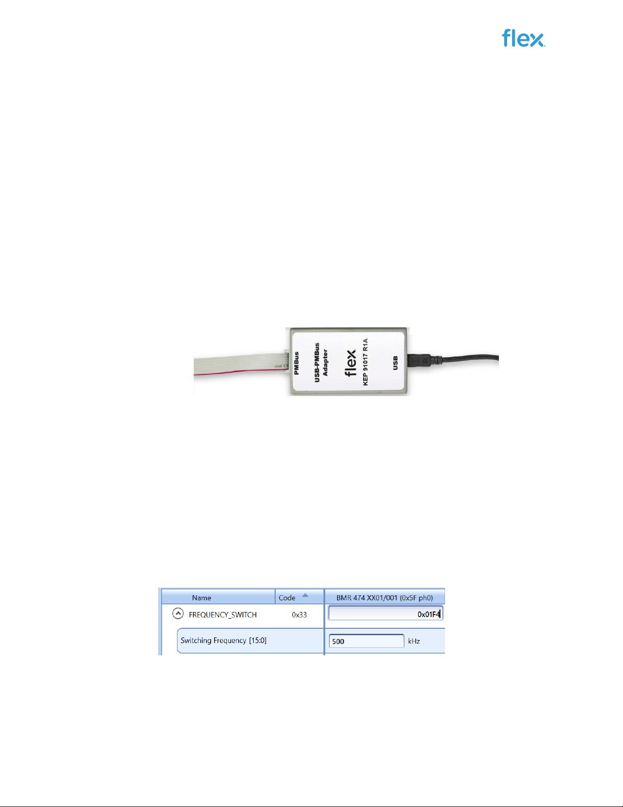
3USB-PMBus adapter ............................................................................ 7
3.1 Connection of Flex KEP 910 17 USB-PMBus adapter ........................... 7
4Power-up and Power-down Instructions ............................................ 7
4.1 Power-up instruction .............................................................................. 7
4.2 Power-down instruction.......................................................................... 8
5Address and VSET Resistor................................................................ 9
5.1 Adjustment of address resistor............................................................... 9
5.2 Adjustment of VSET resistors ................................................................ 9
6Test points............................................................................................ 9
7Additional Input/output Capacitance................................................ 10
8Electronic loads ................................................................................. 10
9Schematic........................................................................................... 11
10 Bill of Materials .................................................................................. 11
11 Layout description............................................................................. 12
11.1 PCB stack-up summary ....................................................................... 12
11.2 Input capacitance................................................................................. 14
11.3 Output capacitance .............................................................................. 14
12 Layout top view.................................................................................. 15