Semtech LoRa Edge Tracker Reference Design Evaluation... User manual

LoRa EdgeTM Tracker Reference Design
Evaluation User Guide
(“User Guide”)
July 2020

Table of Contents
Welcome! ........................................................................................................................................................... 4
What is in the Kit? .............................................................................................................................................. 4
System Overview ............................................................................................................................................... 5
Setting up the Kit Hardware............................................................................................................................... 6
Gateway Connections .................................................................................................................................... 6
About the Gateway ........................................................................................................................................ 7
Gateway Setup ............................................................................................................................................... 8
Gateway SIM and Data Connectivity ........................................................................................................... 12
Getting the Kit Online ...................................................................................................................................... 13
Creating the LoRa Cloud™ Portal Account ................................................................................................... 13
Claiming a device ..................................................................................................................................... 13
On boarding - Network Server Specific ........................................................................................................ 14
Selecting the Actility Network Server on the LoRa Cloud™ Device Join Server ........................................... 16
Creating the LoRa Cloud™ Device & Application Service (DAS) ................................................................... 16
Adding Devices ......................................................................................................................................... 17
The LoRa Cloud™ Geolocation ..................................................................................................................... 17
Types of Service ....................................................................................................................................... 17
Subscription Level and Tokens ................................................................................................................. 17
Getting Localization Results ..................................................................................................................... 18
Getting Almanac Data for GNSS Aiding .................................................................................................... 18
Creating your LoRa Cloud™ Geolocation Application Token ....................................................................... 18
Setup and Operation of the LR1110 Trackers .............................................................................................. 19
Download and Install Bluetooth Phone Application ................................................................................ 19
Putting Batteries in the LR1110 Tracker .................................................................................................. 19
Using the IOS/Android Bluetooth Application ......................................................................................... 20
Pairing LR1110 Tracker with Bluetooth ................................................................................................... 21
Setting up the Application to Retrieve Aiding .......................................................................................... 23
Application Features and Functions......................................................................................................... 25
Add Devices and Map Location .................................................................................................................... 29
Using the Web Dashboard ........................................................................................................................... 29
Device Tracking View ............................................................................................................................... 30
Device Settings View ................................................................................................................................ 30
Problems/Concerns .......................................................................................................................................... 31
Important Information: Warranty Disclaimer .................................................................................................. 32
Product & Safety Instructions ...................................................................................................................... 32
Warnings ...................................................................................................................................................... 32
Notices ......................................................................................................................................................... 33
Federal Communication Commission Interference Statement ................................................................... 33
Industry Canada statement ......................................................................................................................... 34

LoRa EdgeTM Tracker Reference Design
Evaluation Kit Welcome
Welcome!
The LoRa EdgeTM Tracker Reference Design Evaluation Kit (“Kit”) is a portable reference Kit designed to
introduce the LR1110 tracking capabilities with LoRa Cloud Services integrated with premium and showcase
LoRaWAN network coverage around a building or site and to accelerate solution development for a wide
range of stakeholders. The self-contained nature of this reference Kit makes it easy to set up, take down,
and move a network in a matter of minutes.
Users can determine a gateway’s range of coverage by moving the location of the sensors to different
places around a building. Furthermore, solution developers can focus on providing customer value through
data collection and analysis by using off-the-shelf hardware available from external suppliers.
The GPS location data of each tracker is displayed on a dashboard that users can access through a web
browser. The dashboard shows the type of displays that can be created with the data collected (See Figure
15 and Figure 16). The URL for the dashboard, and how to locate the login credentials for your Kit, are
explained in the Getting Started section of this guide.
Note: This Kit does not allow direct access to the underlying data or the ability to change the LoRaWAN
network server (LNS) to which the gateways are connected. If those features are desired requirements,
please contact Support at [email protected]o.
What is in the Kit?
The Kit contains the following items:
2 LR1110-based Tracking Devices
o Tracker on/off magnets (2) (not pictured)
o Toolset for battery door removal (not pictured)
o Extra batteries (not pictured)
1 LoRaWAN gateway with Ethernet backhaul
o Power brick with cable
o LoRa antenna with adapter (1)
o Ethernet cable (1)

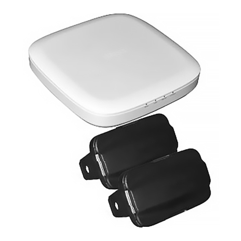
Figure 1: LR1110-based Tracking Device
Figure 2: LoRaWAN gateway with 3G/4G LTE (Cellular) backhaul
System Overview
The LoRa EdgeTM Tracker Reference Design Evaluation kit demonstrates and highlights the various aspects
of a LoRaWAN asset tracking system. The elements used in this system are highlighted in the following
diagram.
ANT2
ANT1
ANT3

The data flow proceeds from the LR1110 Tracking devices through the provided gateway in the kit to the
Actility LoRaWAN network server. This server manages the LoRaWAN network Join process through the
LoRa Cloud™ Device Join Server and once the LR1110 devices have joined the network, the Actility
LoRaWAN server is the conduit for data to and from the application service hosted by Tago.io. The Tago.io
service provides the interface to the position computation engine hosted on the LoRa Cloud™ Device &
Application and Geolocation Services and then provides tracking data for the devices available through a
web browser. Each part of this system is independently scalable to any size application as might be
deployed. This demonstration is the end-to-end deployment example of the latest LoRa® tracking solutions.
Not pictured is the Mobile Device Command and Control application that can run on IOS or Android devices
that can talk directly to the LR1110 Trackers to initialize and prepare them for operation.
Setting up the Kit Hardware
Gateway Connections
The gateway body has multiple connectors for antennas and cables. The following table describes those
connections.
ANT 1
GPS antenna connector (N
-
type female)
Ethernet
P
ower
-
o
ver
-
E
thernet
connector
ANT 2
3G/4G antenna connector
(N
-
type female)
ANT 3
915/868 MHz
LoRa
antenna connector (N
-
type female)
3G/4G
Access port for 3G/4G SIM card
ANT 4
915/868 MHz antenna connector (not
connected
)

Figure 3: Gateway connections
About the Gateway
The ODU gateway is an 8-channel LoRaWAN-compliant gateway with external antennas. This gateway has
the following features:
Support for LoRa Basics™ Station
Gateway ping
Support for LoRaWAN 1.0.2 or higher
8+ LoRa channels
External antenna (for greater range)
Indoor/Outdoor form factor
Modular support for 3G/4G
Optional features (Not supported out-of-the-box)
o GNSS/precise timing support (for GNSS aiding messages/synchronized downlinks)
o Outdoor mounting support
o IP67 rating for outdoor mounting

Gateway Setup
To set up the gateway, follow the steps below.
Note: Do not connect power until all antenna connections are complete.
Step 1: Connect the adapter to the LoRa antenna
Figure 4: Adapter connection
Step 2: Connect the LoRa antenna to the gateway (ANT3)
Figure 5: Connecting the LoRa antenna to the gateway

Step 3: Connect the Ethernet cable to the gateway
Figure 6: Connecting the Ethernet cable to the gateway
Step 4: Connect the Ethernet cable to the power brick.
NOTE: Do not connect Ethernet plug to the jack on the right
Figure 7: Ethernet cable connected to the power brick

Step 5: Connect the Cellular antenna (ANT2)
Figure 8: Connecting the Cellular antenna to the gateway
Step 6: (Optional) Connect the GPS cable to the GPS Antenna
Figure 9: Connecting the GPS cable to the GPS antenna

Step 7: (Optional) Connect the GPS cable to the gateway (ANT1)
Figure 10: Connecting the GPS cable to the gateway
Step 8: Connect the power brick to a power source.
Figure 11: Connecting mains cable to power brick

Step 9: Verify and test. Check the LED on the power brick.
The LED will be green when power is supplied to the gateway.
Figure 12: Green LED on Power Brick Means Gateway is Powered
Gateway SIM and Data Connectivity
The gateway is provided with a SIM card for cellular backhaul. This includes 1GB of free data service, which
should be adequate for about one year of operation. If you need more data, you will need to sign up for a
cellular service plan and provide a replacement SIM card. The SIM card can be accessed through the clear,
sealed access port (the 3G/4G port in Figure 7) on the side of the gateway with the LoRa antenna.

Getting the Kit Online
There are a few steps involved in getting your LR1110 Trackers online for the first time. The process of
setting up the devices will be illustrative of the overall setup and system configuration. By following the
steps outlined below, you should be up-and-running in less than 30 minutes.
Creating the LoRa Cloud™ Portal Account
Before a LR1110 Tracker device can be claimed however, you first must have an account on the LoRa
Cloud™. To setup your account, navigate in a browser to https://www.loracloud.com. On that page you will
see a “Get Started” button.
You will be presented with an option to create an account. Use your email address and create a password.
You will be sent a confirmation email for the account. Click on the confirmation link in the email and you
will be taken to the login page. After logging into your new account, you will need to accept the Terms &
Conditions of Usage and your account activation will be complete.
Claiming a device
To claim a device, first you start off on the LoRa Cloud™ Device Join portal at
https://www.loracloud.com/portal/join_service. From there, select the “Devices” link on the left pane and
you will be presented with a Join Server page. Under the “Devices” header, you will be presented with two
options to “Claim Individual Device” or “Bulk Upload (CSV)”. As was previously discussed, you can get the
required information for each LR1110 Tracker device directly from the modem API. If you select the “Claim
Individual Device” you will be presented with a form that looks like this:

Enter the EUI and the PIN (Claim) retrieved from the modem and press “Claim Device”. If the EUI and PIN
are matched in the LoRa Cloud™ Device Claim system, it will be added to your available devices. You could
have also used the “Bulk Upload(CSV)” option to provide the LoRa Cloud™ Device Join service with the
information that you entered on the form; however, it would need to be in a file with the provided format
on that page.
The last method for claiming a device is using the Application Owner API of the LoRa Cloud™ Device Join
Server. This provides a secure REST interface to upload the claim information (specifically the
“claim_devices” endpoint). This interface is documented at:
https://www.loracloud.com/documentation/join_service?url=appo_api.html
On boarding - Network Server Specific
For the LoRa Cloud™ Device Join Server to handle the Join of the device, it needs to be associated with the
Network Server that will route the traffic to and from the device. Since you may want to setup one set of
devices for one LoRaWAN network server. The diagram below shows two configuration setup examples. In
the top example, a block of devices will be configured for LoRaWAN Network Server 1 (LNS_1) the Join
Requests for devices received from that LNS for a claimed device will use the application configuration logic
for appo-::a in the system. This is set on the LoRa Cloud™ Device Join Network Servers configuration page
or through the Application Owner API documented here
(https://www.loracloud.com/documentation/join_service?url=appo_api.html).
The second configuration setup example allows for devices to come through one of two different LNS
endpoints for the same application definition.

The purpose of mapping the Registered Network Server to a specific Application Owner is so that specific
parameters can be setup for handling data when operating with that LNS. There are three common settings
for each Application definition: name, wrapkey and nslist. The name is an arbitrary string to represent the
application. The wrapkey is a specific token used for encrypting the AppSKey from the LoRaWAN session
(the unencrypted AppSKey is used for encrypting the LoRaWAN payload data between the device and
Application Server in LoRaWAN). The wrapkey can be null indicating that the AppSKey will be passed from
the LoRaWAN Network Server to the Application Server unencrypted. For more information on working
with the AppSKey, please see the documentation at
https://www.loracloud.com/documentation/join_service?url=appskey.html. The nslist is a list of LoRaWAN
network servers that will be associated with this Application Owner configuration.
Once the Network Servers are configured for a particular Application Owner on the LoRa Cloud™ Device
Server, then the device Join process can be performed. The LoRaWAN Network server that sees the Join
Request from the claimed device will forward this onto the LoRa Cloud™ Device Join Service. It will securely
access the root keys for the device, processing this on a HSM1 which derives the session keys and returns
them along with the Join Response to the Network Server. If a wrapkey is defined for the Application
associated with the Network Server, the AppSKey is returned encrypted otherwise, it will be in plaintext.
The LoRaWAN Network Server will send the Join Response to the device. Once a data message is sent after
the Join Response to the LoRaWAN Network Server, the joining will be complete and the device will be
configured for operation on that LNS.
1 HSM stands for Hardware Security Module. A HSM is a dedicated piece of computer equipment with a defined API
that allows for the processing and distribution of secure keys and tokens in a completely self-contained device. The
workings of the HSM are beyond the scope of this document.

Selecting the Actility Network Server on the LoRa Cloud™ Device Join Server
Once the owner has been established, you must select the Network Server on the LoRa Cloud™ Device Join
Server. To do this, go to the “NETWORK SERVERS” link on the left and on the Network Servers page select
the Actility ThingsPark Wireless DEV1 and hit “ADD”. Currently the “Owner Context” for these devices is not
defined.
Creating the LoRa Cloud™ Device & Application Service (DAS)
In order to utilize the DAS for your LR1110 Trackers, you must create an Application Owner and then create
a token that will be added to the transmission of the data to the DAS.

To create an owner that can use the DAS, first login to your LoRa Cloud™ account
(https://www.loracloud.com) and select the “LoRa Cloud™ Device and Application Services”. There is a
“Manage Owners” page accessible from the main DAS page. On the “Manage Owners” page you will create
an owner or owners and then set the currently active owner. The active owner is where you will define
tokens with the properties you need. A token can have at least one, up to all of the following permissions:
Add/Delete Devices
Deliver Uplinks
Issue Device Requests
List/Read Device State
Add/Delete Tokens
List Tokens
When you add a token, you select its permissions. Once set, the permissions of the token cannot be
changed but a token can be renamed or deleted at any time. You will use a defined token will be to access
the various commands available in the DAS API to add new devices and list current devices. You can even
list and add new tokens if the token you use has sufficient permission. One of the most important uses of
the token will be to transmit and receive data to and from the DAS. This token will be needed for the
provisioning on the Tago.io account interface.
Adding Devices
Devices are managed either through the DAS API or directly from the LoRa Cloud™ Device & Application
Services (DAS) web portal. The “Manage Devices” link is used to add devices for a specific owner
application. The only necessary information to add a device to the list of managed devices is the EUI; you
can add the EUIs of the two LR1110 Trackers at the same time or one at a time.
The LoRa Cloud™ Geolocation
The LoRa Basics™ Modem-E has built-in features for geolocation. This information can be sent to the LoRa
Cloud™ Geolocation API for estimating the location the device. When gateways receive a data packet
transmitted by LoRa Basics™ Modem-E devices, they also generate metadata such as received signal-
strength, signal-to-noise ratio and time of arrival. When this metadata from the gateways is assembled into
a suitable query, and transmitted via the LoRa Cloud™ Geolocation API, the service is able to calculate the
location of the device.
Types of Service
There are three localization technologies available: LoRa, Wi-Fi and GNSS. The LoRa method uses signal
strength, signal timing and other meta data from the device signals to calculate a location. Similarly, the Wi-
Fi method uses signal strength of Wi-Fi Access Points within range of the device to estimate the location of
the device. Finally, the LoRa Basics™ Modem-E has the ability to measure timing information from multiple
GNSS satellite sources to estimate the position based on those signals.
Subscription Level and Tokens
There are different levels of subscription for the LoRa Cloud™ Geolocation service depending on the
monthly traffic levels that will be utilized by a given application. Each account will have two default tokens,
primary and secondary. The combined traffic associated with both tokens will be accumulated. The
accumulated totals will count towards the monthly total. For the introductory free tier, up to 1000

locations can be computed every month. Paid plan quotas range from the hundreds of thousands to many
millions. See the link https://www.loracloud.com/portal/geolocation/subscription_management for further
information on pricing plans.
Getting Localization Results
To utilize the LoRa Cloud™ Geolocation API, the LR1110 Tracker will provide scan information for LoRa®
signals, Wi-Fi scan or GNSS measurements. The LoRa® signals and Wi-Fi scan will be passed through the
provided gateway, to the LNS and then onto the cloud systems which will compute location and display
them on a map (discussed later).
Getting Almanac Data for GNSS Aiding
GNSS operates by utilizing ranging measurements from a satellite to a receiver (in this case the LR1110
Tracker device). The acquisition of the signals can be improved by providing information about the GNSS
satellites and the currently local conditions. The LoRa Cloud™ Device & Application Service (DAS) allows for
timing information to be provided to the LR1110 Tracker through the clock synchronization protocol.
Additionally, there are two supported levels of almanac aiding to provide GNSS satellite predictions. The
two almanacs are the “efficient” (i.e., compact) almanac as well as the full almanac. The efficient approach
is optimized for lower communication bandwidth. Over time, the true satellite positions diverge from the
fixed Almanac parameters, which requires them to be updated. DAS is designed to allow for those updates
on a regular basis.
Creating your LoRa Cloud™ Geolocation Application Token
The Geolocation Application Token is provided at:
https://www.loracloud.com/portal/geolocation/token_management. This will be needed for the
provisioning on the Tago.io account interface.

Setup and Operation of the LR1110 Trackers
The LR1110 Trackers are shipped with batteries outside of the unit so that they will not transmit while in
transport. This section will provide the instructions for the setup of the device, pairing it with its
initialization phone application and connecting to the services it supports.
Download and Install Bluetooth Phone Application
The first step in setting up your devices is to download, install and run the Bluetooth Phone application
that enables the initial configuration of the LR1110 Tracker device. The LR1110 Tracker application is
available on Google Play for Android under the name “LR1110” or via the APK provided on a thumb
drive. For IOS users, search the App Store for “LR1110” and download and install the application.
Once the application is downloaded to your phone, run the application.
Putting Batteries in the LR1110 Tracker
The process for putting the supplied batteries in the Tracker as follows; first remove the four screws from
back cover from the device using a T8 Torx head screwdriver:
Next, insert the batteries in the desired orientation:

Make sure that the batteries are oriented in the correct direction lining up the “+” and “-“ symbols on the
device:
Place the bottom plate back on the device and secure all four screws completely.
Using the IOS/Android Bluetooth Application
The application will present a screen like the following on startup:
Place the provided magnet with the notch-side down against the oval hole on the device:
Table of contents
Other Semtech Motherboard manuals

Semtech
Semtech SX1211SK915 User manual

Semtech
Semtech GS3440 User manual

Semtech
Semtech SC120 User manual

Semtech
Semtech LoRa Edge LR1110 User manual

Semtech
Semtech SX8650 User manual

Semtech
Semtech SX8651EVK User manual

Semtech
Semtech SX8634 User manual

Semtech
Semtech EB-GS3471-00 User manual

Semtech
Semtech SC202A EVB User manual

Semtech
Semtech TSWITX-12V-EVM User manual