Flexco MHCP Technical Document

MHCP Primary Cleaner
Installation, Operation
and Maintenance Manual
www.flexco.com
www.flexco.com

MHCP Primary Cleaner
Purchase Date:______________________________________________________________
Purchased From: ____________________________________________________________
Installation Date: ____________________________________________________________
This information will be helpful for any future inquiries or questions about belt cleaner
replacement parts, specifications or troubleshooting.

3
Table of Contents
Section 1 – Important Information ...........................................................................................................4
1.1 General Introduction ..................................................................................................................................4
1.2 User Benets ................................................................................................................................................4
1.3 Service Option .............................................................................................................................................4
Section 2 – Safety Considerations and Precautions ..................................................................................5
2.1 Stationary Conveyors..................................................................................................................................5
2.2 Operating Conveyors ..................................................................................................................................5
Section 3 – Pre-Installation Checks and Options......................................................................................6
3.1 Checklist .......................................................................................................................................................6
3.2 Cleaner Location Adjustments ..................................................................................................................7
Section 4 – Installation Instructions..........................................................................................................8
Section 5 – Pre-Operation Checklist and Testing....................................................................................12
5.1 Pre-Op Checklist .......................................................................................................................................12
5.2 Test Run the Conveyor .............................................................................................................................12
Section 6 – Maintenance ..........................................................................................................................13
6.1 New Installation Inspection ...........................................................................................................................13
6.2 Routine Visual Inspection........................................................................................................................13
6.3 Routine Physical Inspection.....................................................................................................................13
6.4 Blade Replacement Instructions..............................................................................................................14
6.5 Maintenance Log .......................................................................................................................................16
6.6 Cleaner Maintenance Checklist...............................................................................................................17
Section 7 – Troubleshooting ....................................................................................................................18
Section 8 – Specs and CAD Drawings......................................................................................................19
8.1 Specications and Guidelines.........................................................................................................................19
8.2 CAD Drawings...........................................................................................................................................20
Section 9 – Replacement Parts .................................................................................................................22
9.1 Replacement Parts List..............................................................................................................................22
9.2 Optional Assemblies, Tensioners & Kits.................................................................................................23
Section 10 – Other Flexco Conveyor Products........................................................................................27

4MHCP Primary Cleaner
1.1 General Introduction
Section 1 – Important Information
We at Flexco are very pleased that you have selected a MHCP Primary Cleaner for your conveyor system.
is manual will help you to understand the operation of this product and assist you in making it work up to
its maximum eciency over its lifetime of service.
It is essential for safe and ecient operation that the information and guidelines presented be properly
understood and implemented. is manual will provide safety precautions, installation instructions,
maintenance procedures and troubleshooting tips.
If, however, you have any questions or problems that are not covered, please visit our web site or contact our
Customer Service Department:
Customer Service: +27-11-608-4180
Visit www.exco.com for other Flexco locations and products.
Please read this manual thoroughly and pass it on to any others who will be directly responsible for
installation, operation and maintenance of this cleaner. While we have tried to make the installation and
service tasks as easy and simple as possible, it does however require correct installation and regular
inspections and adjustments to maintain top working condition.
1.2 User Benets
Correct installation and regular maintenance will provide the following benets for your operation:
• Reduced conveyor downtime
• Reduced man-hour labor
• Lower maintenance budget costs
• Increased service life for the belt cleaner and other conveyor components
1.3 Service Option
e MHCP Primary Cleaner is designed to be easily installed and serviced by your on-site personnel.
However, if you would prefer complete turn-key factory service, please contact your local Flexco Field
Representative.

5
Section 2 – Safety Considerations and Precautions
Before installing and operating the MHCP Primary Cleaner, it is important to review and understand the following
safety information.
There are set-up, maintenance and operational activities involving both stationary and operating conveyors. Each
case has a safety protocol.
2.1 Stationary Conveyors
The following activities are performed on stationary conveyors:
• Installation • Blade replacement • Repairs
• Tension adjustments • Cleaning
DANGER
DANGER
WARNING
WARNING
WARNING
!
!
!
!
!
It is imperative that Lockout/Tagout (LOTO)
regulations, be followed before undertaking the
preceding activities. Failure to use LOTO exposes
workers to uncontrolled behavior of the belt cleaner
caused by movement of the conveyor belt. Severe injury
or death can result.
Before working:
• Lockout/Tagout the conveyor power source
• Disengage any takeups
• Clear the conveyor belt or clamp securely in place
Use Personal Protective Equipment (PPE):
• Safety eyewear
• Hardhats
• Safety footwear
Close quarters, springs and heavy components create
a worksite that compromises a worker’s eyes, feet
andskull.
PPE must be worn to control the foreseeable hazards
associated with conveyor belt cleaners. Serious injuries
can be avoided.
2.2 Operating Conveyors
There are two routine tasks that must be performed while the conveyor is running:
• Inspection of the cleaning performance
• Dynamic troubleshooting
Every belt cleaner is an in-running nip hazard. Never
touch or prod an operating cleaner. Cleaner hazards
cause instantaneous amputation and entrapment.
Never adjust anything on an operating cleaner.
Unforseeable belt projections and tears can catch on
cleaners and cause violent movements of the cleaner
structure. Flailing hardware can cause serious injury
ordeath.
Belt cleaners can become projectile hazards. Stay as far
from the cleaner as practical and use safety eyewear and
headgear. Missiles can inflict serious injury.

6MHCP Primary Cleaner
3.1 Checklist
Section 3 – Pre-Installation Checks and Options
• Check that the cleaner size is correct for the beltline width
• Check the belt cleaner carton and make sure all the parts are included
• Review the “Tools Needed” list on the top of the installation instructions
• Check the conveyor site:
- Will the cleaner be installed on a chute
- Are there obstructions that may require cleaner location adjustments
(see 3.2 – Cleaner Location Adjustments)
- Is the install on an open head pulley requiring mounting structure
(see 3.3 – Optional Installation Accessories)
7
3.2 Cleaner Location Adjustments
Section 3 – Pre-Installation Checks and Options
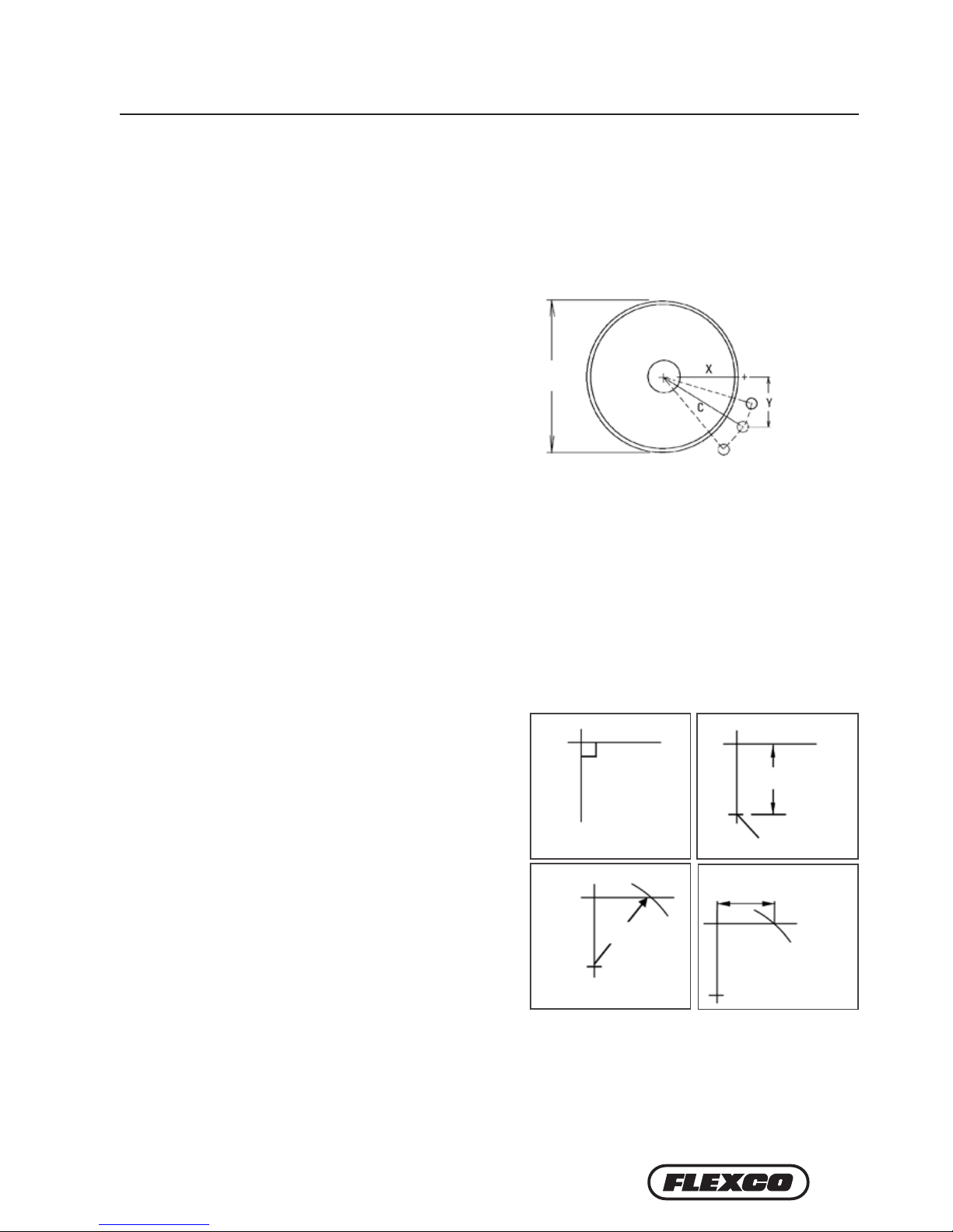
In certain applications it is necessary to modify the location of the primary cleaner pole due to permanent
obstacles that obstruct the desired location. Relocating the pole location can be done easily and does not hinder the
performance of the cleaner as long as the “C” dimension is maintained.
NOTE: In the following example we will be lowering the pole location in the “Y” direction, but the same method
could also be applied in the “X” direction.
Conveyor situation:
Pulley Diameter: 900mm
X = 450mm
Y = 359mm
C = 575mm
1. Determine the given location dimensions and define the change needed. After laying out the given X & Y
dimensions, determine the distance of the modification required for adequate clearance of the pole and tensioning
system. (In the example we decide to lower the pole 50mm to clear the support structure).
2. Write down known dimensions. We can now determine two of the three required dimension which will allow us
to find the third. We know we cannot alter the “C” dimension, so this will remain the same. Also we are required to
lower the unit in the “Y” dimension 50mm, so we add 50mm to the given “Y” dimension.
X = ? mm
Y =359+50=409mm
C = 575mm
3. Determine final dimension. On a flat vertical surface,
using a level, draw one horizontal line and one vertical
line creating a right triangle (Fig 3a). Measure down from
the intersection the determined “Y” dimension and mark
(Fig 3b). With the tape measure starting at the modified
“Y” mark, swing the tape across the “X” line and mark at
the “C” dimension where it crosses the “X” line (Fig 3c).
Measure from the intersection to the “C” intersection and
this will be your new “X” dimension (Fig. 3d).
X = 403mm
Y = 409mm
C = 575mm
900 mm
Fig. 3a
Fig. 3c
Fig. 3b
Fig. 3d
Y 409 mm
mark
This distance is the new
“X” dimension
403 mm
C 575 mm
8MHCP Primary Cleaner
Section 4 – Installation Instructions
Physically lock out and tag the conveyor at the power source
before you begin cleaner installation.
1. Find the X, Y & C specifications. Measure the pulley diameter
(including the belt and the lagging) (Fig. 1).
Pulley Diameter _____mm; X=_____mm; Y=_____mm; C=_____mm.
(Adjustments can be made to the X & Y coordinates to move away
from obstacles as long as the C dimension remains constant.)
CAUTION: Components may be heavy. Use safety-approved lifting procedures.
X & Y Chart for Pole Location
Pulley Diameter
(including belt
and lagging) X Y C
500 254 365 445
525 267 365 451
550 279 365 460
575 292 365 467
600 305 365 476
625 318 365 483
650 330 365 492
675 343 365 502
700 356 365 511
725 368 365 518
750 381 365 527
775 394 365 537
800 406 365 546
825 419 365 556
850 432 365 565
875 445 365 575
900 457 365 584
925 470 365 594
950 483 365 606
975 495 365 616
1000 508 365 625
1025 521 365 635
1050 533 365 648
1075 546 365 657
1100 565 365 673
1125 581 365 686
1150 597 365 699
1175 610 365 711
1200 625 365 724
Blades per Cleaner Size
mm 600 750 900 1050 1200 1350 1500 1800
Blades Required 3 4 5 6 7 8 9 11
4.1 MHCP Primary Cleaner
Tools Needed:
• Tape Measure
• Wrenches or Crescent Wrenches: (2)19mm,
(2) 38mm, (1) 24mm, and (1) 16mm
• C-clamps for AWT only
Fig. 1
X
C
Y
Pole Location Specs
Pulley Diameter
(incl. belt and
lagging)
AWT Air/Water Tensioner
PST Spring Tensioner
Supershear Blades
Blade Cartridge
Centre Pole
Extender Pole
MHCP Parts List
Chute Wall
Recommended spacing from back chute wall
Maximum
lump size
+ 200mm (8")
9
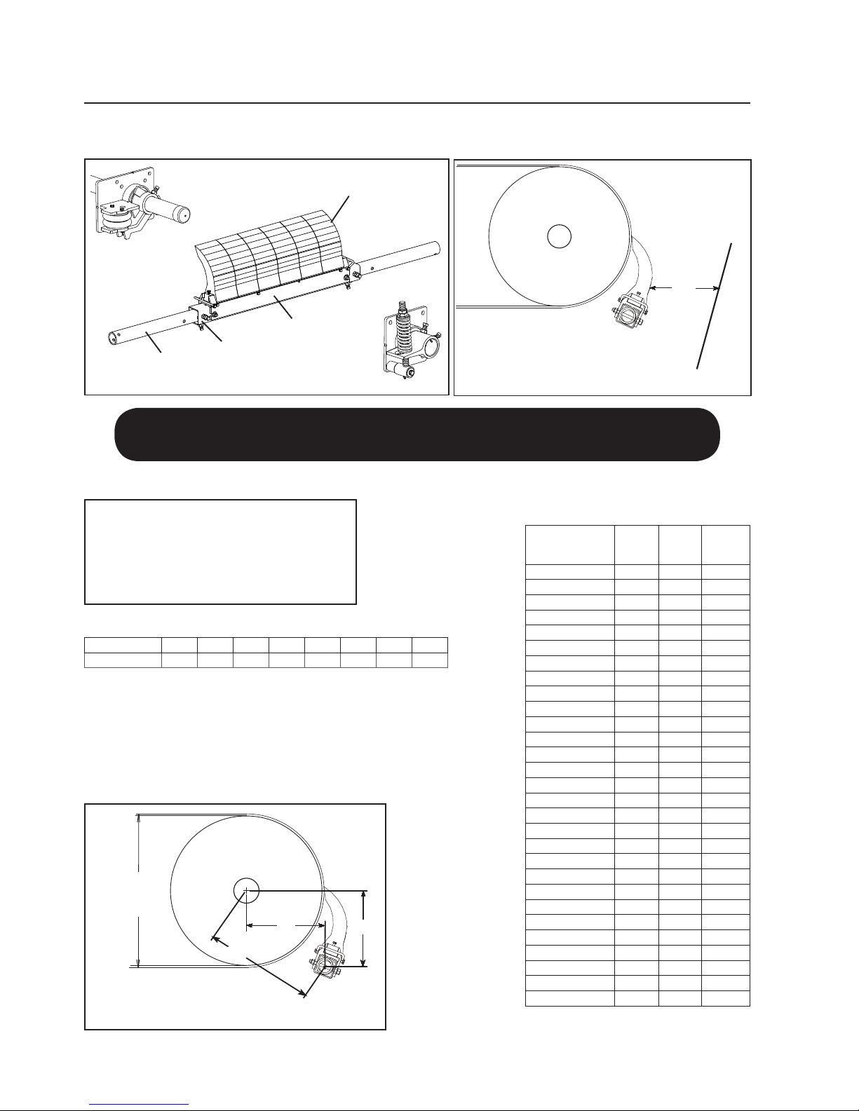
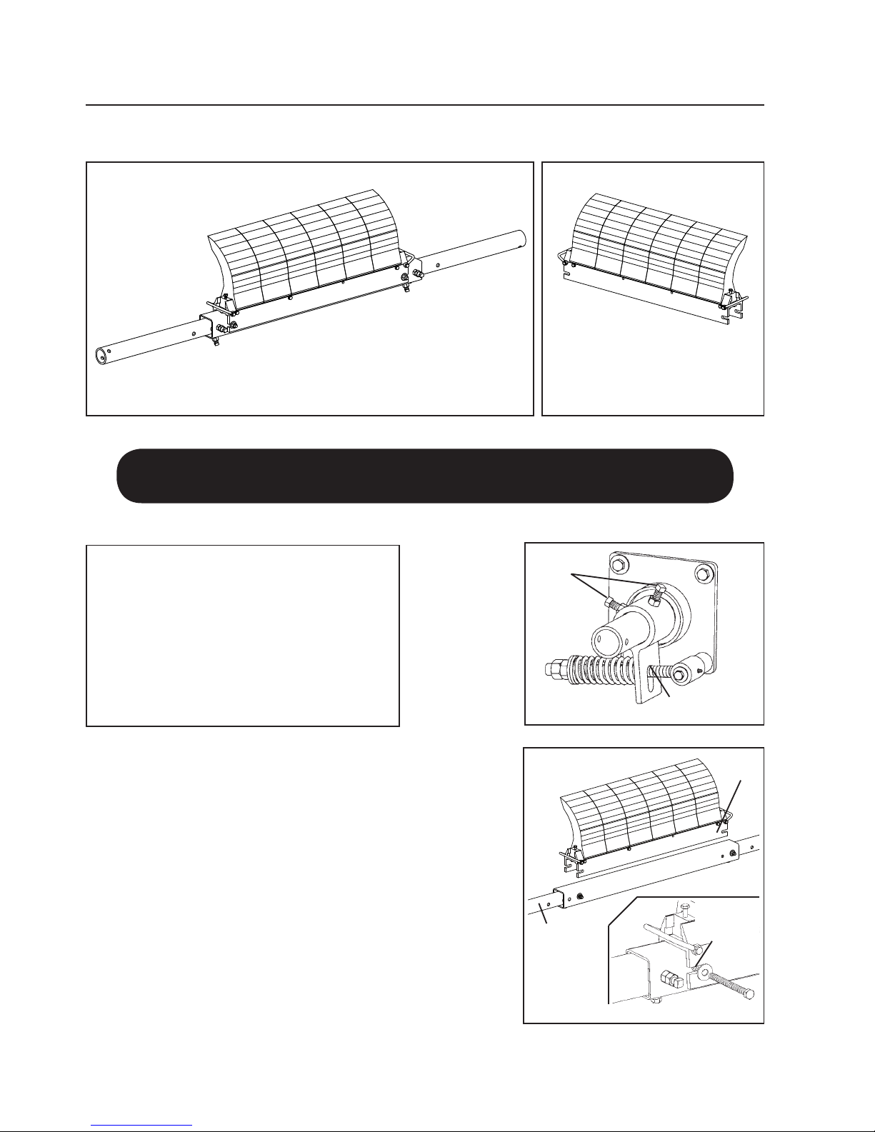
5. Install the mounting bases.
Bolt the mounting bases to the
chute with the bolts provided
(Fig. 5).
6. Install the blade cartridge.
Place the blade cartridge onto
the centre pole. Adjust the
extender poles until the holes
align with the holes in
the centre pole and lock the cartridge into place with the two bolts,
washers and nuts (Fig. 6). NOTE: Be sure at least 150mm of the extender
pole extends out of the mounting base on each side for tensioner
installation. Adjust the extender poles in the centre pole if more or less
length is needed.
Section 4 – Installation Instructions
2. Lay out the dimensions on the chute wall. Measure out the X dimension
horizontally from the centre of the pulley shaft and mark. (NOTE: It may be
easier to put a level on top of the pulley shaft, draw a horizontal line and then
measure down half the diameter of the shaft and make a line from the front of
the shaft. Now subtract half the pulley shaft diameter from the X coordinate
and measure on the line and make a mark.) Then measure down vertically the
Y dimension and mark. This is the correct position for the centre of the cleaner
pole (Fig. 2). Lay out and mark the same dimensions on the other side.
3. Mark and cut the mounting base holes. Using the
mounting base template provided in the instruction packet,
position the large pole hole of the template on the chute with
the hole notches aligned with the layout lines. Trace the pole
hole and mounting holes (Fig. 3). Each base can be mounted
in any position 360° around the pole as long as the pole’s
centre point does not change. Cut the holes on both sides of
the chute.
4. Assemble the extender poles to the centre pole. Insert the
extender poles through the chute holes and into the centre
pole and make sure the locating bolt holes align with the
centre pole holes (holes are offset to the lower half). Position
the centre pole with the welded nuts and locking bolts on
one side facing down and on the adjoining side facing away
from the head pulley (Fig. 4). Leave the locking bolts loose.
4. 1 MHCP Primary Cleaner (cont.)
mark
Y
X
mark
Center large template hole notches on pole center mark,
rotate to desired angle and trace holes
Template for
PST mounting baseTemplate for
AWT/NT mounting base
Blade
Cartridge
6" of pole end
must extend
outside the
mounting base
on each side
Align holes
and install
bolts, washers
and nuts
Extender
Pole
Mounting Plate
(Pst Shown)
Chute wall
(cut away)
Chute wall
(cut away)
Center Pole
Extender Pole
Must be facing
away from
head pulley
Locating bolt
holes
Locking
Bolts
Must align with
extender pole
holes
Must be
facing down
Fig. 2
mark
Y
X
mark
Center large template hole notches on pole center mark,
rotate to desired angle and trace holes
Template for
PST mounting baseTemplate for
AWT/NT mounting base
Blade
Cartridge
6" of pole end
must extend
outside the
mounting base
on each side
Align holes
and install
bolts, washers
and nuts
Extender
Pole
Mounting Plate
(Pst Shown)
Chute wall
(cut away)
Chute wall
(cut away)
Center Pole
Extender Pole
Must be facing
away from
head pulley
Locating bolt
holes
Locking
Bolts
Must align with
extender pole
holes
Must be
facing down
Fig. 3
mark
Y
X
mark
Center large template hole notches on pole center mark,
rotate to desired angle and trace holes
Template for
PST mounting baseTemplate for
AWT/NT mounting base
Blade
Cartridge
6" of pole end
must extend
outside the
mounting base
on each side
Align holes
and install
bolts, washers
and nuts
Extender
Pole
Mounting Plate
(Pst Shown)
Chute wall
(cut away)
Chute wall
(cut away)
Center Pole
Extender Pole
Must be facing
away from
head pulley
Locating bolt
holes
Locking
Bolts
Must align with
extender pole
holes
Must be
facing down
Fig. 4
mark
Y
X
mark
Center large template hole notches on pole center mark,
rotate to desired angle and trace holes
Template for
PST mounting baseTemplate for
AWT/NT mounting base
Blade
Cartridge
6" of pole end
must extend
outside the
mounting base
on each side
Align holes
and install
bolts, washers
and nuts
Extender
Pole
Mounting Plate
(Pst Shown)
Chute wall
(cut away)
Chute wall
(cut away)
Center Pole
Extender Pole
Must be facing
away from
head pulley
Locating bolt
holes
Locking
Bolts
Must align with
extender pole
holes
Must be
facing down
Fig. 5
Fig. 6 Blade
Cartridge
150 mm of pole
end must extend
outside the
mounting base
on each side
Align holes
and install
bolts, washers
and nuts
10 MHCP Primary Cleaner
Section 4 – Installation Instructions
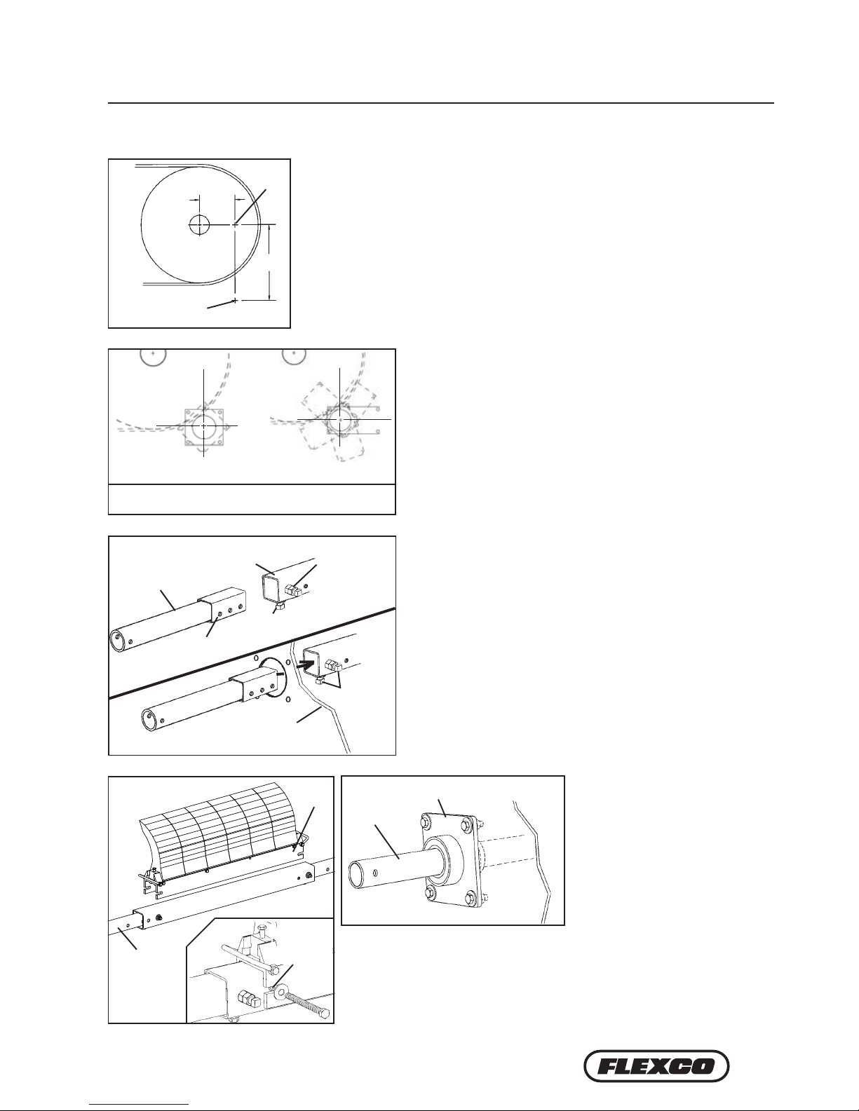
7. Centre the blades on the belt.
Slide the pole until the blades
are centreed or cover the belt’s
material path (Fig. 7). NOTE:
Standard blade coverage is
belt width minus 150mm. If
less blade coverage is required,
single blades can be removed
from the blade cartridge.
The blades do not have to be
centred in the cartridge. They
should be centred on the belt’s
material path.
8. Lock the extender poles in the centre pole. Tighten the two locking bolts and jam nuts on each end of the centre
pole (Fig. 8).
Install the tensioning system. For the PST Spring Tensioner go to step 9S. For the AWT Air/Water or PAT
Tensioner proceed to step 9A.
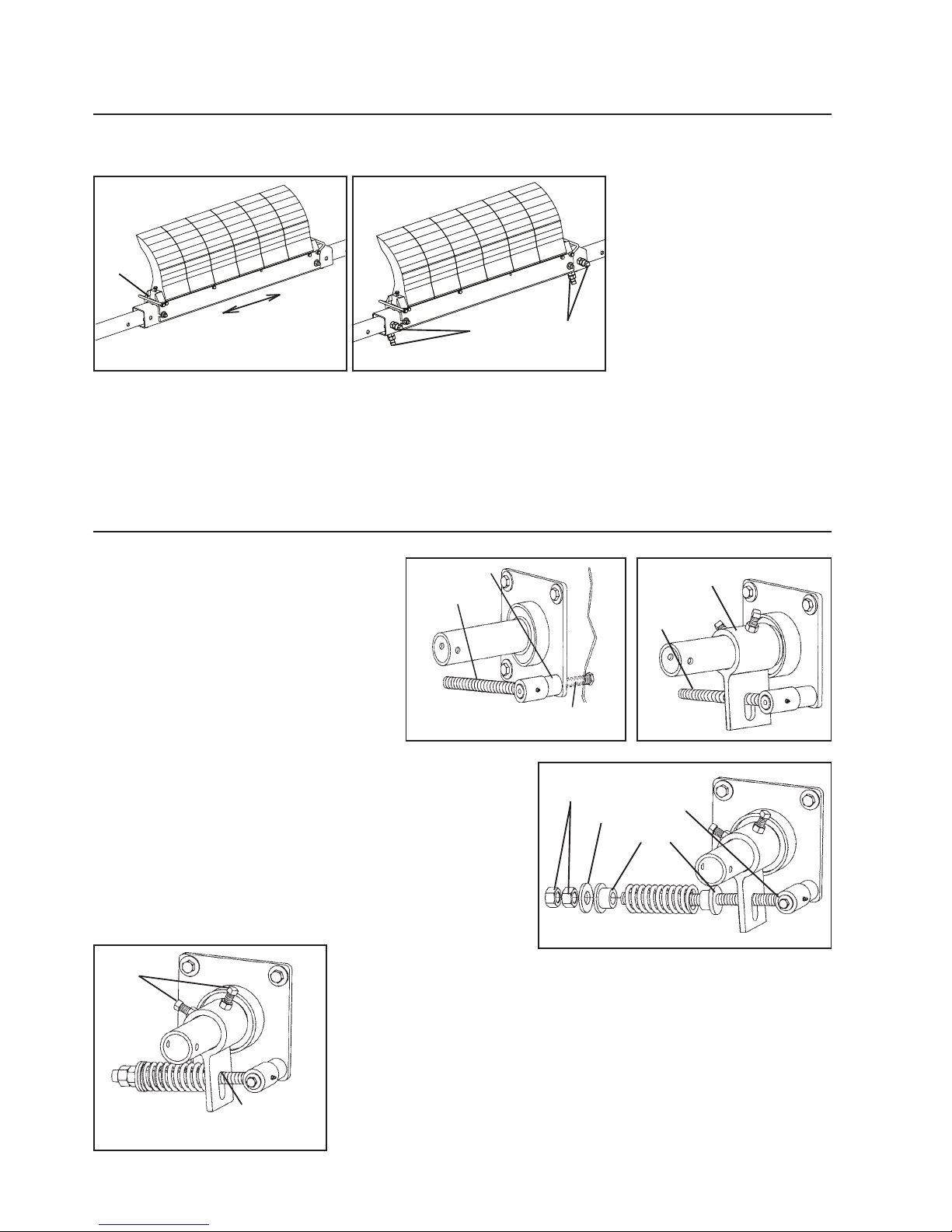
9S. Install the torque pivot rod. Remove the
adjusting nuts and springs from the rods.
The pivot rod base can be installed in any of
the four mounting plate holes. Determine
the rotation desired. Insert the pivot rod
mounting bolt through the chute wall and
the mounting plate and into the pivot rod
base and tighten (Fig. 9S).
10S. Slide the torque arm onto the pole end. Again ensuring the
correct pulling rotation, put the torque arm onto the pole end
and rotate it around until the torque pivot rod slides through
the slot (Fig. 10S).
11S. Reassemble the spring assembly. Slide the spring, washer and
bushings onto the pivot rod and turn the two adjusting nuts
so about 6mm of the rod is exposed above the nuts (Fig. 11S).
Complete steps 9S through 11S on the other side.
12S. Tension the blades to the belt. Rotate the blades until they contact the
belt. While holding the spring bushing flat on the torque arm, rotate the
torque arm until the pivot rod is against the end of the slot nearest the
pole. Tighten the locking bolts and jam nuts on the torque arm (Fig. 12S).
NOTE: The torque arm should be up against the mounting base.
Primary Cleaner Spring
Tensioner (PST)
4.1 MHCP Primary Cleaner (cont.)
Fig. 7 Fig. 8
Slide pole to center
blades or cover
belt’s material path
Remove
blade stop
to slide
blade(s)
off if
necessary
Tighten locking bolts and
jam nuts (both ends)
Slide pole to center
blades or cover
belt’s material path
Remove blade
stop to slide
blade(s) off if
necessary
Tighten locking bolts and
jam nuts (both ends)
Pivot Rod
Bushings
Adjusting
Nuts
Washer
Torque
Arm
Torque
Pivot Rod
Pivot Rod Base
Torque Pivot
Rod
Chute
Wall
(cut
away)
Pivot Rod
Mounting Bolt
Pivot rod against slot
end nearest the pole
Tighten
locking bolts
and
jam
nuts
Fig. 9S
Slide pole to center
blades or cover
belt’s material path
Remove blade
stop to slide
blade(s) off if
necessary
Tighten locking bolts and
jam nuts (both ends)
Pivot Rod
Bushings
Adjusting
Nuts
Washer
Torque
Arm
Torque
Pivot Rod
Pivot Rod Base
Torque Pivot
Rod
Chute
Wall
(cut
away)
Pivot Rod
Mounting Bolt
Pivot rod against slot
end nearest the pole
Tighten
locking bolts
and
jam
nuts
Fig. 10S
Slide pole to center
blades or cover
belt’s material path
Remove blade
stop to slide
blade(s) off if
necessary
Tighten locking bolts and
jam nuts (both ends)
Pivot Rod
Bushings
Adjusting
Nuts
Washer
Torque
Arm
Torque
Pivot Rod
Pivot Rod Base
Torque Pivot
Rod
Chute
Wall
(cut
away)
Pivot Rod
Mounting Bolt
Pivot rod against slot
end nearest the pole
Tighten
locking bolts
and
jam
nuts
Fig. 11S
Slide pole to center
blades or cover
belt’s material path
Remove blade
stop to slide
blade(s) off if
necessary
Tighten locking bolts and
jam nuts (both ends)
Pivot Rod
Bushings
Adjusting
Nuts
Washer
Torque
Arm
Torque
Pivot Rod
Pivot Rod Base
Torque Pivot
Rod
Chute
Wall
(cut
away)
Pivot Rod
Mounting Bolt
Pivot rod against slot
end nearest the pole
Tighten
locking bolts
and
jam
nuts
Fig. 12S

11
Pressure Chart
Blade
Width No. of
Blades kPamm in.
450 18" 3 55.2
600 24" 4 69.0
750 30" 5 89.6
900 36" 6 103.4
1050 42" 7 124.1
1200 48" 8 137.9
1350 54" 9 158.6
1500 60" 10 172.4
1650 66" 11 193.1
1800 72" 12 213.7
1950 78" 12 227.5
2100 84" 14 248.2
2250 90" 15 262.0
kPa setting is based on the number
of blades on the cleaner, not the
belt width.
Spring Length Chart
Blade
Width No. Of
Blades
White
Springs
Silver
Springs
Red
Springs
mm in. mm in. mm in. mm in.
450 18" 3 146 5 3/4" 162 6 3/8" 165 6 1/2"
600 24" 4 137 5 3/8" 159 6 1/4" 162 6 3/8"
750 30" 5 130 5 1/8" 156 6 1/8" 162 6 3/8"
900 36" 6 121 4 3/4" 156 6 1/8" 159 6 1/4"
1050 42" 7 114 4 1/2" 152 6" 159 6 1/4"
1200 48" 8 N/A N/A 149 5 7/8" 156 6 1/8"
1350 54" 9 N/A N/A 146 5 3/4" 156 6 1/8"
1500 60" 10 N/A N/A 146 5 3/4" 152 6"
1650 66" 11 N/A N/A 144 5 5/8" 152 6"
1800 72" 12 N/A N/A 140 5 1/2" 149 5 7/8"
1950 78" 13 N/A N/A 130 5 1/8" 146 5 3/4"
2100 84" 14 N/A N/A N/A N/A 146 5 3/4"
2250 90" 15 N/A N/A N/A N/A 144 5 5/8"
2400 96" 16 N/A N/A N/A N/A 140 5 1/2"
2550 102" 17 N/A N/A N/A N/A 140 5 1/2"
Spring tension is based on the number of blades on the
cleaner, not the belt width. Shading indicates preferred
spring option.
Section 4 – Installation Instructions
4.1 MHCP Primary Cleaner (cont.)
Fig. 13S
Locking Bolts
And Jam Nuts
Collapse
Air Bags
Connect lines
from air bags
Connect line
from site supply
Air/Water Control Box
Connect lines
from air bags
Connect line
from site
supply
Nitrogen Regulator
o
f Washer
o
rque Arm
Measure
from top
of washer
to top of
torque arm.
13S. Set the correct blade tension. Refer to the
chart or the decal on the mounting base
for the spring length required for the belt
width. Lightly pull the pivot rod toward
the end of the torque arm slot nearest the
pole and turn the adjusting nuts until
the required spring length is achieved
(Fig.13S). Complete steps 12S and 13S on
the other side. For best results, recheck
the spring length on the first side to insure
there has been no movement.
14S. Test run the cleaner. Run the conveyor for at least 15 minutes and
inspect cleaning performance. Check the spring lengths for proper
tensioning. Make adjustments as necessary.
NOTE: Tensioners are shipped with the air bags and torque arms attached to the
mounting bases.
9P. Tension the blades to the belt. Collapse both air bags (with C-clamps) and rotate
the blades until they are 25mm short of contact with the belt. Tighten the torque
arm locking bolts and jam nuts (Fig. 9P).
10P. Connect the supply lines and set tension pressure.
With the parts supplied, attach a line to each air
bag and run the lines to the outlet side of the PAT
control box (Fig. 10P). NOTE: Be sure lines are
safely away from the belt. Connect a line from the
inlet side of the box to the site’s supply or air tank.
Test the connections for leaks and set the pressure
per the chart on the control box (also shown below).
Take the pressure chart label from the instruction
packet and affix it in an easily accessible location
near the regulator for future reference.
11P. Test run the cleaner. Run the conveyor for at least 15 minutes and inspect cleaning
performance. Make adjustments as necessary.
Portable Air Tensioner (PAT)
Connect line
from site supply
or tank
Connect lines
from air bags
Fig. 10P PAT Control Box
Fig. 9P
Collapse
air bags
Locking bolts
and jam nuts

12 MHCP Primary Cleaner
Section 5 – Pre-Operation Checklist and Testing
5.1 Pre-Op Checklist
• Recheck that all fasteners are tightened properly
• Add pole caps
• Apply all supplied labels to the cleaner
• Check the blade location on the belt
• Be sure that all installation materials and tools have been removed from the belt and the conveyor area
5.2 Test Run the Conveyor
• Run the conveyor for at least 15 minutes and inspect the cleaning performance
• Check the tensioner spring for recommended length (proper tensioning)
• Make adjustments as necessary
NOTE: Observing the cleaner when it is running and performing properly will help to detect problems or
when adjustments are needed later.

13
Section 6 – Maintenance
Flexco belt cleaners are designed to operate with minimum maintenance. However, to maintain superior performance
some service is required. When the cleaner is installed a regular maintenance program should be set up. This program
will ensure that the cleaner operates at optimal efficiency and problems can be identified and fixed before the cleaner
stops working.
All safety procedures for inspection of equipment (stationary or operating) must be observed. The MHCP Primary
Cleaner operates at the discharge end of the conveyor and is in direct contact with the moving belt. Only visual
observations can be made while the belt is running. Service tasks can be done only with the conveyor stopped and by
observing the correct lockout/tagout procedures.
6.1 New Installation Inspection
After the new cleaner has run for a few days a visual inspection should be made to ensure the cleaner is
performing properly. Make adjustments as needed.
6.2 Routine Visual Inspection (every 2-4 weeks)
A visual inspection of the cleaner and belt can determine:
• If the spring length is the correct length for optimal tensioning.
• If the belt looks clean or if there are areas that are dirty.
• If the blade is worn out and needs to be replaced.
• If there is damage to the blade or other cleaner components.
• If fugitive material is built up on the cleaner or in the transfer area.
• If there is cover damage to the belt.
• If there is vibration or bouncing of the cleaner on the belt.
• If a snub pulley is used, a check should be made for material buildup on the pulley.
If any of the above conditions exist, a determination should be made on when the conveyor can be stopped
for cleaner maintenance.
6.3 Routine Physical Inspection (every 6-8 weeks)
When the conveyor is not in operation and properly locked and tagged out a physical inspection of the
cleaner to perform the following tasks:
• Clean material buildup off of the cleaner blade and pole.
• Closely inspect the blade for wear and any damage. Replace if needed.
• Check both cartridges for proper installation and condition. Replace if needed.
• Ensure full blade to belt contact.
• Inspect the cleaner pole for damage.
• Inspect all fasteners for tightness and wear. Tighten or replace as needed.
• Replace any worn or damaged components.
• Check the tension of the cleaner blade to the belt. Adjust the tension if necessary using the chart on
the cleaner or the one on Page 11.
• When maintenance tasks are completed, test run the conveyor to ensure the cleaner is performing
properly.
14 MHCP Primary Cleaner
6.4 Blade Replacement Instructions
Section 6 – Maintenance
Physically lock out and tag the conveyor at the power source
before you begin cleaner installation.
Tools Needed:
• Tape measure
• (2) 19mm wrench or crescent wrench
• 17mm wrench or crescent wrench
• (1) 14mm wrench or crescent wrench
• Wire brush (for cleaning pole)
• Small putty knife (for cleaning pole)
1. Remove the tension. Loosen the adjusting nuts on both sides and
turn them out until they are flush with ends of the pivot arm
(Fig. 1) or release pressure from air/nitrogen control unit. This
releases the tension of the blade on the belt.
2. Remove the worn blade cartridge. Remove two bolts on each end of
cartridge and remove the cartridge from the pole (Fig. 2). Clean all
fugitive material from the pole.
NOTE: If cartridge is hard to remove use a screwdriver or hammer to
loosen it and then remove.
Slide pole to center
blades or cover
belt’s material path
Remove blade
stop to slide
blade(s) off if
necessary
Tighten locking bolts and
jam nuts (both ends)
Pivot Rod
Bushings
Adjusting
Nuts
Washer
Torque
Arm
Torque
Pivot Rod
Pivot Rod Base
Torque Pivot
Rod
Chute
Wall
(cut
away)
Pivot Rod
Mounting Bolt
Pivot rod against slot
end nearest the pole
Tighten
locking bolts
and
jam
nuts
Fig. 1
MHCP Primary Cleaner SuperShear™ Replacement Blade
and Cartridge
Blade
Cartridge
6" of pole end
must extend
outside the
mounting base
on each side
Align holes
and install
bolts, washers
and nuts
Fig. 2
150mm of pole
end must
extend outside
the mounting
base on
each side

15
6.4 Blade Replacement Instructions (cont.)
Section 6 – Maintenance
4. Install the new cartridge. Slide the new cartridge onto the pole.
Align holes on pole and cartridge then install bolts, washers and
nuts to lock in cartridge (Fig. 4).
5. Reset the correct blade tension. Refer to the chart for the spring
length/kPa required for the belt width. For PST lightly pull the
pivot arm toward the end of the torque arm slot nearest the pole
and turn the adjusting nuts until the required spring length is
achieved (Fig. 5). Tighten jam nut. NOTE: The chart is also on the
cleaner’s pivot shaft bracket for future reference for retensioning
maintenance.
Test run the cleaner. Run the conveyor for at least 15 minutes and inspect the cleaning performance. Check the spring
length for proper tensioning. Make adjustments as necessary.
3. Change blades on cartridge. Be sure to install all new blades to
ensure even cleaning. To remove blades, unlock blade stop, remove
handle and loosen cartridge expansion bolts. Clean cartridge
before installing new blades. Install new blades then tighten
cartridge expansion bolts and reinstall blade stop handle (Fig. 3).
Cartridge
Expansion Bolts
Handle
Blade
Stop
Fig. 3
Blade
Cartridge
6" of pole end
must extend
outside the
mounting base
on each side
Align holes
and install
bolts, washers
and nuts
Fig. 4
Locking Bolts
And Jam Nuts
Collapse
Air Bags
Connect lines
from air bags
Connect line
from site supply
Air/Water Control Box
Connect lines
from air bags
Connect line
from site
supply
Nitrogen Regulator
o
f Washer
o
rque Arm
Measure
from top
of washer
to top of
torque arm.
Fig. 5
6" del eje
y se debe
extender fuera
de la base de
montaje de
cada lado
150mm of pole
end must
extend outside
the mounting
base on
each side
Spring Length Chart
Blade
Width No. Of
Blades
White
Springs
Silver
Springs
Red
Springs
mm in. mm in. mm in. mm in.
450 18" 3 146 5 3/4" 162 6 3/8" 165 6 1/2"
600 24" 4 137 5 3/8" 159 6 1/4" 162 6 3/8"
750 30" 5 130 5 1/8" 156 6 1/8" 162 6 3/8"
900 36" 6 121 4 3/4" 156 6 1/8" 159 6 1/4"
1050 42" 7 114 4 1/2" 152 6" 159 6 1/4"
1200 48" 8 N/A N/A 149 5 7/8" 156 6 1/8"
1350 54" 9 N/A N/A 146 5 3/4" 156 6 1/8"
1500 60" 10 N/A N/A 146 5 3/4" 152 6"
1650 66" 11 N/A N/A 144 5 5/8" 152 6"
1800 72" 12 N/A N/A 140 5 1/2" 149 5 7/8"
1950 78" 13 N/A N/A 130 5 1/8" 146 5 3/4"
2100 84" 14 N/A N/A N/A N/A 146 5 3/4"
2250 90" 15 N/A N/A N/A N/A 144 5 5/8"
2400 96" 16 N/A N/A N/A N/A 140 5 1/2"
2550 102" 17 N/A N/A N/A N/A 140 5 1/2"
Spring tension is based on the number of blades on the
cleaner, not the belt width. Shading indicates preferred
spring option.
Pressure Chart
Blade
Width No. of
Blades kPamm in.
450 18" 3 55.2
600 24" 4 69.0
750 30" 5 89.6
900 36" 6 103.4
1050 42" 7 124.1
1200 48" 8 137.9
1350 54" 9 158.6
1500 60" 10 172.4
1650 66" 11 193.1
1800 72" 12 213.7
1950 78" 12 227.5
2100 84" 14 248.2
2250 90" 15 262.0
kPa setting is based on the number
of blades on the cleaner, not the
belt width.

16 MHCP Primary Cleaner
6.5 Maintenance Log
Section 6 – Maintenance
Conveyor Name/No. _________________________
Date: ___________________ Work done by: ___________________ Service Quote #: ___________________
Activity:_____________________________________________________________________________________
_____________________
Date: ___________________ Work done by: ___________________ Service Quote #: ___________________
Activity:_____________________________________________________________________________________
_____________________
Date: ___________________ Work done by: ___________________ Service Quote #: ___________________
Activity:_____________________________________________________________________________________
_____________________
Date: ___________________ Work done by: ___________________ Service Quote #: ___________________
Activity:_____________________________________________________________________________________
_____________________
Date: ___________________ Work done by: ___________________ Service Quote #: ___________________
Activity:_____________________________________________________________________________________
_____________________
Date: ___________________ Work done by: ___________________ Service Quote #: ___________________
Activity:_____________________________________________________________________________________
_____________________
Date: ___________________ Work done by: ___________________ Service Quote #: ___________________
Activity:_____________________________________________________________________________________
_____________________
Date: ___________________ Work done by: ___________________ Service Quote #: ___________________
Activity:_____________________________________________________________________________________
_____________________

17
6.6 Cleaner Maintenance Checklist
Section 6 – Maintenance
Site: _____________________________ Inspected by: ______________________________ Date: _____________________________
Belt Cleaner: _____________________________________________ Serial Number: _________________________________________
Beltline Information:
Beltline Number: ____________________ Belt Condition: _______________________________________________________________
Belt Width: ¨600mm ¨750mm ¨900mm ¨1050mm ¨1200mm ¨1350mm ¨1500mm ¨1800mm ¨2100mm ¨2400mm
Head Pulley Diameter (Belt & Lagging):__________ Belt Speed:________ fpm Belt Thickness: __________
Belt Splice:__________ Condition of Splice:_________ Number of Splices:________ ¨Skived ¨Unskived
Material conveyed: ________________________________________________________________________________________________
Days per week run:_______________ Hours per day run:_______________
Blade Life:
Date blade installed:___________ Date blade inspected:___________ Estimated blade life:____________
Is blade making complete contact with belt? ¨Yes ¨No
Distance from wear line: Left _________ Middle _________ Right _________
Blade condition: ¨Good ¨Grooved ¨Smiled ¨Not contacting belt ¨Damaged
Measurement of spring: Required _________ Currently _________
Was Cleaner Adjusted: ¨Yes ¨No
Pole Condition: ¨Good ¨Bent ¨Worn
Lagging: ¨Side Lag ¨Ceramic ¨Rubber ¨Other ¨None
Condition of lagging: ¨Good ¨Bad ¨Other
Cleaner's Overall Performance: (Rate the following 1 - 5, 1= very poor - 5 = very good)
Appearance:¨Comments:____________________________________________________________________________________
Location:¨Comments:____________________________________________________________________________________
Maintenance:¨Comments:____________________________________________________________________________________
Performance:¨Comments:____________________________________________________________________________________
Other comments __________________________________________________________________________________________________
________________________________________________________________________________________________________________
________________________________________________________________________________________________________________
________________________________________________________________________________________________________________
________________________________________________________________________________________________________________
________________________________________________________________________________________________________________
________________________________________________________________________________________________________________

18 MHCP Primary Cleaner
Section 7 – Troubleshooting
Problem Possible Cause Possible Solutions
Poor cleaning
performance
Cleaner under-tensioned Adjust to correct tension – see spring length/kPa chart
Cleaner over-tensioned Adjust to correct tension – see spring length/kPa chart
Cleaner installed in wrong location Verify "C" dimension, relocate to correct dimension
Cleaner blade worn or damaged Replace cleaner blade
Rapid Blade Wear
Tension on cleaner too high/low Adjust to correct tension – see spring length/kPa chart
Cleaner not located correctly Check cleaner location for correct dimensions
Blade attack angle incorrect Check cleaner location for correct dimensions
Material too abrasive for blade Option: switch to alternate cleaner with metal blades
Mechanical splice damaging blade Repair, skive or replace splice
Centre wear on blade
(smile eect)
Blade wider than material path Replace blade with width to match material path
Tension on cleaner too high/low Adjust to correct tension – see spring length/kPa chart
Unusual wear or
damage to blade
Mechanical splice damaging blade Repair, skive or replace splice
Belt damaged or ripped Repair or replace belt
Cleaner not correctly located Verify "C" dimension, relocate to correct dimension
Damage to pulley or pulley lagging Repair or replace pulley
Vibration or noise
Cleaner not located correctly Verify "C" dimension, relocate to correct dimension
Blade attack angle incorrect Verify "C" dimension, relocate to correct dimension
Cleaner running on empty belt Use a spray pole when the belt is empty
Cleaner tension too high/low Adjust to correct tension or slight adjust to diminish
Cleaner locking bolts not secure Check and tighten all bolts and nuts
Cleaner not square to head pulley Verify "C" dimension, relocate to correct dimension
Material buildup in chute Clean up build-up on cleaner and in chute
Cleaner being pushed
away from pulley
Cleaner tension not set correctly Ensure correct tension/increase tension slightly
Sticky material is overburdening cleaner Increase tension; replace with cleaner with metal tips;
replace with larger size cleaner
Cleaner not set up correctly Conrm location dimensions are equal on both sides

19
8.1 Specications & Guidelines
Clearance Guidelines for Installation
Horizontal
Clearance Required
Vertical
Clearance Required
mm in. mm in.
175 7 475 19
Telescoping Pole Length Specifications
Cleaner Size
Max Overall
Pole Length
Centre Pole
Length
Maximum
Conveyor Span
mm in. mm in. mm in. mm in.
600 24 2050 82 700 28 1650 66
750 30 2200 88 850 34 1800 72
900 36 2350 94 1000 40 1950 78
1050 42 2500 100 1150 46 2100 84
1200 48 2650 106 1300 52 2250 90
1350 54 2800 112 1450 58 2400 96
1500 60 2950 118 1600 64 2550 102
1800 72 3250 130 1900 76 2850 114
2100 84 3550 142 2200 88 3150 126
Pole Diameter - 73mm
Pole Location Chart
A X Y C
500 254 365 445
525 267 365 451
550 279 365 460
575 292 365 467
600 305 365 476
625 318 365 483
650 330 365 492
675 343 365 502
700 356 365 511
725 368 365 518
750 381 365 527
775 394 365 537
800 406 365 546
825 419 365 556
850 432 365 565
875 445 365 575
900 457 365 584
925 470 365 594
950 483 365 606
975 495 365 616
1000 508 365 625
1025 521 365 635
1050 533 365 648
1075 546 365 657
1100 565 365 673
1125 581 365 686
1150 597 365 699
1175 610 365 711
1200 625 365 724
Specications:
• Maximum Belt Speed..........................................6 m/s
• Temperature Rating.............................................-35°C to 82°C
• Minimum Pulley Diameter ................................500 mm
• Blade Height.........................................................350 mm
• Useable Blade Wear Length................................200 mm
• Blades ....................................................................Polyurethane (proprietary blend for
abrasion resistance and long wear).
• Available for Belt Widths....................................600 to 2100 mm
Other sizes available upon request.
• CEMA Cleaner Rating........................................Class 5
Maximum Overall Pole Length
Maximum Conveyor Span
Centre Pole Length
Top of
washer to
top of
torque
arm
Pole Location Specs
A = Pulley Diameter + Lagging and Belt
C = Critical Spec to move location if necessary
AX
CY
Move Dim. C
on arc
Section 8 – Specs and CAD Drawings
Vertical
Horizontal
Spring Length Chart
Blade
Width No. Of
Blades
White
Springs
Silver
Springs
Red
Springs
mm in. mm in. mm in. mm in.
450 18" 3 146 5 3/4" 162 6 3/8" 165 6 1/2"
600 24" 4 137 5 3/8" 159 6 1/4" 162 6 3/8"
750 30" 5 130 5 1/8" 156 6 1/8" 162 6 3/8"
900 36" 6 121 4 3/4" 156 6 1/8" 159 6 1/4"
1050 42" 7 114 4 1/2" 152 6" 159 6 1/4"
1200 48" 8 N/A N/A 149 5 7/8" 156 6 1/8"
1350 54" 9 N/A N/A 146 5 3/4" 156 6 1/8"
1500 60" 10 N/A N/A 146 5 3/4" 152 6"
1650 66" 11 N/A N/A 144 5 5/8" 152 6"
1800 72" 12 N/A N/A 140 5 1/2" 149 5 7/8"
1950 78" 13 N/A N/A 130 5 1/8" 146 5 3/4"
2100 84" 14 N/A N/A N/A N/A 146 5 3/4"
2250 90" 15 N/A N/A N/A N/A 144 5 5/8"
2400 96" 16 N/A N/A N/A N/A 140 5 1/2"
2550 102" 17 N/A N/A N/A N/A 140 5 1/2"
Spring tension is based on the number of blades on the cleaner, not the
belt width. Shading indicates preferred spring option.
Pressure Chart
Blade
Width No. of
Blades kPamm in.
450 18" 3 55.2
600 24" 4 69.0
750 30" 5 89.6
900 36" 6 103.4
1050 42" 7 124.1
1200 48" 8 137.9
1350 54" 9 158.6
1500 60" 10 172.4
1650 66" 11 193.1
1800 72" 12 213.7
1950 78" 12 227.5
2100 84" 14 248.2
2250 90" 15 262.0
kPa setting is based on the number
of blades on the cleaner, not the
belt width.

20 MHCP Primary Cleaner
Section 8 – Specs and CAD Drawings
8.2 CAD Drawing - MHCP PST
Cleaner Blade
Width "A" No. Of
Blades
75929 600 450 3
75930 750 600 4
75931 900 750 5
75932 1050 900 6
75933 1200 1050 7
75934 1350 1200 8
75935 1500 1350 9
75936 1800 1650 11
76800 2100 1950 13
78955 2400 2250 15
POLE LOCATION CHART
Diameter X Y C
500 254 365 445
525 267 365 451
550 279 365 460
575 292 365 467
600 305 365 476
625 318 365 483
650 330 365 492
675 343 365 502
700 356 365 511
725 368 365 518
750 381 365 527
775 394 365 537
800 406 365 546
825 419 365 556
850 432 365 565
875 445 365 575
900 457 365 584
925 470 365 594
950 483 365 606
975 495 365 616
1000 508 365 625
1025 521 365 635
1050 533 365 648
1075 546 365 657
1100 565 365 673
1125 581 365 686
1150 597 365 699
1175 610 365 711
1200 625 365 724
365
530
"A" + 254mm
Table of contents
Other Flexco Ultrasonic Jewelry Cleaner manuals


