Flexco U-Type Secondary Cleaner User manual
1
www.flexco.com
www.flexco.com
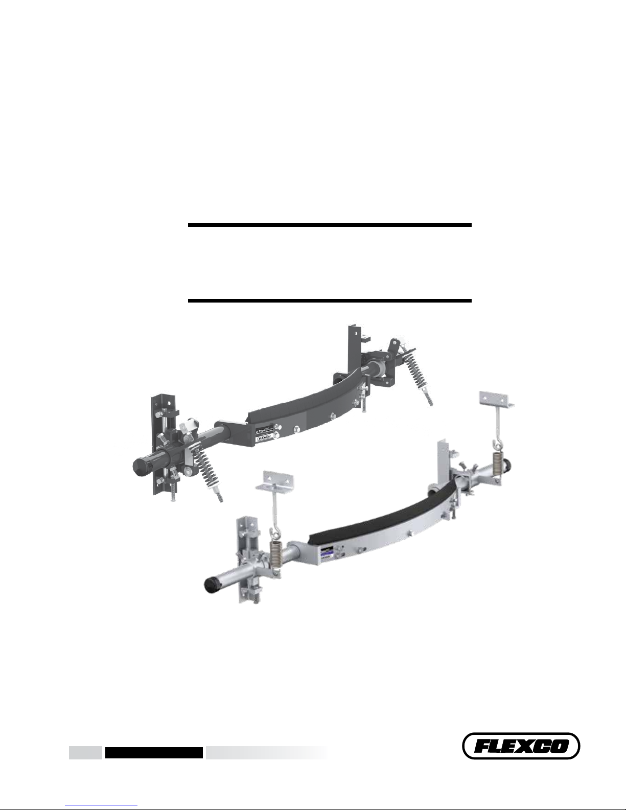
U-Type®Secondary Belt Cleaner
Installation, Operation
and Maintenance Manual

2U-Type®Secondary Cleaner
Serial Number:
Purchase Date:
Purchased From:
Installation Date:
Serial number information can be found on the Serial Number Label
included in the Information Packet shipped in the cleaner carton.
is information will be helpful for any future inquiries or questions
about belt cleaner replacement parts, specications or troubleshooting.
U-Type Secondary Cleaner

1
Section 1 - Important Information ...................................................................................................2
1.1 General Introduction...........................................................................................................................2
1.2 User Benets .........................................................................................................................................2
1.3 Service Option......................................................................................................................................2
Section 2 - Safety Considerations and Precautions ..........................................................................3
2.1 Stationary Conveyors...........................................................................................................................3
2.2 Operating Conveyors............................................................................................................................3
Section 3 - Pre-Installation Checks and Options..............................................................................4
3.1 Checklist................................................................................................................................................4
3.2 Optional Installation Accessories.......................................................................................................5
3.3 Correct Blade Installation and Tensioning .......................................................................................6
Section 4 - Installation Instructions..................................................................................................7
Section 5 - Pre-Operation Checklist and Testing............................................................................12
5.1 Pre-Op Checklist................................................................................................................................12
5.2 Test Run the Conveyor ......................................................................................................................12
Section 6 - Maintenance...................................................................................................................13
6.1 New Installation Inspection..............................................................................................................13
6.2 Routine Visual Inspection.................................................................................................................13
6.3 Routine Physical Inspection .............................................................................................................13
6.4 Blade Replacement Instructions.......................................................................................................14
6.5 Maintenance Log................................................................................................................................16
6.6 Cleaner Maintenance Checklist........................................................................................................17
Section 7 - Troubleshooting ............................................................................................................18
Section 8 - Specications and CAD Drawing .................................................................................19
8.1 Specs and Guidelines .........................................................................................................................19
8.2 CAD Drawing - Cleaners with UST Tensioners ............................................................................20
8.3 CAD Drawing - Cleaners with J-Bolt Tensioners..........................................................................21
Section 9 - Replacement Parts .........................................................................................................22
9.1 Replacement Parts and Poles (Mild Steel) ......................................................................................23
9.2 Replacement Parts and Poles (Stainless Steel)................................................................................24
9.3 Replacement Blades ...........................................................................................................................25
Section 10 - Other Flexco Conveyor Products ................................................................................26
Table of Contents

2U-Type®Secondary Cleaner
We at Flexco are very pleased that you have selected a U-Type® Secondary Cleaner for your conveyor system.
is manual will help you to understand the operation of this product and assist you in making it work up to its
maximum eciency over its lifetime of service.
It is essential for safe and ecient operation that the information and guidelines presented be properly
understood and implemented. is manual will provide safety precautions, installation instructions,
maintenance procedures and troubleshooting tips.
If, however, you have any questions or problems that are not covered, please contact your eld representative or
our Customer Service Department:
Customer Service: 1-800-541-8028
Visit www.exco.com for other Flexco locations and products.
Please read this manual thoroughly and pass it on to any others who will be directly responsible for installation,
operation and maintenance of this cleaner. While we have tried to make the installation and service tasks as easy
and simple as possible, it does however require correct installation and regular inspections and adjustments
to maintain top working condition.
1.2 User Benets
Correct installation and regular maintenance will provide the following benets for your operation:
• Reduced conveyor downtime
• Reduced man-hour labor
• Lower maintenance budget costs
• Increased service life for the belt cleaner and other conveyor components
1.3 Service Option
e U-Type Secondary Cleaner is designed to be easily installed and serviced by your on-site personnel.
However, if you would prefer complete turn-key factory service, please contact your local Flexco Field
Representative.
Section 1 - Important Information
1.1 General Introduction
3
Before installing and operating the U-Type® Secondary Cleaner, it is important to review and understand the following
safety information.
ere are set-up, maintenance and operational activities involving both stationary and operating conveyors. Each
case has a safety protocol.
2.1 Stationary Conveyors
e following activities are performed on stationary conveyors:
• Installation • Blade replacement • Repairs
• Tension adjustments • Cleaning
DANGER
DANGER
WARNING
WARNING
WARNING
!
!
!
!
!
It is imperative that OSHA/MSHA Lockout/Tagout
(LOTO) regulations, 29 CFR 1910.147, be followed before
undertaking the preceding activities. Failure to use LOTO
exposes workers to uncontrolled behavior of the belt
cleaner caused by movement of the conveyor belt. Severe
injury or death can result.
Before working:
• Lockout/Tagout the conveyor power source
• Disengage any takeups
• Clear the conveyor belt or clamp securely
in place
Use Personal Protective Equipment (PPE):
• Safety eyewear
• Hardhats
• Safety footwear
Close quarters, springs and heavy components
create a worksite that compromises a worker’s
eyes, feet and skull.
PPE must be worn to control the foreseeable
hazards associated with conveyor belt cleaners.
Serious injuries can be avoided.
2.2 Operating Conveyors
ere are two routine tasks that must be performed while the conveyor is running:
• Inspection of the cleaning performance
• Dynamic troubleshooting
Every belt cleaner is an in-running nip hazard. Never
touch or prod an operating cleaner. Cleaner hazards
cause instantaneous amputation and entrapment.
Never adjust anything on an operating cleaner.
Unforseeable belt projections and tears can catch
on cleaners and cause violent movements of the
cleaner structure. Flailing hardware can cause
serious injury or death.
Belt cleaners can become projectile hazards.
Stay as far from the cleaner as practical and use
safety eyewear and headgear. Missiles can inict
serious injury.
Section 2 - Safety Considerations and Precautions

4U-Type®Secondary Cleaner
• Check that the cleaner size is correct for the beltline width
• Check the belt cleaner carton and make sure all the parts are included
• Review the “Tools Needed” list on the top of the installation instructions
• Check the conveyor site:
- Will the cleaner be installed on a chute
- Is the install on an open head pulley requiring mounting structure
(see 3.2 - Optional Installation Accessories)
3.1 Checklist
Section 3 - Pre-Installation Checks and Options
Versatile, adjustable brackets that can be mounted on the conveyor structure so the U-Type cleaner can be quickly
and easily bolted into place. Pole extenders are also available for wide, non-standard conveyor structures.
Optional Installation Accessories
DESCRIPTION
ORDERING
NUMBER
ITEM
CODE
WT.
KGS.
WT.
LBS.
Mounting Bracket Kit EZS2MBK 75666 6.0 13.0
60 mm (2-3/8”) Pole
Extender Kit RAPEK 77423 8.0 18.0
73 mm (2-7/8”) Pole
Extender Kit MAPEK 76024 10.0 21.9
75666
Mounting Bracket Kit
(includes 1 le and 1 right bracket)
76024
Pole Extender Kit
(includes 2 pole extenders)
• For cleaner sizes 1800mm (72") and larger
• Provides 750mm (30”) of extended pole length
3.2 Optional Installation Accessories
5
Section 3 - Pre-Installation Checks and Options
3.3 Correct Blade Installation and Tensioning
For optimal cleaning eciency and long wear life, the U-Type® blade must be located and tensioned correctly on
the belt. If the cleaner pole is in the wrong location the performance of the new blade may be adversely aected.
See “Possible Problems” below. For tensioning, please follow these instructions.
Correct Tensioning:
Correct tension is determined and set by blade width. Check the information provided with the tensioner being used
or consult the installation instructions.
Possible Problems:
• Pole location too low - e initial cleaning will be
concentrated in the center of the belt, failing to
clean the outer edges eciently.
• Pole location too high - e intial cleaning will be
concentrated to the outer edges of the belt, failing
to eciently clean the center of the belt.
• Tension too low - Without the optimal tension,
the cleaning eciency is reduced and chatter or
bouncing of the blade can occur.
• Tension too high - Although the cleaning may
appear ecient, accelerated blade wear may
occur; and in some cases less eciency on the
outer edges of the belt, which could result in
increased belt wear.
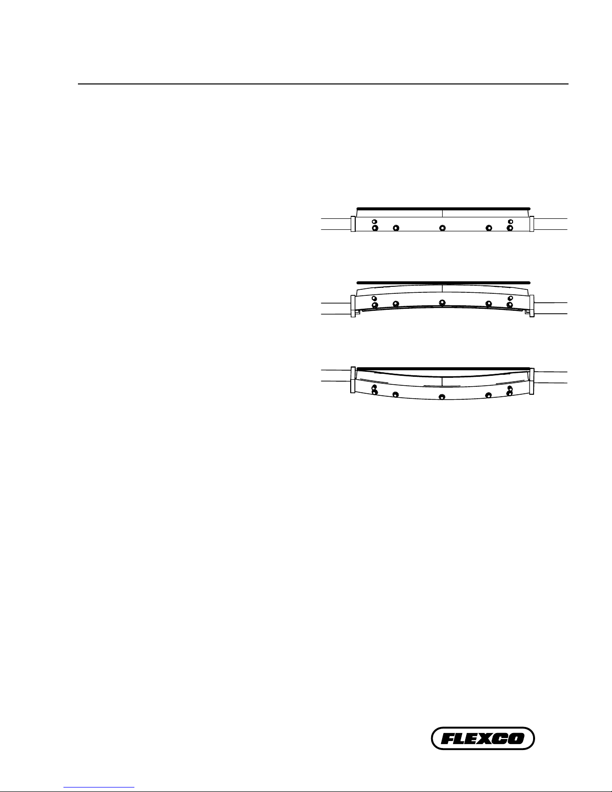
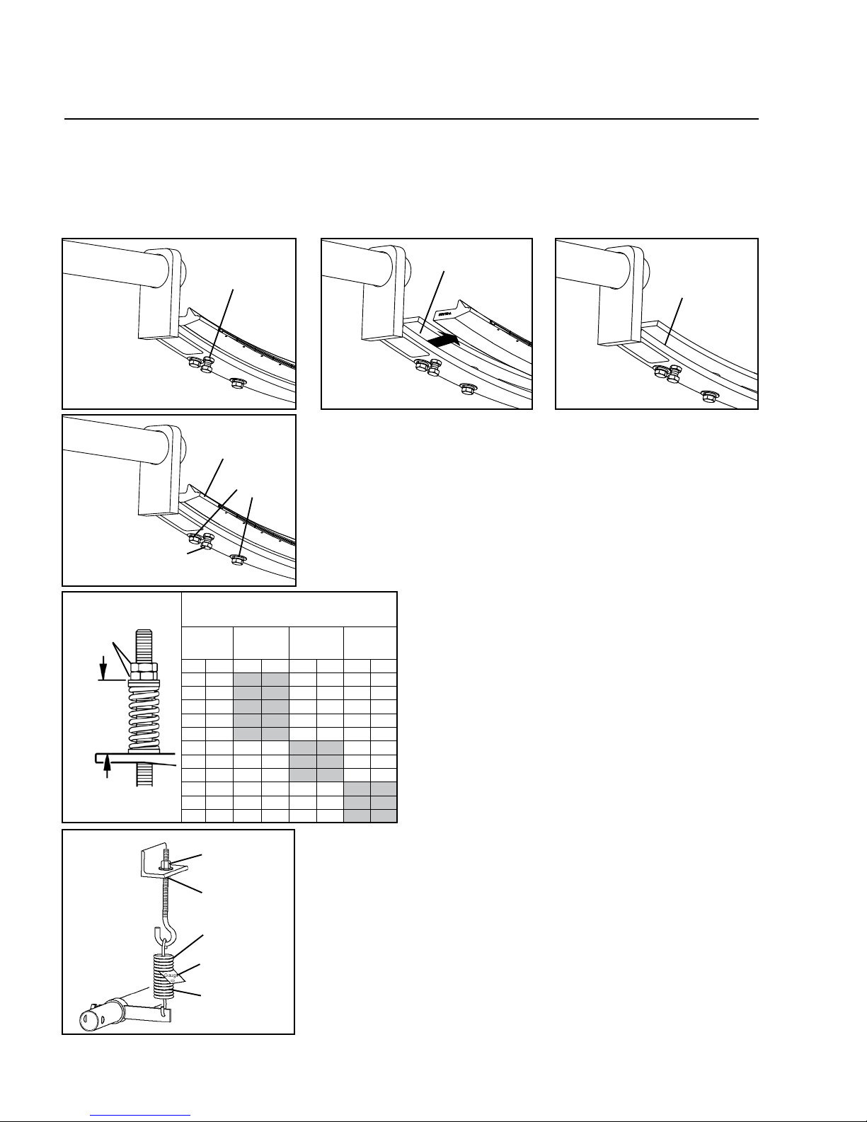
Correct Pole Location:
When the blade contacts the belt (before tensioning)
there should be blade-to-belt contact across the
entire blade (Fig. 1). If contact is more in the center
with a gap on the outer edges, the pole will need to
be raised until full contact is achieved (Fig. 2). If
contact is more on the outer edges with a gap in the
center, the pole will need to be lowered until full
contact is achieved (Fig. 3).
Fig. 1
Fig. 2
Fig. 3
6U-Type®Secondary Cleaner
Section 4 - Installation Instructions
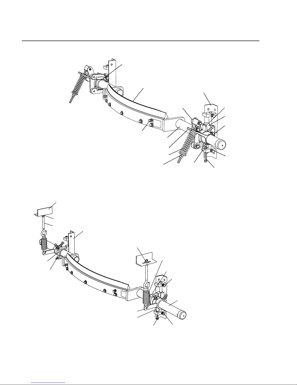
4.1 U-Type® Secondary Cleaner
U-Type with J-Bolt Tensioner
Parts List (Stainless Steel only)
J-Bolt Jam Nut
Adjusting Bolt &
Adjusting Bolt
Lock Nut
Mounting Bracket
Tension Spring
J-Bolt
Pole
Adjusting Arm
Stop Collar
Pole Bearing
Retaining Pin
& Spring Clip
Bearing Mount
Mounting Bracket
Set Screw &
Lock Nut
Mounting Bracket
Set Screw &
Lock Nut
Tensioner Adjusting Nut
J-Bolt Mount
Blade Retaining Screw
& Lock Nut
Mounting Bracket
Compression Spring
Pole
Torque Arm
Pole Bearing
Adjusting Bolt &
Adjusting Bolt
Lock Nut
Pivot Shaft Bracket
Slide Plate
Set Screw &
Lock Nut
Tension Adjusting Nut
Blade
Slide Plate
Mounting Bracket
Set Screw &
Lock Nut
Torque Arm
Set Screw
& Lock Nut
U-Type with UST Tensioner
Parts List
Stop Collar
7
Tools Needed:
• Tape measure
• 19mm (3/4") wrench
• Ratchet with 19mm (3/4") socket
• Screwdriver
• (2) 150mm (6") C-clamps (optional for
locating mounting brackets)
• Level (optional for locating belt height)
• Permanent marker
• Cutting torch and/or welder
• Square (for setting blade parallel to belt)
Before You Begin:
• Double-check the blade type needed for your application:
F-Blade - for mechanically spliced belts.
C-Blade - for Flexco Solid Plate mechanically spliced and
vulcanized belts.
V-Blade - for vulcanized belts. Can be used with mechanical
splices (solid bolt fasteners) that are recessed (skived) into the
belt cover (bolts must be ground on plate fasteners).
• For chute mounting it is necessary to cut an access hole. See
access hole dimensions at right.
• Follow all safety precautions when using a cutting torch.
• If welding, protect all fastener threads from weld spatter.
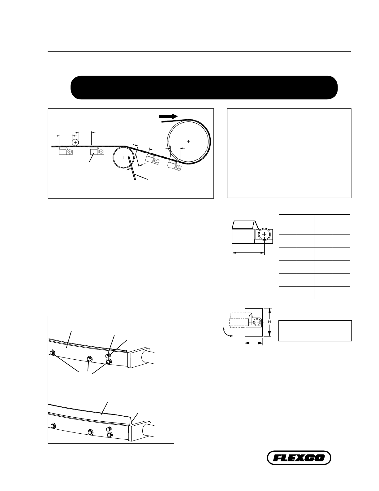
• For cleaner clearance requirements see chart at right.
Cleaner Location Options
Belt Direction
A
C C
U-Type Cleaner B
Head Pulley
Chute wall
150-200mm
(6-8”)
Min.
150-200mm
(6-8")
Min.
150-200mm
(6-8”)
Min.
100mm (4")
Min.
150-200mm
(6-8”)
Min.
(6”)
150
mm
Chute Mounting Access Hole
Dimensions
Belt Width H Dimension
450-1050mm (18" - 42") 200mm (8")
1200-2400mm (48" - 96") 250mm (10")
CLEARANCE
Section 4 - Installation Instructions
4.1 U-Type® Secondary Cleaner
Physically lock out and tag the conveyor at the power source
before you begin cleaner installation.
Install the blade in the pole:
a. Loosen both locknuts on the blade retaining bolts.Turn blade
retaining bolts out 8 turns (Fig. a).
b. Loosen (but do not remove) all plate retaining bolts (Fig. b).
c. Install the new blade as shown in Fig. b. e ap on the blade
should face away from bladeholder screws.
d. Center the blade in the holder.
e. Tighten all plate retaining screws.
f. Tighten blade retaining screws 8 turns and tighten the blade
retaining screw locknuts.
Blade
retaining
bolt
Plate
retaining
bolts
Center blade
in holder
Blade holder
Flap facing away
from bladeholder
bolts
Locknut
Fig. a
Fig. b
Cleaner Clearance Requirements
U Cleaner Size Clearance
mm in. mm in.
450 18" 155 6
600 24" 180 7
750 30" 205 8
900 36" 205 8
1050 42" 235 9 1/4
1200 48" 270 10 1/2
1350 54" 275 10 3/4
1500 60" 275 10 3/4
1800 72" 275 10 3/4
2100 84" 275 10 3/4
2400 96” 275 10 3/4
8U-Type®Secondary Cleaner
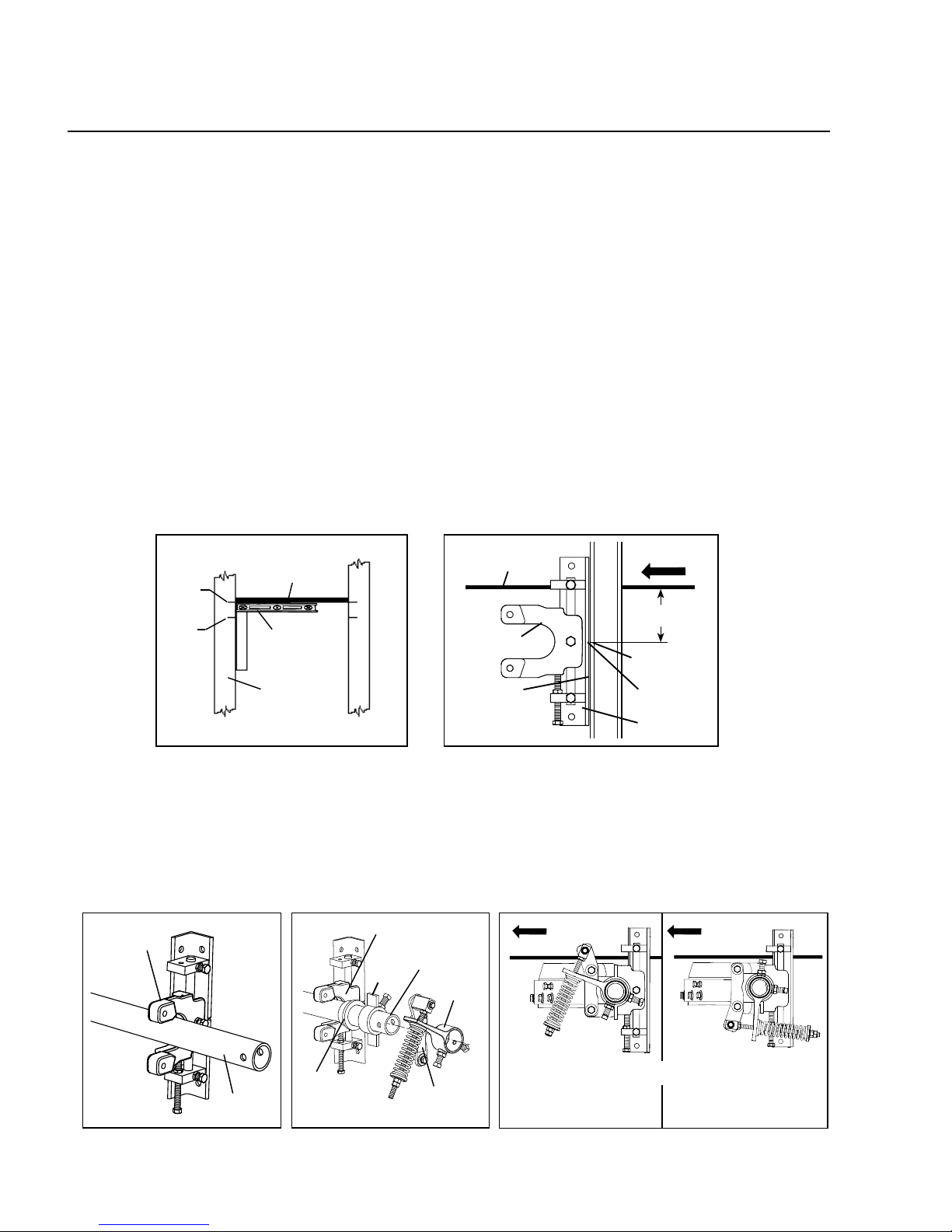
3U. Install the cleaner pole into the slider plates.
a. Set pole ends into slider plate on both sides (Fig. 3Ua).
b. Slide pole bearings onto both ends of the pole with ange facing away from the belt (Fig. 3Ub).
c. Slide stop collar onto both ends of the pole (Fig. 3Ub). Do not tighten at this time.
d. Slide torque arms onto both ends of pole and attach both pivot sha brackets to slider plates (Fig. 3Ub).
Blade and torque arm must face either in the direction of belt travel (Fig. 3Uc), or if clearance is an issue,
switch to rotated tensioner conguration and assemble as shown (Fig. 3Ud).
e. Move slider plate to bottom of bracket to allow blade to rotate up into position in the next steps.
Fig. 3Ua
Repeat at
other end
Repeat at
other end
Slider Plate
Pole
Pole Bearing
(flange facing out)
Pole
- OR -
Fig. 3Ub
Slider Plate
Torque
Arm
Stop
Collar
Pivot Shaft
Bracket
Belt Direction Belt Direction
Blade and torque arm
must face in the direction
of belt travel
If clearance is an issue
switch to rotated tensioner
configuration and assemble
as shown.
Section 4 - Installation Instructions
4.1 U-Type® Secondary Cleaner
Fig. 3UdFig. 3Uc
Fig. 2Ua
2U. Install mounting brackets.
a. Using a level, lightly raise return side belt (take out cupping or sagging on edges) to nd belt's true parallel path to
the structure; and mark reference point #1 on structure. Measure down 75mm (3”) from reference point #1 and
mark reference point #2 (Fig. 2Ua). Make sure brackets are the same distance away from head pulley or a reference
point on both sides of the structure. If there is no structure to mount to, install mounting bracket kit rst.
b. Position mounting brackets so centerline marks on brackets are in line with reference points #2 on the structure
(Fig. 2Ub).
c. Clamp or weld into position.
Return
Side Belt Belt Direction
Mounting
Bracket
Ref.
Point #1
Level
Return
Side Belt
Structure
Right
Side
Left
Side
#1
#2
Ref.
Point #2 Ref.
Point #2
Fig. 2Ub
Centerline on
Bracket
Bracket flush
to structure or
mounting kit
Slider Plate
3" (75mm)
UST Tensioner Instructions
1. Choose conveyor location where cleaner will be installed.
e U-Type may be positioned at any spot from where belt leaves head pulley on down the conveyor line (see
positions A to B). If a chute area is too small due to a snub pulley, it may be necessary to mount cleaner behind
chute (see position C). In chute applications a minimum of 150-200mm (6”-8”) is required between cleaner and
chute wall to prevent clogging of material.
NOTE: For U-Type cleaners using UST Tensioners, proceed to Steps 2U - 7U.
For U-Types using J-Bolt Tensioners, skip ahead to Steps 2J - 8J on Page 10.

9
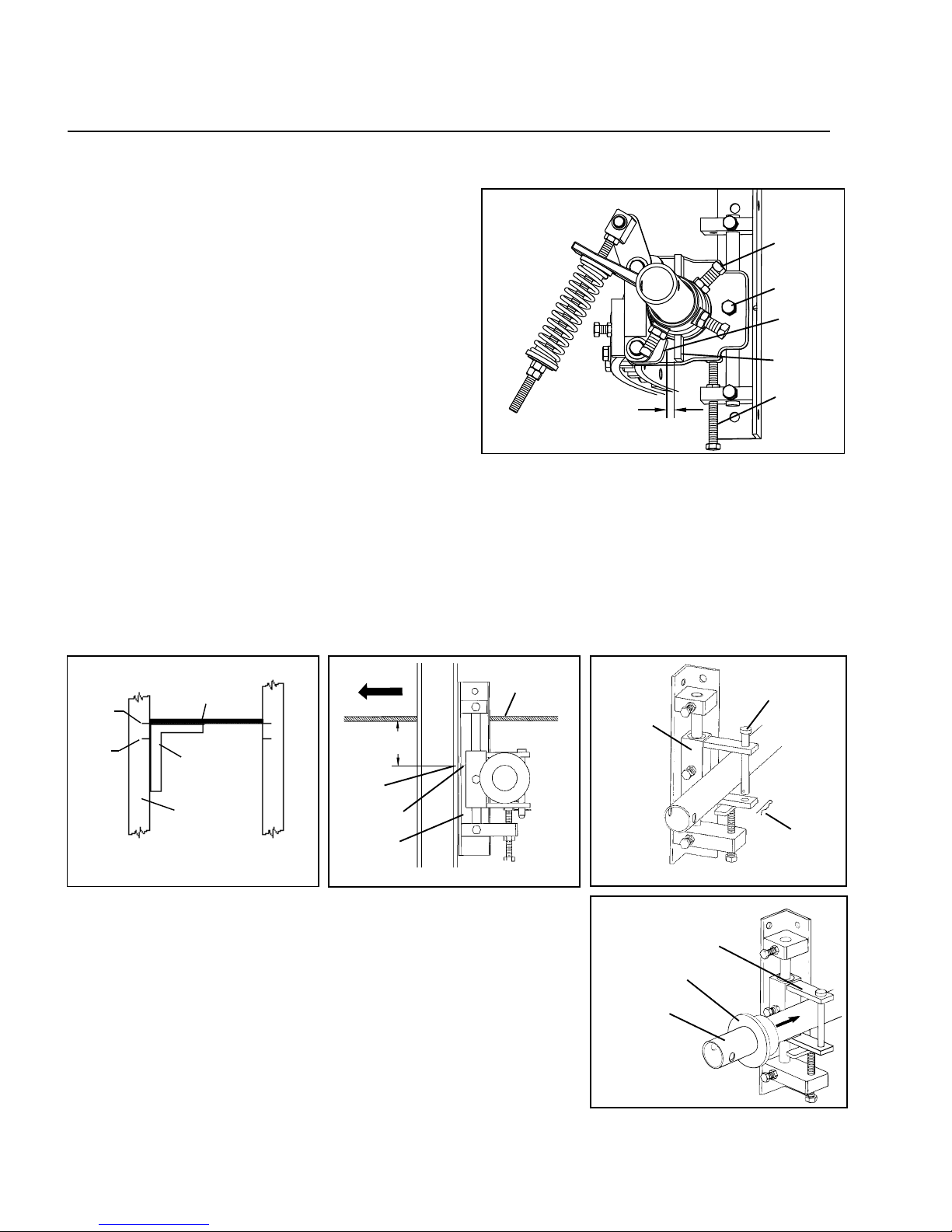
4U. Tighten torque arm set screws.
a. Spring tension nuts should be moved near the end of the threaded rod. Insert a screwdriver or small rod
through holes on end of cleaner pole. Pushing on screwdriver or rod, rotate cleaner blade into a position
with pole parallel to belt (Fig. 4Ua). Blade should not be touching belt at this time. e gap between the torque
arm and pivot block should be approximately 50mm (2").
b. Center the blade to the belt and make sure torque arm, stop collar, bearing and slide plate are tight together on
both sides. en tighten stop collar set screw and lock nut with stop collar touching top of bearing mount stop
to hold blade parallel to belt, and remove screwdriver or rod.
c. Push torque arm down to contact the spring and tighten the torque arm set screws and lock nuts on both sides
of the cleaner (Fig. 4Ub).
6U. Set the blade tension.
a. Set spring length to determined length (Fig. 6U).
Tighten spring tension nuts on threaded rod.
IMPORTANT: Always be sure there is uniform
contact between blade and belt.
b. If blade is not in full contact with belt at edges
and center, either raise or lower pole position of
cleaner and reapply tension.
c. Please note, when fully tensioned there should be
approximately 19mm to 38mm (3/4" to 1-1/2")
of space between the torque arm and pivot block
(Fig. 5U).
5U. Adjust the blade to the belt.
a. Loosen slide plate set screws and lock nuts. Adjust by
turning adjusting bolts either up or down (Fig. 5U).
b. Adjust blade either up or down until both blade ends and
the center make full contact with belt. If possible, adjust
both sides of the cleaner up to the belt at the same time
for even blade contact across belt (reduces chance of
overtensioning on one side).
IMPORTANT: In some cases, due to irregular belt wear
or cupping, it may be necessary to make nal adjustments
independently on both sides.
c. Tighten lock nuts on adjusting bolts to secure blade in
correct position. Also tighten slide plate set screws and
lock nuts.
Adjusting
Bolt
Fig. 5U
Slide Plate Set Screw
and Lock Nut
Lock Nut
Fig. 4Ua Fig. 4Ub
50mm (2”) gap
before tensioning
Spring tensioner
nuts at end of
threaded rod
Screwdriver
or small rod
Parallel
with belt
Stop collar
set screw
and lock nut
Stop collar
touching bearing
mount stop
No blade contact
with belt
Full blade
contact with belt
Tighten stop
collar set
screw and lock
nut to hold
blade parallel
to belt.
Section 4 - Installation Instructions
4.1 U-Type® Secondary Cleaner with UST Tensioner (cont.)
Push torque arm down
to contact spring; tighten
torque arm set screws
Top of
washer
to top of
torque arm
Adjusting
Nuts
Fig. 6U
19mm to 38mm
(3/4” to 1-1/2”)
gap
2
1
Torque arm
set screws
BELT
Spring Length Chart
(for Cleaners with UST Tensioners)
Blade
Width
Purple
Spring
Silver
Spring
White
Spring
mm in. mm in. mm in. mm in.
450 18 154 6 1/8 160 6 3/8 162 6 3/8
600 24 148 5 7/8 148 6 1/4 160 6 1/4
750 30 140 5 1/2 156 6 1/8 158 6 1/4
900 36 136 5 3/8 152 6 156 6 1/8
1050 42 128 5 150 5 7/8 154 6 1/8
1200 48 N/A N/A 146 5 3/4 152 6
1350 54 N/A N/A 142 5 5/8 150 5 7/8
1500 60 N/A N/A 140 5 1/2 150 5 7/8
1800 72 N/A N/A N/A N/A 140 5 1/2
2100 84 N/A N/A N/A N/A 136 5 3/8
2400 96 N/A N/A N/A N/A 132 5 1/4
10 U-Type®Secondary Cleaner
Fig. 3Ja
3J. Install cleaner pole into bearing mounts in both mounting brackets.
a. Remove nylon bearings from both bearing mounts. Remove spring clip
and pull retaining pin out of one bearing mount. Slide cleaner pole into
bearing mount on the opposite side and then position it into bearing
mount where retaining pin was removed. Reinsert retaining pin and
lock into place with spring clip (Fig. 3Ja).
b. Slide a nylon bearing onto each pole end with anged end facing away
from belt. Nylon bearing will t snugly into bearing mount (Fig. 3Jb).
c. Position the pole so that blade is centered to belt. With blade centered,
draw a line around pole at nylon bearing. is line can be used as a
reference point to ensure the pole/blade remains centered to belt while
other steps are completed.
Nylon Bearing
Pole
Fig. 3Jb
Retaining Pin
Spring
Clip
Bearing
Mount
Bearing Mount
2J. Install the mounting brackets onto the structure.
a. Using a square, lightly raise return side belt (take out cupping or sagging on edges) to nd belt's true parallel
path to the structure; and mark reference point #1 on the structure on both sides of the conveyor. Measure
down 84mm (3-3/8”) from reference point #1 on both sides and mark reference point #2 (Fig. 2Ja).
b. Position the mounting brackets so the centerline marks on the brackets are in line with reference points #2 on
the structure (Fig. 2Jb).
c. Clamp or weld into position.
J-Bolt Tensioner Instructions - For Stainless Steel Cleaners
Return
Side Belt
Belt Direction
Mounting
Bracket
Ref.
Point #2
Fig. 2Jb
Centerline on
Bracket
Fig. 2Ja
Ref.
Point #1
16" x 24"
Square
Return
Side Belt
Structure
Right
Side
Left
Side
#1
#2
Ref.
Point #2
3-3/8"
(84mm)
7U. Set the blade travel stop.
Set both stop collars to a clearance of 6mm (1/4”)
between stop collar and bottom bearing mount stop for
UV and UC cleaners, or 13mm (1/2”) for UF cleaners
(Fig. 7U). is is to prevent blade from moving into belt.
Tighten set screws and lock nuts.
Bearing
Mount Stop
Slide Plate
Set Screw
Adjusting
Bolt
Stop Collar
Set Screw
Stop Collar
Clearance
UV-UC: 6mm (1/4”)
UF: 13mm (1/2”)
4.2 U-Type SS J-Bolt Cleaner
4.1 U-Type® Secondary Cleaner with UST Tensioner (cont.)
Section 4 - Installation Instructions
Fig. 7U

11
Fig. 4Jb
Fig. 4Ja
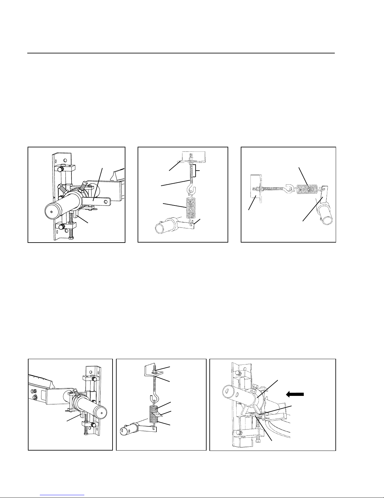
4J. Install the stop collars.
a. Slide one stop collar onto the most convenient pole end (Fig. 4Ja).
b. Insert a screwdriver or small rod into hole on end of cleaner pole. Pushing on the rod, move blade
into a positon parallel to belt (Fig. 4Jb). Blade should not be touching belt at this time.
c. Tighten stop collar set screw and lock nut to hold blade parallel to belt and remove screwdriver or rod.
d. Install second stop collar on other pole end. Do not tighten set screw and lock nut at this time.
Stop Collar Set Screw
and Lock Nut
Screwdriver
or Small Rod
Blade
No contact with belt
Stop Collar
Adjusting Bolt
5J. Adjust blade to belt.
a. Loosen bearing mount set screws and lock nuts. Adjustments will be
made by turning adjusting bolts either up or down (Fig. 5J).
b. Adjust blade either up or down until both blade ends and the center
make full contact with belt.
IMPORTANT: In some cases, due to irregular belt wear or cupping, it may
be necessary to make nal adjustments independently on both sides.
c. Tighten lock nuts on adjusting bolts to secure blade in correct position.
Also tighten bearing mount set screws and lock nuts.
Fig. 5J
Bearing Mount Set
Screw and Lock Nut
4.2 U-Type® Stainless Steel J-Bolt Cleaner (cont.)
Section 4 - Installation Instructions
12 U-Type®Secondary Cleaner
Fig. 8J
Tensioner
Adjusting Nut
J-Bolt Jam Nut
Tension Spring
Clearance .030"
Between Coils
Spring Tension
Gauge
9J. Set the blade travel stop.
Set both stop collars to a clearance of 6mm (1/4”) for UV and UC cleaners, or 13mm (1/2”) for UF cleaners, from
bearing mount stops (Fig. 9J). is is to prevent blade from moving into belt. Tighten set screws and lock nuts.
7J. Set up stop collar and assemble opposite tensioning system.
a. Loosen stop collar (Fig. 7J).
b. Slide the second adjusting arm on pole end; assemble and mount tensioning system.
8J. Set the spring tension.
a. Loosen J-bolt jam nuts and turn tensioner adjusting nuts until both springs have a clearance of about
.030" between all coils (use Spring Tension Gauge included in installation instruction packet.) (Fig. 8J).
IMPORTANT: Always be sure there is uniform contact between blade and belt.
b. If blade is not in full contact with belt at edges and center, either raise or lower pole position of cleaner
and reapply tension.
Fig. 7J
Stop Collar
Clearance 6mm (1/4”)
for UV and UC;
13mm (1/2”) for UF
Fig. 9J Bearing
Mount Stop
Stop Collar
Belt Direction
4.2 U-Type® SS J-Bolt Cleaner (cont.)
Section 4 - Installation Instructions
6J. Mount the tensioning system.
a. Slide one adjusting arm onto pole end with stop collar that was not tightened (Fig. 6Ja).
b. Assemble tension spring and J-bolt mount to adjusting arm. Locate position for J-bolt mount (Fig. 6Jb).
IMPORTANT: Allow at least 50mm (2”) of upward movement for J-bolt end for future adjustment.
c. e J-bolt mount can be mounted in any position (360 degrees) around pole. e only requirement is
that J-bolt and spring remain perpendicular to adjusting arm (Fig. 6Jc).
d. Weld or bolt J-bolt mount into position.
e. Tighten adjusting arm set screw and lock nut to secure position on pole.
f. Adjust J-bolt to apply light tension on tension spring.
Fig. 6Ja Fig. 6Jc
J-Bolt Mount
Tension Spring
Adjusting Arm
Adjusting Arm
Fig. 6Jb
Tension
Spring
J-Bolt
J-Bolt Mount (50mm (2”)
Upward
Movement
Adjusting Arm
Stop Collar

13
Section 5 - Pre-Operation Checklist and Testing
• Run the conveyor for at least 15 minutes and inspect the cleaning performance
• Check the tensioner spring for recommended length (proper tensioning)
• Make adjustments as necessary
• Recheck that all fasteners are tightened properly
• Add pole caps
• Apply all supplied labels to the cleaner
• Check the blade location on the belt
• Be sure that all installation materials and tools have been
removed from the belt and the conveyor area
NOTE: Observing the cleaner when it is running and performing properly will help to detect
problems or when adjustments are needed later.
5.1 Pre-Op Checklist
5.2 Test Run the Conveyor

14 U-Type®Secondary Cleaner
Section 6 - Maintenance
Flexco belt cleaners are designed to operate with minimum maintenance. However, to maintain superior
performance some service is required. When the cleaner is installed a regular maintenance program should be
set up. is program will ensure that the cleaner operates at optimal eciency and problems can be identied
and xed before the cleaner stops working.
All safety procedures for inspection of equipment (stationary or operating) must be observed. e U-Type Belt
Cleaner operates at the discharge end of the conveyor and is in direct contact with the moving belt. Only visual
observations can be made while the belt is running. Service tasks can be done only with the conveyor stopped
and by observing the correct lockout/tagout procedures.
6.1 New Installation Inspection
Aer the new cleaner has run for a few days a visual inspection should be made to ensure the cleaner is
performing properly. Make adjustments as needed.
6.2 Routine Visual Inspection (every 2-4 weeks)
A visual inspection of the cleaner and belt should look for:
• If spring length is the correct length for optimal tensioning
• If spring gap is correct for optimal tensioning (for J-Bolt tensioners)
• If belt looks clean or if there are areas that are dirty
• If blade is worn out and needs to be replaced
• If there is damage to the blade or other cleaner components
• If fugitive material is built up on cleaner or in the transfer area
• If there is cover damage to the belt
• If there is vibration or bouncing of the cleaner on the belt
• If a snub pulley is used, a check should be made for material buildup on the pulley
• Signicant signs of carryback
•
• If any of the above conditions exist, a determination should be made on when the conveyor can
be stopped for cleaner maintenance.
6.3 Routine Physical Inspection (every 6-8 weeks)
When the conveyor is not in operation and properly locked and tagged out, a physical inspection of the
cleaner to perform the following tasks:
• Clean material buildup o of the cleaner blade and pole
• Closely inspect the blade for wear and any damage. Replace if needed.
• Ensure full blade to belt contact
• Inspect the cleaner pole for damage
• Inspect all fasteners for tightness and wear. Tighten or replace as needed.
• Replace any worn or damaged components
• Check the tension of the cleaner blade to the belt. Adjust the tension if necessary using the chart
on the cleaner or the one on Page 16. For J-bolt Tensioners, use the spring tension gauge to set a
.7mm (.030”) gap between spring coils.
• When maintenance tasks are completed, test run the conveyor to ensure the cleaner is
performing properly

15
U-Type Secondary Belt Cleaners
1. Release the blade tension.
UST Spring Tensioner: Loosen the tension
adjusting nuts on the tensioner pivot rods,
allowing the pole to rotate the blade down
(Fig. 1a).
J-Bolt Tensioner: Loosen both J-bolt jam
nuts and remove the tensioner adjusting
nuts and at washers, allowing the pole to
rotate against the stop collar and the blade
to rotate down (Fig. 1b).
Double check the blade type needed for your application:
F-Blade - for mechanically-spliced belts
C-Blade - for Flexco Solid Plate mechanically spliced and
vulcanized belts
V-Blade - for vulcanized belts. Can be used with mechanical splices
(solid bolt fasteners) that are recessed (skived) into the belt cover
(bolts must be ground on plate fasteners)
Fig. 1b
6.4 Blade Replacement Instructions
Tools Needed:
- Tape measure
- 19mm (3/4") wrench
- Wire brush
U-Type Replacement Blades
V-Blade
C-Blade
F-Blade
Blade
Blade
Adjusting Nuts
Fig. 1a
Pivot Rod
J-Bolt Jam
Nut
Tensioner
Adjusting Nut
Flat Washer
Section 6 - Maintenance
Physically lock out and tag the conveyor at the power source before you
begin cleaner installation.
U-Type with J-Bolt Tensioner
U-Type with UST Tensioner
16 U-Type®Secondary Cleaner
3. Install the new blade.
a. Center the blade in the holder (Fig. 3).
b. Tighten all plate retaining screws.
c. Tighten blade retaining screws 8 turns and tighten the blade
retaining screw locknuts (Fig 3).
5. Inspect for full blade contact to the belt. Important - Always be
sure there is uniform contact between the blade and the belt. If the
blade is not in full contact with the belt at the edges and center, raise
or lower the pole position of the cleaner and reapply the tension (See
Installation Instructions).
Section 6 - Maintenance
2. Remove the worn blade.
a. Loosen both locknuts on the blade retaining screws. Turn blade retaining screws out 8 turns (Fig. 2a).
b. Loosen or remove all plate retaining screws.
c. From one end, insert a screwdriver under the blade and lightly pry the blade up and out of the blade
holder (Fig. 2b). Once the blade breaks free, pull it out by hand.
c. Remove the blade from the holder and clean material buildup from holder with a wire brush (Fig. 2c).
Clean buildup
from blade holder
Loosen both
locknuts and blade
retaining screws
Insert
screwdriver,
pry blade up
Fig. 2a Fig. 2b Fig. 2c
Tighten both blade
retaining screws
and locknuts
Plate
retaining
screws
Center new blade
in blade holder
Fig. 3
Tensioner
Adjusting Nut
J Bolt Jam Nut
Tension Spring
Clearance .030"
between coils
Fig. 4b
Spring Tension
Gauge
4. Reset the blade tension.
UST Spring Tensioner: Refer to the chart for the spring
length required for the belt width. Lightly pull the pivot
arm toward the end of the torque arm slot nearest the
pole and turn the adjusting nuts until the required
spring length is achieved (Fig. 4a). NOTE: e chart
is also on the cleaner’s pivot sha bracket for future
reference for retensioning maintenance. Reference
Section 4 (Cleaner Installation Instructions) on page 6.
J-Bolt Tensioner: Rotate the pole and insert the J bolts
through the J bolt mount holes and install the at
washers and tensioner adjusting nuts. Turn the tensioner
adjusting nuts until a .7mm (.030”) gap (use Spring
Tension Gauge included with cleaner) appears between
all coils of the tension spring (Fig. 4b). Lock both J bolt
jam nuts.
Test run the cleaner. Run the conveyor for at least 15 minutes and
inspect the cleaning performance. Check the spring length for proper
tensioning. Make adjustments as necessary.
Top of
washer
to top of
torque arm
Adjusting
Nuts
Spring Length Chart
(for Cleaners with UST Tensioners)
Blade
Width
Purple
Spring
Silver
Spring
White
Spring
mm in. mm in. mm in. mm in.
450 18 154 6 1/8 160 6 3/8 162 6 3/8
600 24 148 5 7/8 148 6 1/4 160 6 1/4
750 30 140 5 1/2 156 6 1/8 158 6 1/4
900 36 136 5 3/8 152 6 156 6 1/8
1050 42 128 5 150 5 7/8 154 6 1/8
1200 48 N/A N/A 146 5 3/4 152 6
1350 54 N/A N/A 142 5 5/8 150 5 7/8
1500 60 N/A N/A 140 5 1/2 150 5 7/8
1800 72 N/A N/A N/A N/A 140 5 1/2
2100 84 N/A N/A N/A N/A 136 5 3/8
2400 96 N/A N/A N/A N/A 132 5 1/4
Fig. 4a

17
6.5 Maintenance Log
Conveyor Name/No.
Date: Work done by: Service Quote #
Activity:
Date: Work done by: Service Quote #
Activity:
Date: Work done by: Service Quote #
Activity:
Date: Work done by: Service Quote #
Activity:
Date: Work done by: Service Quote #
Activity:
Date: Work done by: Service Quote #
Activity:
Date: Work done by: Service Quote #
Activity:
Section 6 - Maintenance

18 U-Type®Secondary Cleaner
Site: Inspected by: Date:
Belt Cleaner: Serial Number:
Beltline Information:
Beltline Number: Belt Condition:
Belt Width:
Head Pulley Diameter (Belt & Lagging) :Belt Speed: fpm Belt Thickness:
Belt Splice Condition of Splice Number of splices Skived Unskived
Material conveyed
Days per week run Hours per day run
Blade Life:
Date blade installed:
Date blade inspected:
Is blade making complete contact with belt? Yes No
Distance from wear line: LEFT MIDDLE RIGHT
Blade condition:
Good Grooved Smiled Damaged
Measurement of spring: Required Currently
Was Cleaner Adjusted: Yes No
Pole Condition: Good Bent Worn
Lagging: Slide lag Ceramic Rubber Other None
Condition of lagging: Good Bad Other
Cleaner's Overall Performance: ( Rate the following 1 - 5, 1=very poor - 5= very good )
Appearance: Comments:
Location: Comments:
Maintenance: Comments:
Performance: Comments:
Other Comments:
Estimated blade life:
Not contacting belt
18" 24" 30" 36" 42" 48" 54" 60" 72" 84" 96"
(450mm) (600mm) (750mm) (900mm) (1050mm) (1200mm) (1350mm) (1500mm) (1800mm) (2100mm) (2400mm)
Section 6 - Maintenance
6.6 Cleaner Maintenance Checklist
Table of contents
Other Flexco Ultrasonic Jewelry Cleaner manuals


Popular Ultrasonic Jewelry Cleaner manuals by other brands


E-MAG
E-MAG Emmi 06 UVC operating manual

BLACK DECKER
BLACK DECKER BHSB315J instruction manual

Good Way
Good Way IRAM-EX-100 Operating and maintenance instructions

AU Tool
AU Tool C80 user manual

Silvercrest
Silvercrest 365237 2101 operating instructions

Good Way
Good Way AWT-100 Operating and maintenance manual


