Flexco H-Type Primary Cleaner with V-Tips User manual
H-Type®Primary Cleaner with V-Tips
Installation, Operation
and Maintenance Manual
www.flexco.com
www.flexco.com
HV with Bolt Tensioner
HV with PCST Tensioner

H-Type® Primary Cleaner with V-Tips
Purchase Date:______________________________________________________________
Purchased From: ____________________________________________________________
Installation Date: ____________________________________________________________
This information will be helpful for any future inquiries or questions
about belt cleaner replacement parts, specifications or troubleshooting.

3
Table of Contents
Section 1 – Important Information ...........................................................................................................4
1.1 General Introduction ..................................................................................................................................4
1.2 User Benets ................................................................................................................................................4
1.3 Service Option .............................................................................................................................................4
Section 2 – Safety Considerations and Precautions ..................................................................................5
2.1 Stationary Conveyors..................................................................................................................................5
2.2 Operating Conveyors ..................................................................................................................................5
Section 3 – Pre-Installation Checks and Options......................................................................................6
3.1 Checklist .......................................................................................................................................................6
Section 4 – Installation Instructions..........................................................................................................7
4.1 H-Type® Primary Cleaner with V-Tips ..................................................................................................7
4.2a H-Type® Primary Cleaner with V-Tips - Chute Mounting .................................................................8
4.2b H-Type® Primary Cleaner with V-Tips - Open Head Mounting......................................................10
4.3 H-Type® Primary Cleaner with V-Tips - Bolt Tensioner...................................................................11
4.4 H-Type® Primary Cleaner with PCST Tensioner................................................................................13
4.5 H-Type® Primary Cleaner with PCST Tensione- Bolt Tensiner .......................................................15
Section 5 – Cleaner Pole Location Charts ...............................................................................................17
5.1 Pole Location Charts.................................................................................................................................17
Section 6 – Pre-Operation Checklist and Testing....................................................................................20
6.1 Pre-Op Checklist .......................................................................................................................................20
6.2 Test Run the Conveyor..............................................................................................................................20
Section 7 – Maintenance ..........................................................................................................................21
7.1 New Installation Inspection .....................................................................................................................21
7.2 Routine Visual Inspection........................................................................................................................21
7.3 Routine Physical Inspection.....................................................................................................................21
7.4 Blade Replacement Instructions..............................................................................................................22
7.5 Maintenance Log .......................................................................................................................................24
7.6 Cleaner Maintenance Checklist...............................................................................................................25
Section 8 – Troubleshooting ....................................................................................................................26
Section 9 – Specs and CAD Drawings......................................................................................................27
9.1 Specications and Guidelines..................................................................................................................27
9.2 CAD Drawings...........................................................................................................................................28
Section 10 – Replacement Parts List ........................................................................................................31
Section 11 – Other Flexco Conveyor Products........................................................................................35

4H-Type®Primary Cleaner with V-Tips
Section 1 – Important Information
We at Flexco are very pleased that you have selected an H-Type® Primary Cleaner with V-Tips for your
conveyor system.
is manual will help you to understand the operation of this product and assist you in making it work up to
its maximum eciency over its lifetime of service.
It is essential for safe and ecient operation that the information and guidelines presented be properly
understood and implemented. is manual will provide safety precautions, installation instructions,
maintenance procedures and troubleshooting tips.
If, however, you have any questions or problems that are not covered, please visit our web site or contact our
Customer Service Department:
Customer Service: 612-8818-2000
Visit www.flexco.com for other Flexco locations and products.
Please read this manual thoroughly and pass it on to any others who will be directly responsible for
installation, operation and maintenance of this cleaner. While we have tried to make the installation and
service tasks as easy and simple as possible, it does however require correct installation and regular
inspections and adjustments to maintain top working condition.
1.2 User Benets
Correct installation and regular maintenance will provide the following benets for your operation:
• Reduced conveyor downtime
• Reduced man-hour labor
• Lower maintenance budget costs
• Increased service life for the belt cleaner and other conveyor components
1.3 Service Option
e H-Type Primary Cleaner with V-Tips is designed to be easily installed and serviced by your on-site
personnel. However, if you would prefer complete turn-key factory service, please contact your local Flexco
Field Representative.
1.1 General Introduction

5
Before installing and operating the H-Type® Primary Cleaner with V-Tips, it is important to review and understand
the following safety information.
There are set-up, maintenance and operational activities involving both stationary and operating conveyors. Each
case has a safety protocol.
2.1 Stationary Conveyors
The following activities are performed on stationary conveyors:
• Installation • Blade replacement • Repairs
• Tension adjustments • Cleaning
Section 2 – Safety Considerations and Precautions
DANGER
DANGER
WARNING
WARNING
WARNING
!
!
!
!
!
It is imperative that Lockout/Tagout (LOTO) regulations, be
followed before undertaking the preceding activities. Failure
to use LOTO exposes workers to uncontrolled behavior of
the belt cleaner caused by movement of the conveyor belt.
Severe injury or death can result.
Before working:
• Lockout/Tagout the conveyor power source
• Disengage any takeups
• Clear the conveyor belt or clamp securely in place
Use Personal Protective Equipment (PPE):
• Safety eyewear
• Hardhats
• Safety footwear
Close quarters, springs and heavy components
create a worksite that compromises a worker’s eyes,
feet and skull.
PPE must be worn to control the foreseeable
hazards associated with conveyor belt cleaners.
Serious injuries can be avoided.
2.2 Operating Conveyors
There are two routine tasks that must be performed while the conveyor is running:
• Inspection of the cleaning performance
• Dynamic troubleshooting
Every belt cleaner is an in-running nip hazard. Never
touch or prod an operating cleaner. Cleaner hazards
cause instantaneous amputation and entrapment.
Never adjust anything on an operating cleaner.
Unforseeable belt projections and tears can catch
on cleaners and cause violent movements of the
cleaner structure. Flailing hardware can cause
serious injury or death.
Belt cleaners can become projectile hazards. Stay as far
from the cleaner as practical and use safety eyewear and
headgear. Missiles can inflict serious injury.

6H-Type®Primary Cleaner with V-Tips
Section 3 – Pre-installation Checks and Options
• Check that the cleaner size is correct for the beltline width
• Check the belt cleaner carton and make sure all the parts are included
• Review the “Tools Needed” list on the top of the installation instructions
• Check the conveyor site:
- Will the cleaner be installed on a chute
- Is the install on an open head pulley requiring mounting structure
- Are there obstructions that may require cleaner location adjustments
3.1 Checklist

7
4.1 H-Type©Primary Cleaner with V-Tips
Section 4 – Installation Instructions
Before You Begin:
• Installation specs and instructions are based on the assumption
that the conveyor is in its working position (angle). If the
conveyor angle will be different, the cleaner should be installed
per the final position.
• Choose instructions for chute mounting or open head
mounting. For chute mounting it may be necessary to cut
an access hole to allow for installation and inspections.
(See dimensions in Step 7 under Chute Mounting.)
• Follow all safety precautions when using a cutting torch.
• If welding, protect all fastener threads from weld spatter.
Maximum
lump size +
200mm
Chute wall
Space needed to avoid clogging chute
V-Tip Size Pulley Diameter + Belt and Lagging
SS up to 499mm
S 500-799mm
M 800-999mm
L 1000-1199mm
LL 1200-1700mm
Tools Needed
• Tape Measure
• 19mm Wrench
• Ratchet With 19mm Socket
• Adjustable Wrench
• Cutting Torch and/or Welder
• (2) 150mm C-Clamps (For Temporary
Positioning of Mounting Brackets)
• 600mm Level
• Marking Pen
Physically lock out and tag the conveyor at the power source
before you begin cleaner installation.
V-TIP
CUSHION
BEARING BLOCK
POLE
MOUNTING BRACKET
SUSPENSION
ARM
ADJUSTING ARM
ADJUSTING BOLT
8H-Type®Primary Cleaner with V-Tips
4.2a H-Type©Primary Cleaner with V-Tips
Section 4 – Installation Instructions
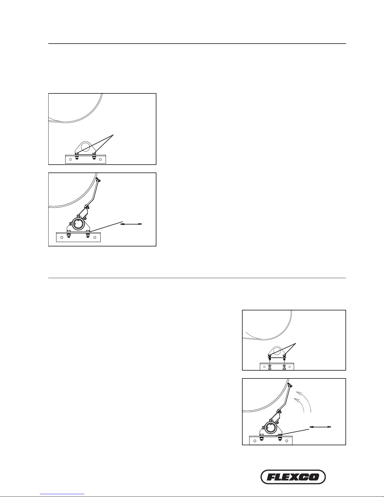
1. Find X and Y measurements. Find the X and Y measurement specifications for the pulley diameter. See charts
on pages 14, 15 and 16. The pulley diameter measurement should include lagging and belt.
Pulley Diameter _________mm; X = _________mm; Y = _________mm
Using the correct X and Y coordinates will position the cleaner at 15° below the horizontal plane on the head
pulley.
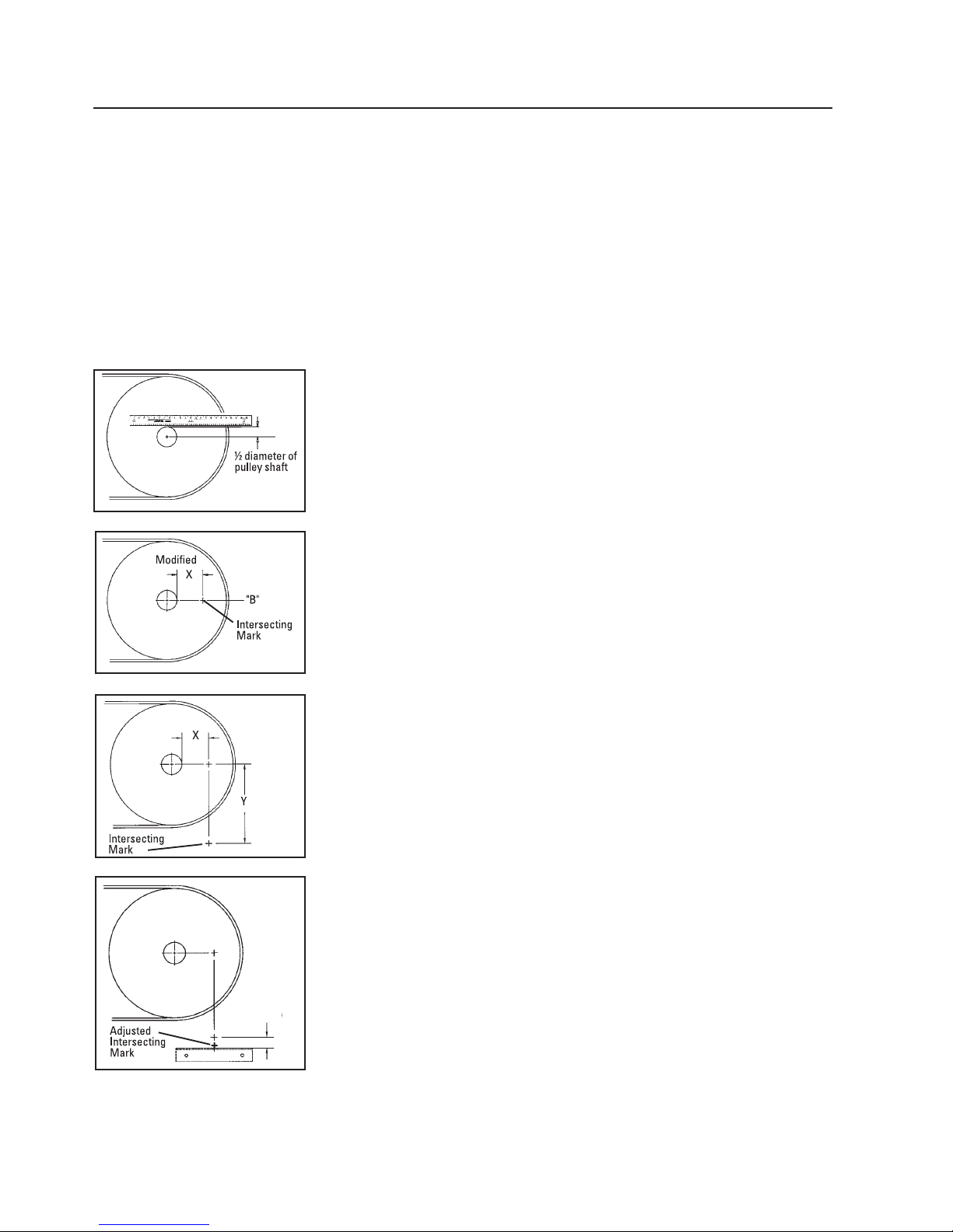
Fig. 1
Fig. 2
Fig. 2b 4. Locate mounting bracket position (horizontal position). To locate the
position of the cleaner mounting bracket, add 70mm to the intersecting
mark (Fig. 2b). This mark indicates the top centre of the mounting bracket.
Fig. 2a
2a. Measure head pulley shaft. Determine the diameter of the pulley shaft
and divide by 2.
2b. Put a level on top of the pulley shaft and draw a horizontal line A.
Measure down from Line A half the diameter of the pulley shaft and draw
Line B parallel from the pulley shaft (Fig. 1).
3a. Mark X dimension. Subtract the above dimension (Step 2a) from the
selected X dimension to establish the modified X dimension. With this
new X dimension measure horizontally from the front of the pulley shaft
forward on Line B and mark on the chute (Fig. 2).
3b. Determine Y dimension. From the horizontal X mark, drop a line
vertically down to the selected Y dimension and draw an intersecting mark
(Fig. 2a). This is the correct position of the centre of the pole.
Chute Mounting
70mm
9
+ +
+
4.2a H-Type©Primary Cleaner with V-Tips
Section 4 – Installation Instructions
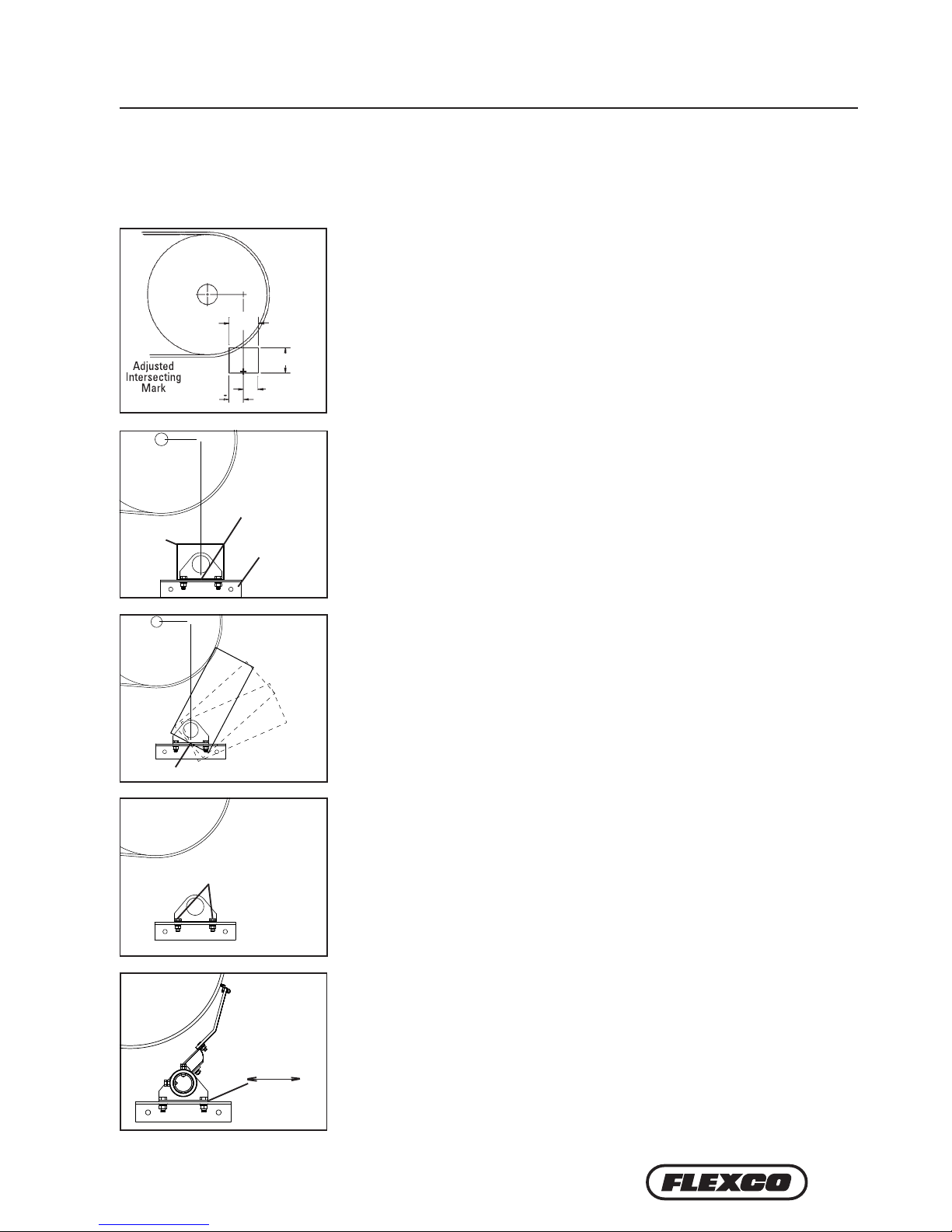
Fig. 3 5. Cut chute opening. Using the adjusted intersecting mark (“+”) established in
Step 4, layout and cut the required opening 125x150mm on the chute (Fig. 3).
If access hole is required, see Step 7.
6. Install the mounting brackets. Centre the mounting bracket on the bottom of
the opening. Bolt or weld in position (Fig 4). Repeat process on opposite side.
7. Cutting the access hole. Cut access hole, centreing the bottom edge on the
adjusted intersecting mark (“+”) established in Step 4. Width of hole should be
175mm; height should be 325mm for extra small arms, 375mm for small arms,
420mm for medium arms, 450mm for large arms or 555mm for extra large
arms. Access hole may be oriented within the range shown (Fig. 5), provided
bottom edge is still centreed as described above.
Slide
Fig. 7 9. Position the pole. Rotate pole upward to bring tips into contact with head
pulley (Fig. 7). Centre the tips across the belt. While applying light pressure
on the centre tip, shi loosened bearing mount until tips are contacting belt
evenly across full width. Lock cleaner into this position by tightening
bearing mount bolts.
For step-by-step instructions on installing the spring tensioner, refer to page 13.
Bearing Mount Bolts
8. Install the pole.Remove the two bearing mount bolts from one of the
bearing mounts (Fig. 6). (If chute mount, remove from the side with access
hole.) Slide the pole across the pulley and into the bearing mount on other
side and allow tips to hang down. Install the removed bearing mount on
the pole and reattach to the mounting bracket. Do not tighten; leave nger
tight.
150mm
125mm
Chute Mounting (cont.)
75mm
75mm
+ +
+
Chute
Opening
Adjusted
intersecting
mark
Mounting
Bracket
Fig. 4
Fig. 5
Adjusted Intersecting Mark
Fig. 6
10 H-Type®Primary Cleaner with V-Tips
4.2b H-Type©Primary Cleaner with V-Tips
Section 4 – Installation Instructions
Fig. 2
Fig. 3
a) shaft to structure ________
b) pulley shaft diameter ________ ÷ 2 ________ +
c) pulley shaft centre line to structure = ________
d) add X measurement from chart ________ +
centre of pole from structure = ________
e) add 175mm (half length of
mounting bracket) 175mm +
length of support material needed = ________
3. Locate X location.
a.) Measure from the back of the pulley shaft to the support structure (Fig. 3).
b.) Pulley shaft diameter divided by 2.
c.) Add dimensions from a) and b). This dimension is the pulley shaft centreline to the support structure.
d.) Add the given X dimension to c). The sum indicates the distance from the centre of the pole to the support
structure.
e.) Add 175mm (half the length of the mounting bracket). The sum is the total length of support material needed
to correctly locate the mounting brackets.
4. Secure mounting support pieces to the support structure.Weld support pieces to the support structure.
75x75mm angle works well for these support pieces.
5. Prepare the support pieces for the cleaner mounting brackets. Clamp the mounting bracket on the support
piece. Mark and drill holes for mounting or weld.
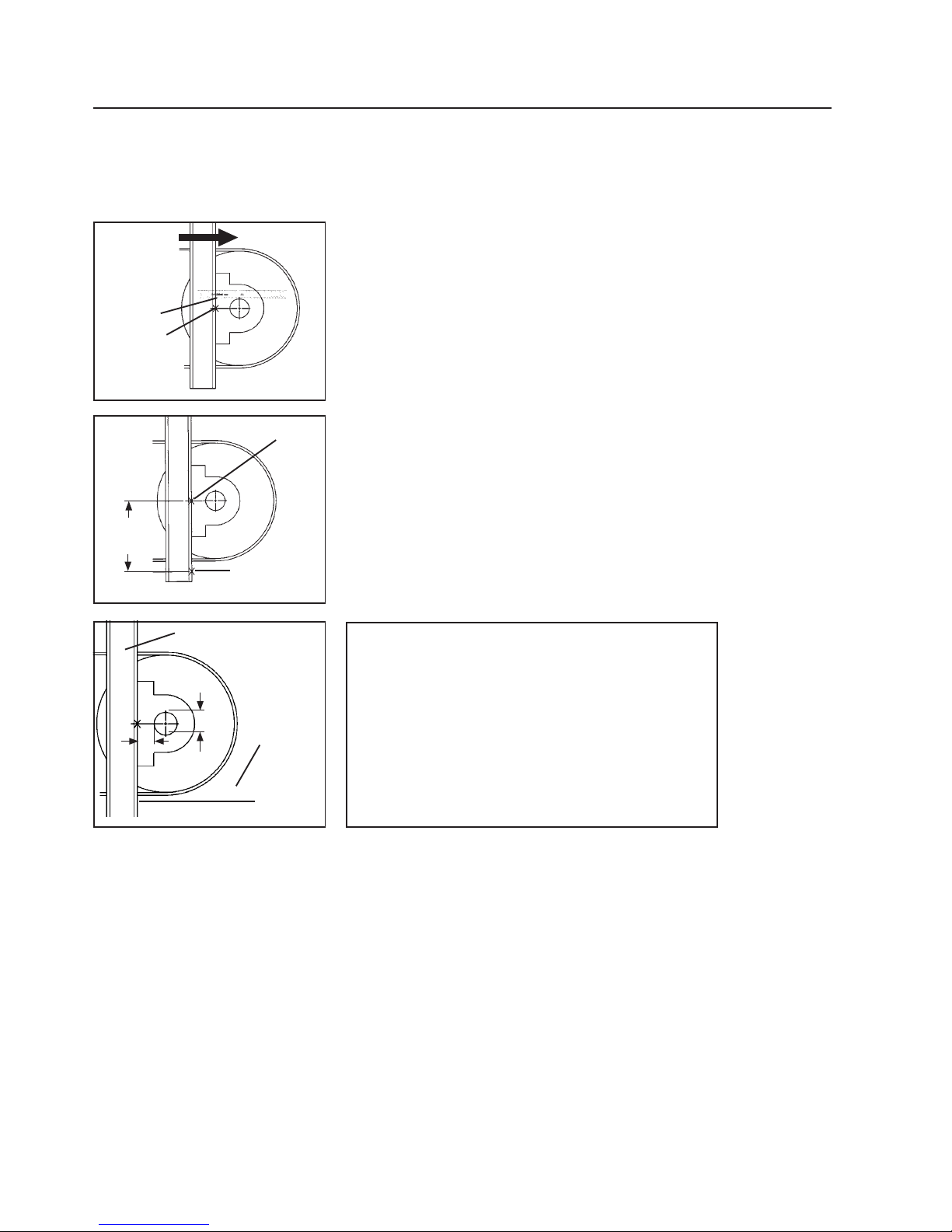
1. Find X and Y measurements. Find the X and Y measurement
specifications for the pulley diameter. See charts on pages 12 and 13.
The pulley diameter measurement should include lagging and belt.
Pulley Diameter________mm X________mm Y________mm
Using the correct X and Y coordinates will position the cleaner at 15°
below the horizontal plane on the head pulley.
2a. Locate Y location. Determine the diameter of the pulley shaft and
divide by 2.
2b. Put a level on top of the pulley shaft and mark A at the structure.
Measure down from Mark A half the diameter of the pulley shaft and
mark B, locating the shaft centreline (Fig. 1).
2c. Measure down the given Y dimension plus 70mm and mark (Fig. 2).
This mark indicates the top location of support material to be added for
installing the cleaner mounting brackets.
Open Head Mounting
Fig. 1
Mark "B"
Mark "A"
Belt Direction
Mark
Mark "B"
Y + 70mm
c+d+e
Length of
support
material
needed
Support structure
b
a
11
4.2b H-Type©Primary Cleaner with V-Tips
Section 4 – Installation Instructions
7. Position the pole. Rotate pole upward to bring tips into contact with
head pulley (Fig. 7). Centre the tips across the belt. While applying
light pressure on the centre tip, shift loosened bearing mount until
tips are contacting belt evenly across full width. Lock cleaner into
this position by tightening bearing mount bolts.
6. Install the pole. Remove the two bearing mount bolts from one of
the bearing mounts (Fig. 6). (If chute mount, remove from the side
with access hole.) Slide the pole across the pulley and into the bearing
mount on other side and allow tips to hang down. Install the removed
bearing mount on the pole and reattach to the mounting bracket.
NOTE: Do not tighten; leave finger tight.
Fig. 7
4.3 H-Type©Primary Cleaner with V-Tips - Bolt Tensioner
Open Head Mounting (cont.)
Bearing
Mount Bolts
Fig. 6
Slide
1. Install the pole. Remove the two bearing block bolts from
one of the bearing blocks (Fig. 1). (If chute mount, remove
from the side with access hole.) Slide the pole across the
pulley and into the bearing block on other side and allow tips
to hang down. Install the removed bearing block on the pole
and reattach to the mounting bracket. Do not tighten; leave
nger tight.
2. Position the pole. Rotate pole upward to bring tips into
contact with head pulley (Fig. 2). Centre the tips across
the belt. While applying light pressure on the centre tip,
shi loosened bearing block until tips are contacting belt
evenly across full width. Lock cleaner into this position by
tightening bearing mount bolts.
Fig. 2
Fig. 1
BEARING
BLOCK
BOLTS
Slide

12 H-Type®Primary Cleaner with V-Tips
Section 4 – Installation Instructions
4.3 H-Type©Primary Cleaner with V-Tips - Bolt Tensioner
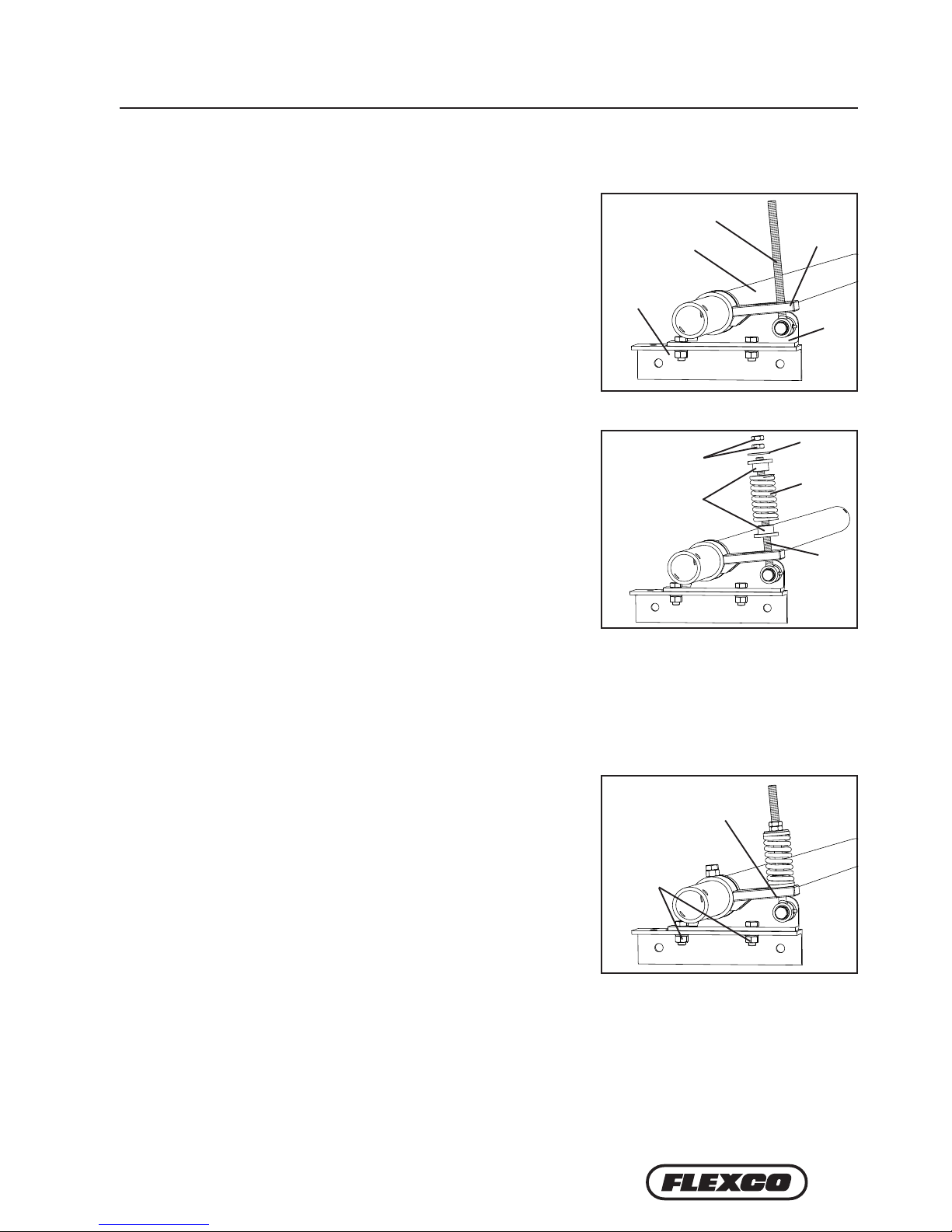
3. Install adjusting arms.
Note: If using optional spring tensioner, go to separate
instructions included in packet.
a. Screw adjusting bolts into the welded nut on each
mounting bracket (about 25mm above the mounting
bracket).
b. With pole rotated up, so that all tips contact the head
pulley, slide the adjusting arm onto pole, tight against
bearing block, resting on the adjusting bolt, pointed away
from the head pulley (Fig. 8). Tighten both adjusting arm
lock bolts and lock nuts (in the order shown in Fig. 3).
Repeat on opposite side.
4. Set tip tension.
Apply the following tension:
V-Tips -- 1-1/2 turns
Lock both adjusting bolt lock nuts (Fig. 4).
Fig. 3
Fig. 4
ADJUSTING ARM
LOCK BOLTS &
LOCK NUTS
ADJUSTING ARM
25mm
ADJUSTING
BOLT & LOCK NUT
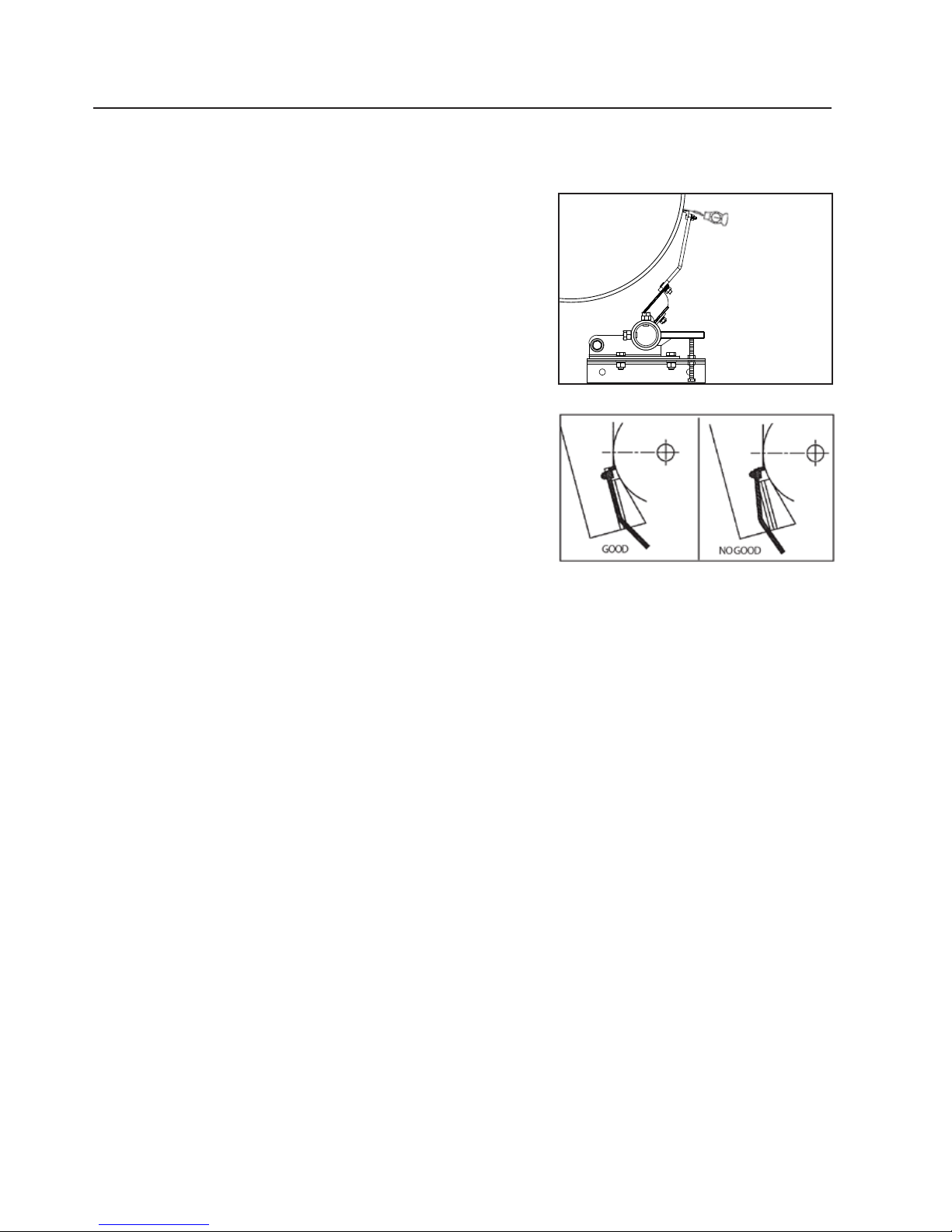
5. Check for correct tip tension. Place a Tip Tension Gauge
between the tip and the belt on the centre tip (or tips) (Fig.
5). While pulling in a straight motion, read the tension
required to break contact between the tip and belt. 8kg is
recommended. Also check tension on both outer tips. Make
tension adjustments if needed.
6. Check tip alignment with gauge provided. Align the gauge
against the head pulley and move down until the gauge
contacts the top of the blade. e suspension arm should
align with lines marked on gauge (Fig. 6). If the alignment
is not correct, loosen both bearing block bolts and slide
pole to gain correct alignment. Correct one side at a time.
Tighten bolts and repeat Step 5.
7. Test run cleaner and inspect operation. If vibration occurs or more cleaning eciency is desired, increase tip
tension by making a 1/2 turn on each adjustment bolt.
Fig. 5
Fig. 6
13
Section 4 – Installation Instructions
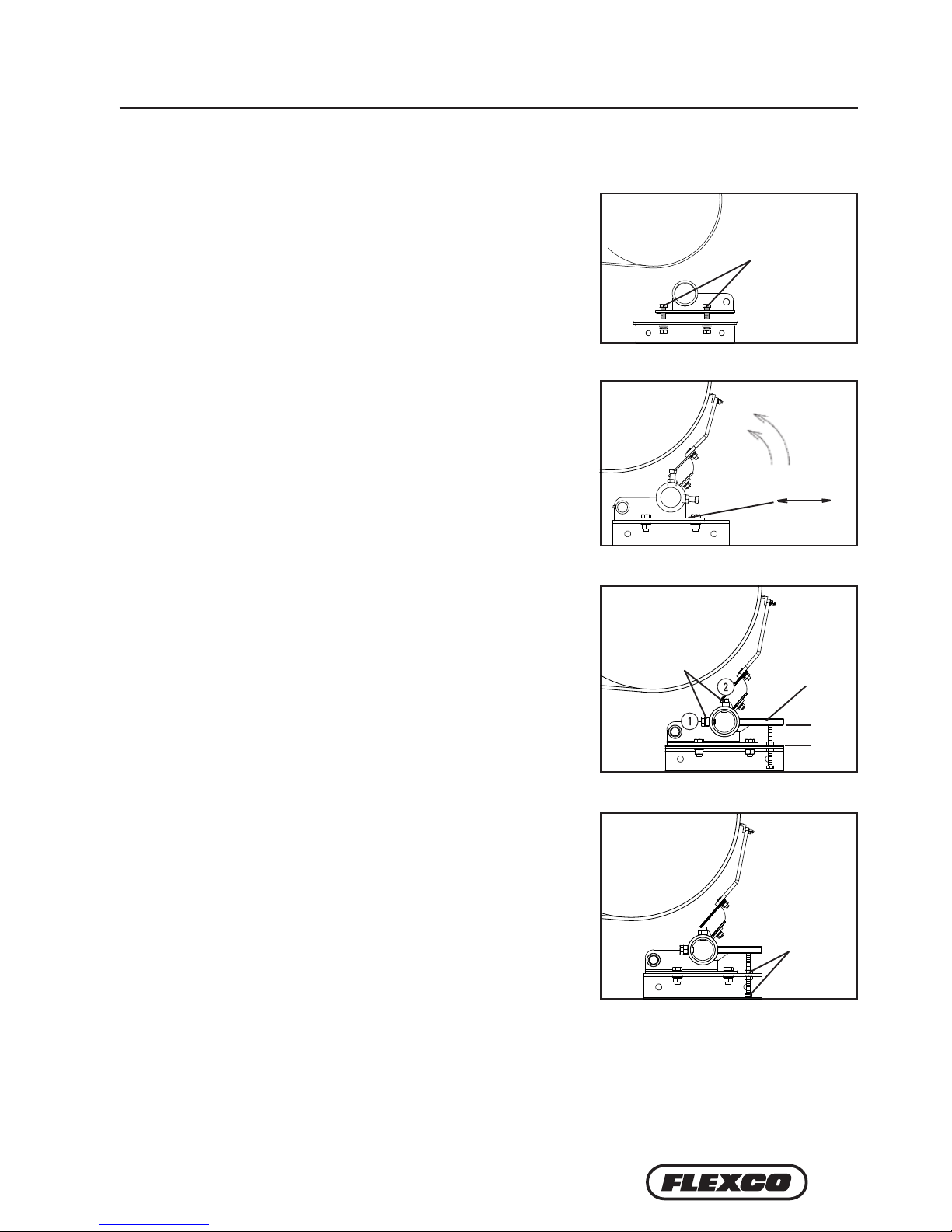
4.4 H-Type©Primary Cleaner with PCST Tensioner
1. Install the compression spring tensioner.
Remove the adjusting
nuts, bushings and spring from the pivot rod. Insert the pivot arm
through the slot in the torque arm. Slide the torque arm onto the
pole end (be sure the rotation of the arm is correct to tension the
blade).
4. Tension the blades to the belt. Rotate the blades until they
contact the belt. While holding the spring bushing flat on the
torque arm, rotate the torque arm until the pivot arm is against
the end of the slot nearest the pole. Tighten the locking bolts
and jam nuts on the torque arm (Fig. 3). NOTE: The torque arm
should be up against the mounting plate.
3. Verify your “C” dimension to insure the pole is in the correct position.
2. Reassemble the spring assembly. Slide the spring, washer and
bushings onto the pivot arm and turn the two adjusting nuts so
about 6mm of the pivot arm is exposed above the nuts (Fig. 2).
Pivot Arm
Torque Arm
Pivot
Shaft
Bracket
Mounting
Plate
Pole
Fig. 1
Fig. 2 Adjusting
Nuts
Washer
Bushings
Spring
Pivot
Arm
Fig. 3
Pivot Arm against slot
end nearest the pole
Tighten
locking
bolts and
jam nuts
14 H-Type®Primary Cleaner with V-Tips
Section 4 – Installation Instructions
4.4 H-Type©Primary Cleaner with PCST Tensioner
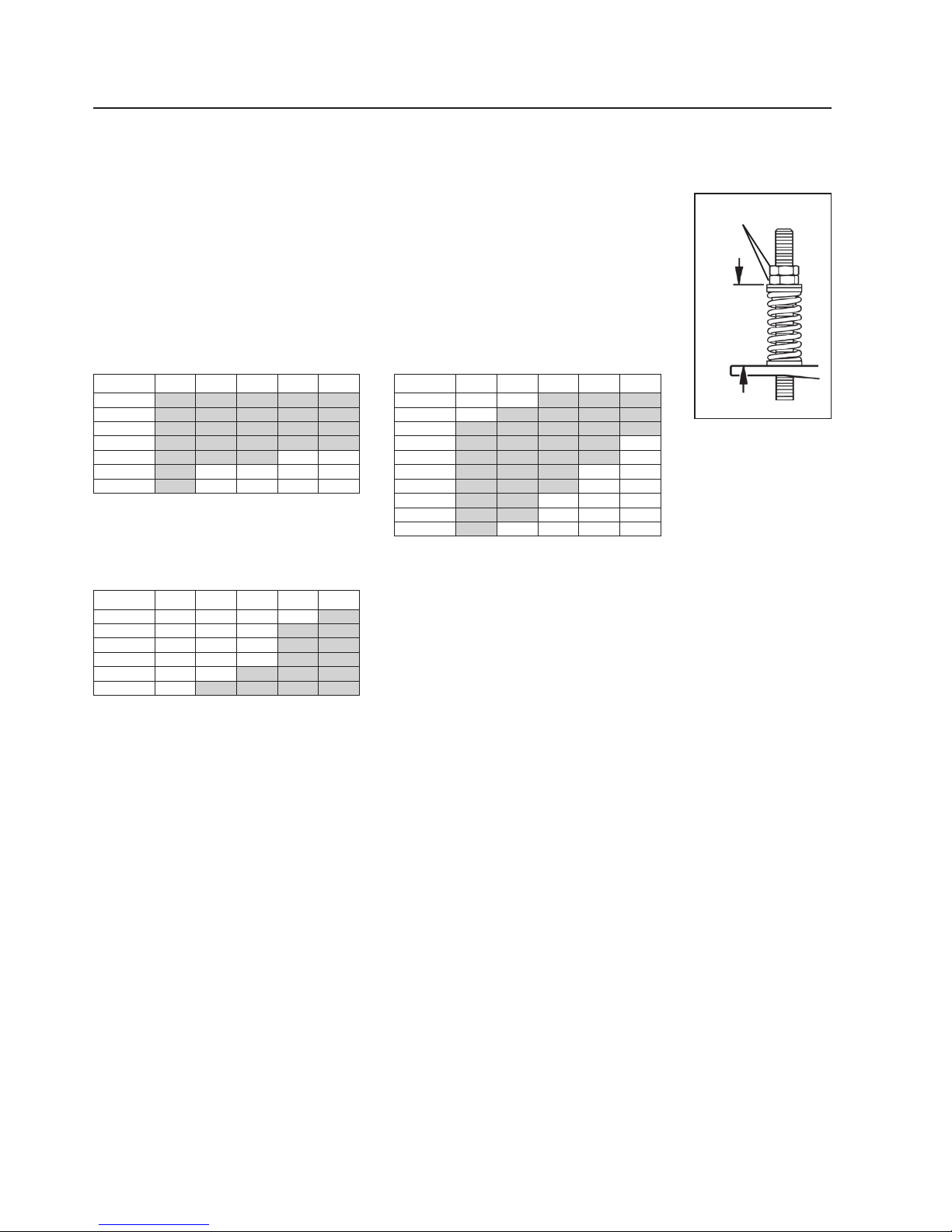
5. Set the correct blade tension. Refer to the charts below for the spring length required
for the belt width. Lightly pull the pivot arm toward the end of the torque arm slot
nearest the pole and turn the adjusting nuts until the required spring length is achieved
(Fig. 4). Lock the top adjusting nut.
Test run the cleaner. Run the conveyor for at least 15 minutes and inspect the cleaning performance. Check the
spring length for proper tensioning. Make adjustments as necessary.
Tighten locking
bolts and jam nuts
Pivot Arm against slot
end nearest the pole
Adjusting Nuts
Pivot Arm
Bushings
Spring
Washer
Top of
washer to
top of torque
arm
Adjusting
Nuts
Fig. 4
HV Black Spring Length Chart
Shaded are recommended
Belt Width SS S M L LL
600 112 111 110 109 107
800 110 109 107 107 104
1000 108 106 105 104 100
1200 106 104 102 101 97
1400 105 102 100 98 93
1600 103 100 97 96 90
1800 101 97 95 93 –
HV Gold Spring Length Chart
Shaded are recommended
Belt Width SS S M L LL
1400 -108 106 106 103
1600 108 106 105 104 100
1800 107 105 103 102 98
2000 106 104 102 100 96
2200 105 102 100 99 94
2400 104 101 99 97 –
2600 102 99 97 95 –
2800 101 98 95 94 –
3000 100 97 94 – –
3200 99 95 92 – –
HV Silver Spring Length Chart
Shaded are recommended
Belt Width SS S M L LL
2200 – – 158 157 154
2400 – 158 157 156 152
2600 – 157 156 155 151
2800 – 156 155 154 150
3000 158 155 154 152 148
3200 157 155 153 151 147
15
Section 4 – Installation Instructions
4.5 H-Type©Primary Cleaner with PCST Tensioner - Bolt Tension
1. Install the pole. Remove the two bearing block bolts from
one of the bearing blocks (Fig. 1). (If chute mount, remove
from the side with access hole.) Slide the pole across the
pulley and into the bearing block on other side and allow tips
to hang down. Install the removed bearing block on the pole
and reattach to the mounting bracket. Do not tighten; leave
nger tight.
2. Position the pole. Rotate pole upward to bring tips into
contact with head pulley (Fig. 2). Centre the tips across
the belt. While applying light pressure on the centre tip,
shi loosened bearing block until tips are contacting belt
evenly across full width. Lock cleaner into this position by
tightening bearing mount bolts.
3. Install adjusting arms.
a. Screw adjusting bolts into the threaded mounting bracket
(about 25mm above the mounting bracket).
b. With pole rotated up, so that all tips contact the head
pulley, slide the adjusting arm onto pole, tight against
bearing block, resting on the adjusting bolt, pointed away
from the head pulley (Fig. 8). Tighten both adjusting arm
lock bolts and lock nuts (in the order shown in Fig. 3).
Repeat on opposite side.
4. Set tip tension.
Apply the following tension:
V-Tips — 1-1/2 turns
Lock both adjusting bolt lock nuts (Fig. 4).
Fig. 2
Fig. 3
Fig. 1
Slide
ADJUSTING ARM
LOCK BOLTS &
LOCK NUTS ADJUSTING
ARM
BEARING
BLOCK
BOLTS
25mm
Fig. 4
ADJUSTING
BOLT &
LOCK NUT
16 H-Type®Primary Cleaner with V-Tips
Section 4 – Installation Instructions
4.5 H-Type©Primary Cleaner with PCST Tensioner - Bolt Tension
5. Check for correct tip tension. Place a Tip Tension Gauge
between the tip and the belt on the centre tip (or tips) (Fig.
5). While pulling in a straight motion, read the tension
required to break contact between the tip and belt. 12kg is
recommended. Also check tension on both outer tips. Make
tension adjustments if needed.
6. Check tip alignment with gauge provided. Align the gauge
against the head pulley and move down until the gauge
contacts the top of the blade. e suspension arm should
align with lines marked on gauge (Fig. 6). If the alignment
is not correct, loosen both bearing block bolts and slide
pole to gain correct alignment. Correct one side at a time.
Tighten bolts and repeat Step 5.
7. Test run cleaner and inspect operation. If vibration occurs or more cleaning eciency is desired, increase tip
tension by making a 1/2 turn on each adjustment bolt.
Fig. 5
Fig. 6

17
Section 5 – Cleaner Pole Location Charts
STEMSTEM
STEMSTEM
STEM
STEMSTEM
STEMSTEM
STEM
STEMSTEM
STEMSTEM
STEM
5.1 Pole Location Charts
Extra Small (SS) V-Arms
for Head Pulley Diameters
up to 499mm
Diameter
(Over Belt)
X Y C Gap
250 28 292 294 56
275 40 295 298 51
300 52 299 303 46
325 64 302 309 43
350 76 305 315 39
375 88 308 321 36
400 100 312 327 33
425 113 315 334 30
450 125 318 342 28
475 137 321 349 25
500 149 325 357 23
525 161 328 365 22
550 173 331 373 20
575 185 334 382 18
Small (S) V-Arms
for Head Pulley Diameters
500-799mm
Diameter
(Over Belt) X Y C Gap
350 50 361 365 78
375 62 365 370 73
400 74 368 375 68
425 86 371 381 64
450 98 374 387 60
475 110 377 393 56
500 122 381 400 52
525 134 384 407 49
550 146 387 414 46
575 158 390 421 43
600 171 394 429 40
625 183 397 437 38
650 195 400 445 36
675 207 403 453 33
700 219 407 462 31
725 231 410 470 29
750 243 413 479 27
775 255 416 488 26
800 267 420 497 24
825 279 423 507 23
850 291 426 516 21
875 303 429 526 20
900 315 432 535 18

18 H-Type®Primary Cleaner with V-Tips
Section 5 – Cleaner Pole Location Charts
STEMSTEM
STEMSTEM
STEM
Medium (M) V-Arms
for Head Pulley Diameters
800-999mm
Diameter
(Over Belt) X Y C Gap
650 180 445 480 63
675 192 449 488 60
700 204 452 496 57
725 216 455 504 54
750 228 458 512 54
775 240 462 520 50
800 252 465 529 47
825 264 468 538 45
850 277 471 546 43
875 289 475 555 41
900 301 478 565 39
925 313 481 574 37
950 325 484 583 36
975 337 487 593 34
1000 349 491 602 32
1025 361 494 612 31
1050 373 497 622 29
1075 385 500 632 28
1100 397 504 641 27
1125 409 507 652 26
5.1 Pole Location Charts (cont.)
Large (L) V-Arms
for Head Pulley Diameters
1000-1199mm
Diameter
(Over Belt) X Y C Gap
850 253 494 556 46
875 265 498 564 43
900 278 501 573 41
925 290 504 581 39
950 302 507 590 37
975 314 511 599 35
1000 326 514 608 33
1025 338 517 618 31
1050 350 520 627 29
1075 362 524 637 27
1100 374 527 646 26
1125 386 530 656 24
1150 398 533 666 22
1175 410 537 675 21
1200 422 540 685 20
STEMSTEM
STEMSTEM
STEM
STEMSTEM
STEMSTEM
STEM
STEMSTEM
STEMSTEM
STEM

19
Section 5 – Cleaner Pole Location Charts
5.1 Pole Location Charts (cont.)
Extra Large (XL) V-Arms
for Head Pulley Diameters
1200-1700mm
Diameter
(Over Belt) X Y C Gap
1200 414 650 771 79
1225 426 653 780 76
1250 438 657 789 74
1275 450 660 799 72
1300 462 663 808 70
1325 474 666 818 68
1350 486 670 827 66
1375 498 673 837 64
1400 510 676 847 62
1425 522 679 857 60
1450 534 683 867 59
1475 546 686 877 57
1500 558 689 887 55
1525 570 692 897 54
1550 583 695 907 52
1575 595 699 917 51
1600 607 702 928 49
1625 619 705 938 48
1650 631 708 949 47
1675 643 712 959 45
1700 655 715 970 44
STEMSTEM
STEMSTEM
STEM
STEMSTEM
STEMSTEM
STEM

20 H-Type®Primary Cleaner with V-Tips
• Recheck that all fasteners are tightened properly.
• Add pole caps.
• Apply all supplied labels to the cleaner .
• Check the blade location on the belt.
• Be sure that all installation materials and tools have been removed from the belt and the conveyor area.
6.2 Test Run the Conveyor
• Run the conveyor for at least 15 minutes and inspect the cleaning performance.
• Check the tensioner spring for recommended length (proper tensioning).
• Make adjustments as necessary.
NOTE: Observing the cleaner when it is running and performing properly will help to detect problems or
when adjustments are needed later.
6.1 Pre-Op Checklist
Section 6 – Pre-Operation Checklist and Testing
This manual suits for next models
2
Table of contents
Other Flexco Ultrasonic Jewelry Cleaner manuals


Popular Ultrasonic Jewelry Cleaner manuals by other brands


DURASONIC
DURASONIC DS3L user manual

HIKOKI
HIKOKI R 18DTB Handling instructions

Makita
Makita CL070D Series instruction manual

Sorceressita
Sorceressita Food Ingredient Cleaner operation instruction

Sauber
Sauber FC-123454.4 Instructions for use

Audiodesksysteme Glass
Audiodesksysteme Glass Vinyl Cleaner PRO operating instructions