&)(*,', Read carefully the installation, operating and maintenance instructions manual (“Manual”) to avoid serious personal injury and/or
property damage and to ensure safe use and proper care of this Product.
**',0 - Warranty is extended to all purchasers of the new product. The warranty is non-transferable. Flexcon warrants to the purchaser or first
user of the new Product that at the time of manufacture, the Product is free from defect in material or workmanship for five (5) years from the date
of manufacture. Any warranty claim must be made within five (5) years (unless another time period is set forth in the Manual), measured from the
date of manufacture.
In the event of a breach of the foregoing warranty and upon proper and timely notification to Flexcon, Flexcon will at its option either: make
repairs to correct any defect in material or workmanship, or supply and ship either new or used replacement parts or products. Flexcon will not
accept any claims for, nor will Flexcon be responsible for, any other costs including labor.
/%-+$('+ - This warranty does not cover any failure or problem unless it was caused by a defect in material or workmanship. In addition, this
warranty shall not apply:
1If the Product is not correctly installed, operated, repaired or maintained as described in the Manual provided with the Product.
1To any failure or malfunction resulting from (i) misuse or abuse, (ii) improper or negligent handling, shipping (by anyone other than Flexcon),
storage, use or operation, or (iii) damages to the tank caused by lightning, floods, fire, freezing or any other environmental condition.
1To damages caused by any unauthorized alteration to the Product, or any attempt to repair tank leaks or parts.
1To any failure or problem resulting from the use of the Product for any purpose other than those specified in the Manual.
1If the Product is used anywhere except the United States, its territories or possessions, or Canada.
1To labor costs, shipping charges, service charges, delivery expenses, administrative fees or any costs incurred in removing or reinstalling the Products.
1To any claims submitted to Flexcon or a Flexcon authorized distributor or dealer more than 30 days after expiration of the applicable warranty time
period described in this Warranty;
1To any repair or replacement costs not authorized in advance by Flexcon.
**',0 $&$,,$('+ - All implied warranties including the implied warranties of merchantability and fitness for a particular purpose are
specifically disclaimed.
$&$,,$('+("!&! $!+ - The remedies contained in this warranty are the purchaser’s or first user’s exclusive remedies. In no circumstances
will Flexcon be liable for more than, and purchaser-first user’s remedies shall not exceed, the price paid for the Product. In no case shall Flexcon
be liable for any special, indirect, incidental or consequential damages, whether resulting from non-delivery or from the use, misuse, or inability to
use the Product or from defects in the product or from Flexcon’s own negligence or other tort. These exclusions apply regardless of whether such
damages are sought for breach of warranty, breach of contract, negligence, strict liability, in tort or under any other legal theory. Excluded damages
include, but are not limited to, inconvenience, loss or damage to property, mold, loss of profits, loss of savings or revenue, loss of use of the
Products or any associated equipment, facilities, buildings or services, downtime, and the claims of third parties including customers.
#,(("(-.!*(%!&(.!*! 0#$+**',0 – You must notify the authorized Flexcon distributor or dealer who sold you
the Product within 30 days of the event leading to the Warranty claim. Any covered Warranty service must be authorized by the Flexcon distributor
or dealer which sold you the Product. If you do not receive a prompt response, call Flexcon directly at 781.986.2424. otice of a Warranty claim
should be submitted within 60 days of the event leading to the claim by the authorized distributor/dealer to Flexcon at the following address:
Flexcon Industries, Warranty Claim Dept., P.O. Box 782, Randolph, MA 02368
Before Flexcon determines to provide any replacement part or Product, it may, as a pre-condition to making such a determination, require that the
warranty claimant ship the Product, postage prepaid, to an authorized Flexcon distributor, or to Flexcon, and provide proof of purchase evidenced
by the original sales receipt.
!)%!&!',*( -,**',0 - In case of replacement of a Product or any component part, Flexcon reserves the right to make changes in
the design, construction, or material of the substitute components or products, which shall be subject to all of the terms and limitations of this
Warranty, except that the applicable warranty periods shall be reduced by the amount of time the warranty claimant owned the product prior to
submitting notification or the warranty claim.
Owners Record Keep for later use
Serial number (see tank data label at bottom of tank): __________________________________________________________________________
Model (see tank data label at bottom of tank): _______________________________________________________________________________
Date Installed: _________________________________________________________________________________________________________
Installer ame: _________________________________________________________________________________________________________
Telephone number: ____________________________________________________________________________________________________
Retain copy of cancelled check and installation receipt
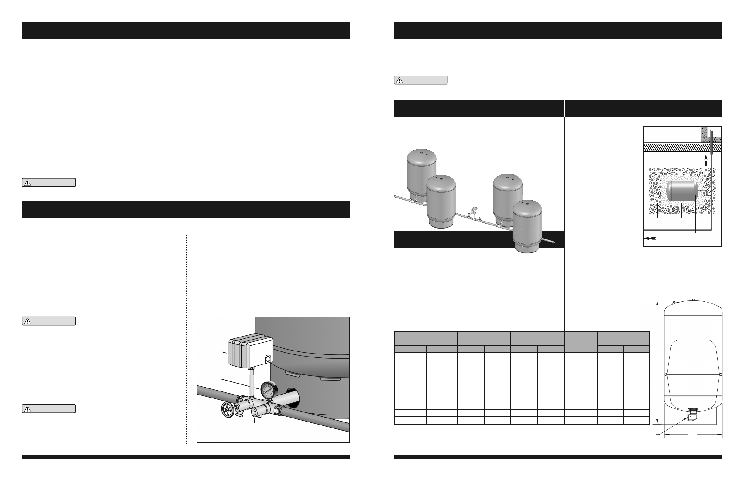
This well tank has been designed to store and deliver
water under pressure between pump cycles in a domestic
water system. It features a patented Controlled Action
Diaphragm (CAD2) system that completely contains the
system water in a safe SF approved chamber. The CAD2
system prevents water from ever touching the internal
walls of the tank which greatly reduces external conden-
sation. Each tank is finished with a two coat appliance
quality paint finish to minimize external corrosion.
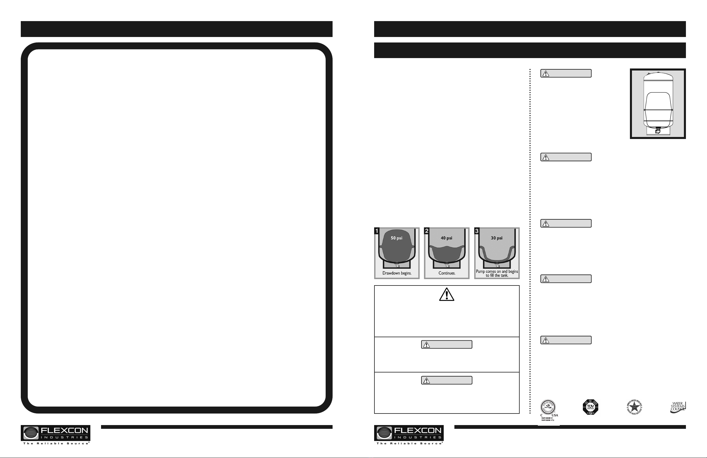
Without a storage tank, a domestic water system’s pump
would cycle (turn on) every time there was a demand for
water. This frequent and potentially short cycling would
shorten the useful life of the pump. Flexcon well tanks are
designed to store water when the pump is running and
then deliver pressurized water back to the system when the
pump is shut off. A properly sized well tank will store at least
one gallon of water for every gallon per minute (GPM) of
pump capacity. This allows for fewer pump starts and longer
run times which should maximize the life of the pump.
""
""
# " "
! "
"
"#
!
"
"#
! "
"
"
This product
must be in-
stalled by a 8$/,),('52)(66,21$/ fol-
lowing all local and national plumbing and
electrical codes. Read and understand
fully the instructions included here and
those on the Flexcon website which are
updated on a regular basis. This product
must be inspected annually by a qualified
professional for any signs of corrosion or
leakage and replaced immediately if these
signs are present. Failure to follow these
instructions may result in serious injury or
death and or property damage and will void the product warranty.
Explosion Hazard This well tank is
designed for water storage at a maximum
pressure of 125 psi and a maximum temperature of 140 F. A properly
sized pressure relief valve set at a maximum of 100 psi must be installed
in the system. This tank is shipped with a pre-charge of 38 psi and any
adjustment to the pre-charge must be done prior to installation and at
ambient temperature. Do not adjust the pre-charge of this tank if the
product is corroded or damaged or shows any signs of diminished
integrity. The maximum allowable pre-charge in this expansion tank is
80 psi. Failure to follow these instructions is U SAFE and may result in
serious injury or death and or property damage.
This well tank and the associated piping may
in time leak. This tank must be installed in a
location where water leakage will not cause property damage and there
must be means for adequate drainage. This tank must not be installed in
a location that is subject to freezing. This tank must be installed in the
vertical position. The manufacturer of this product is not liable or
responsible for any water damage associated with the installation and or
failure of this product. Failure to follow these instructions may result in
personal injury or property damage.
This tank is intended for use on potable
water systems only and any other use may
be dangerous and will void the warranty. This products performance and
lifespan can be significantly impacted by aggressive water conditions.
A water test should be conducted specifically looking for corrosive water,
acids and other relevant water contaminants which if present must be
treated appropriately. The system piping must be properly grounded to
earth. A dielectric union may be required in the system. Failure to
follow these instructions may result in serious injury or death and or
property damage.
C a li Fo rn i a p r o po s i T io n 6 5
WarninG! This product contains a chem-
ical known by the State of California to cause cancer and birth defects or
other reproductive harm. (California installer-California law requires that
this notice be given to the consumer/end user of this product.) For more
information, contact the manufacturer at www.flexconind.com.
These instructions and warnings are subject to periodic updates on the
Flexcon website :::)/(;&21,1'&20 and should be regularly reviewed
by the consumer for important safety and instruction updates.
6200003C
300 Pond S ree , Randolph, Massachuse s 02368, Call 1.781.986.2424, Fax 1.781.986.2029, www.flexconind.com © 2014 Rev. 1.23 300 Pond S ree , Randolph, Massachuse s 02368, Call 1.781.986.2424, Fax 1.781.986.2029, www.flexconind.com © 2014 Rev. 1.23


 Operation and maintenance instructions")