FlexGain FOM16 Owner's manual

F
FO
OM
M1
16
6
T
TM
M
I
In
ns
st
ta
al
ll
la
at
ti
io
on
n
a
an
nd
d
O
Op
pe
er
ra
at
ti
io
on
n
VER :2.0


FOM16 Installation Description
FOM16-V2.0-20021114
-i-
FOM16 Installation Description
Table of Contents
1. PREVIOUS PREPARATION..................................................................................................................................... 1
2. MECHANICAL INSTALLATION ............................................................................................................................ 2
3. ELECTRICAL INSTALLATION.............................................................................................................................. 4
4. OPTICAL INSTALLATION ...................................................................................................................................... 7
5. FRONT PANEL INDICATOR ................................................................................................................................... 7
6. FRONT PANEL OPERATION ................................................................................................................................ 10
6.1 MENU MAPPING TREE ........................................................................................................................................... 11
6.2 CONFIGURE MENU................................................................................................................................................. 12
6.2.1 Line Service Setting Menu ............................................................................................................................ 12
6.2.3 Line Equalizer Setting Menu( T1 TYPE ONLY)............................................................................................ 15
6.2.4 Address Setting Menu.................................................................................................................................... 16
6.2.5 Reset Menu.................................................................................................................................................... 17
6.2.6 Loopback Setting Menu ................................................................................................................................ 17
6.2.7 Release Loopback Setting Menu ................................................................................................................... 18
6.2.8 Protection Switch Menu................................................................................................................................ 19
6.3 STATUS MENU ....................................................................................................................................................... 20
6.3.1 Line Service Status Menu.............................................................................................................................. 20
6.3.2 Line Coding Status Menu.............................................................................................................................. 22
6.3.3 Line Equalizer Status Menu .......................................................................................................................... 22
6.3.4 Address Status Menu ..................................................................................................................................... 23
6.3.5 Version Status Menu...................................................................................................................................... 24
6.3.6 Equipment Status Menu ................................................................................................................................ 24
6.4 ALARM MENU ....................................................................................................................................................... 25
6.4.1 Get current alarm Menu ............................................................................................................................... 25
6.4.2 Get History alarm Menu ............................................................................................................................... 26
6.4.3 Clear history alarm Menu............................................................................................................................. 27
6.5 PERFORMANCE MENU ........................................................................................................................................... 27
6.5.1 Get current 15 minutes PM Menu................................................................................................................. 28
6.5.2 Get current 1 day, 1hour PM Menu .............................................................................................................. 28
6.5.3 Get previous 15 minutes PM Menu............................................................................................................... 29
6.5.4 Get previous 1 day PM Menu ....................................................................................................................... 29
6.5.5 Clear current 15 minutes PM Menu.............................................................................................................. 30
6.5.6 Clear current 1 hour, 1 day PM Menu .......................................................................................................... 30
6.5.7 Clear previous 15 minutes PM Menu............................................................................................................ 31
6.5.8 Clear previous 1 day PM Menu .................................................................................................................... 31
6.5.9 Clear all PM Menu ....................................................................................................................................... 32
6.6 TEST UTILITY MENU.............................................................................................................................................. 32
6.7.1Test LED ........................................................................................................................................................ 32
7. MANAGEMENT OPTIONS.................................................................................................................................... 34
7.1 INTRODUCTION ...................................................................................................................................................... 34
7.2. GRAPHICAL USER INTERFACE............................................................................................................................. 34
8. TROUBLESHOOTING AND DIAGNOSTICS...................................................................................................... 42
8.1 DIAGNOSTICS TESTS .............................................................................................................................................. 42
8.2 TROUBLESHOOTING............................................................................................................................................... 45


FOM16 Installation Description
FOM16-V2.0-20021114
-1-
1. Previous Preparation
1.1 Tools and Materials
Ground Strip
Wire cutters
Multi-meter
Power cable (AWG 8, Single-bone): Red and black both
Ground cable (AWG 14, Single-bone): Green
FC/PC Patch cord: FC/PC connectors, 1310mm single mode fiber
FOM16TM Console Port Installation Dsik#1 and Dsik#2
1.2 Please wear Ground strip during installations to avoid the static electricity.
FOM16 Installation Description
FOM16-V2.0-20021114
-2-
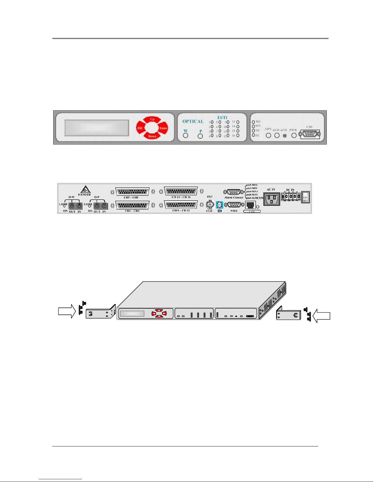
2. Mechanical Installation
2.1 FOM16 is a standard 1 RU unit, which can be mounted on 19 or 23-inch rack. It also works as
a desktop unit. The front view and the rear view are shown in Fig.1 and Fig.2, respectively.
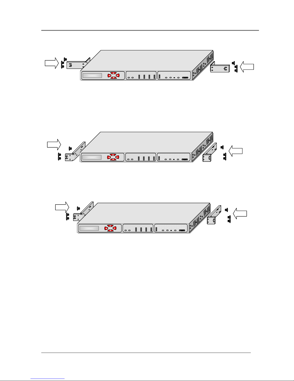
2.2 In order to fit for different size of racks, the brackets can be fastened by means of screws to the
two side walls of the case, as shown in Fig. 3.
2.3 After attaching the brackets, FOM16 is ready for installation in the rack. Fasten the brackets to
the side rails of the rack by means of four screws, two on each side.
Fig. 1 FOM16 Front View
Fig.2 FOM16 Rear View
Fig.3 23-inch rack mountable (I)
FOM16 Installation Description
FOM16-V2.0-20021114
-3-
Fig.5 19-inch rack mountable (I)
Fig.6 19-inch rack mountable (II)
Fig.4 23-inch rack mountable (II)
FOM16 Installation Description
FOM16-V2.0-20021114
-4-
3. Electrical Installation
3.1 FOM16 can be either AC- or DC-powered. If both AC and DC are fed at the time, The AC
power is selectable internally first and the DC power is used as a back up power source.
3.2 Use the rear left AC power connector to connect to an AC power outlet capable of furnishing a
supply voltage for either 110 or 220 VAC.
3.3 Use the rear right DC power connector to connect to a DC power source capable of furnishing
a supply voltage -48 VDC.
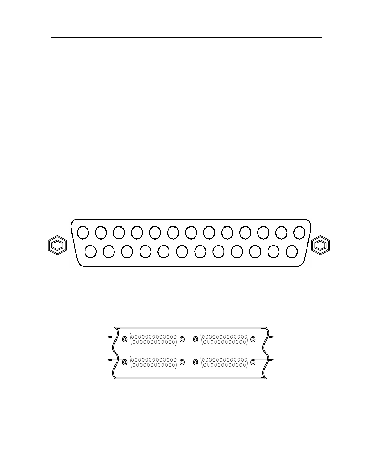
3.4 FOM16 consists of 16 E1 tributaries, i.e. CH1 ~ CH16. Each E1 tributary uses 4 pins, i.e.
Input Tip/Ring and Output Tip/Ring. Each rear DB-25 connector contains a 4-E1-tributary
group, that is, there are 16 pins designated for 4 E1 tributaries and 9 pins for frame ground
(FGND). The pin assignments are shown in the Fig.7 and Fig.8.
3.5 For the unbalance interface, each E1 tributary has two BNC connectors designated TXTIP
(transmit output) and RXTIP (receive input), as shown in Fig.9 and Fig.10.
Fig.8 DB-25 connectors and 16 E1 tributaries
GROUP A CH1~CH4 ÆCH1 ~ CH4
GROUP B CH1~CH4 ÆCH5 ~ CH8
CH1 ~ CH4
CH5 ~ CH8
CH9 ~ CH12
CH13 ~ CH16
GROUP A
GROUP B GROUP D
GROUP C
GROUP C CH1~CH4 ÆCH9 ~ CH12
GROUP D CH1~CH4 ÆCH13 ~ CH16
1417 16 151821 20 192225 24 23
43259761013 12 11 8
Output
Ring4
Output
Tip4
Output
Ring3
Output
Tip3
Output
Ring2
Output
Tip2
Output
Ring1
Output
Tip1
Intput
Ring4
Intput
Tip4
Intput
Ring3
Intput
Tip3
Intput
Ring2
Intput
Tip2
Intput
Ring1
Intput
Tip1
FGNDFGNDFGNDFNGD
FGNDFGNDFGNDFNGD
FGND
Fig.7 DB-25 connector and 4 E1 tributaries
1

FOM16 Installation Description
FOM16-V2.0-20021114
-5-
Fig.10 DB-25 connectors and BNC-connector kit
CH1 ~ CH4
CH5 ~ CH8 CH13 ~ CH16
CH9 ~ CH12
Rack rail
BNC-connector kit
FOM16 rear panel
75 Ω
TXTIP1
RXTIP1
TXTIP2
RXTIP2
TXTIP3
RXTIP3
TXTIP4
RXTIP4
GROUP A
75
Ω
TXTIP1
RXTIP1
TXTIP2
RXTIP2
TXTIP3
RXTIP3
TXTIP4
RXTIP4
GROUP D
75 Ω
TXTIP1
RXTIP1
TXTIP2
RXTIP2
TXTIP3
RXTIP3
TXTIP4
RXTIP4
GROUP C
Fig.9 BNC-connector kit
75
Ω
TXTIP1
RXTIP1
TXTIP2
RXTIP2
TXTIP3
RXTIP3
TXTIP4
RXTIP4
GROUP B

FOM16 Installation Description
FOM16-V2.0-20021114
-6-
3.6 FOM16 provides audible and visual alarm contacts that use relays to activate a circuit loop
between each alarm contact point and the common point in case of an alarm. The pin
assignments of the rear female DB-9 connector are shown in Fig.11.
MJV: Visual Major alarm
MJA: Audible Major alarm
MNV: Visual Minor alarm
MNA: Audible Minor alarm
ALMCOM Common Point
3.7 FOM16 is equipped with a rear LAN port that is an RJ-45 connector. This port operates at a
rate of 10 Mbps over an ETHERNET cable. Pin assignment is shown in Fig.12.
Fig.12 LAN port of an RJ-45 connector
LAN
1ÅÆ8
PIN1 – TX+ (transmit positive out)
PIN2 – TX- (transmit negative out)
PIN3 – RX+ (receive positive in)
PIN6 – RX+ (receive negative in)
Alarm Contact
pin5 - MJA
pin9 – MJV
pin4 – MNA
pin8 – MNV
pin3 - ALMCOM
14 35
6
97
8
2
Fig.11 Alarm contact pin assignment

FOM16 Installation Description
FOM16-V2.0-20021114
-7-
4. Optical Installation
4.1 FC/PC connectors are used for optical interfaces. “IN” and “OUT” are used to indicate the
directions of laser beam input and output. ”O-W” means the optical working pair and “O-P” the
optical protection pair. The working pair of near end must be connected with that of far end and
the same for the protection pair.
4.2 Eye damage may be caused by a broken fiber or by an unterminated connector if the
laser beam is viewed directly or with improper optical instruments.
4.3 When planning the routing of fiber optic cables, avoid sharp bends.
5. Front Panel Indicator
Fig.11 shows the front view of the FOM16, and Table 1 lists the functions of the FOM16
controls, connectors, and indicators, located in the FOM16 front panel. The index numbers in
Table 1 correspond to the item numbers in Fig.13.
Fig.13 FOM16 Front View
7 10 11 14 151 18 19 2223 2627 28 29
3 5 6
1213 16 17 20 21 24 25 30 31 324 2 89

FOM16 Installation Description
FOM16-V2.0-20021114
-8-
Table.1 FOM16 Controls, Connectors and Indicators
NO. Controls or Indicators Function Description
1 LCD
display window
Two by twenty (2×20) characters LCD to show menu items.
2 Enter key pad Used to move down the menu tree or enable a selection.
3 ESC key pad Returns the operation to an upper layer menu.
4 Up key pad Shows the other menu item in the same level.
5 Down key pad Shows the other menu item in the same level.
6 Optical Working
indicator
GREEN: when the optical working link interface is in use.
RED: when the optical working link interface reports loss or
out-of –frame of input signal.
YELLOW: when the optical working link interface is installed but
in stand by state.
7 Optical Protection
indicator
Same functions as item 6 for the optical protection link interface.
8 Ch1 indicator
9 Ch2 indicator
10 Ch3 indicator
11 Ch4 indicator
12 Ch5 indicator
13 Ch6 indicator
14 Ch7 indicator
15 Ch8 indicator
16 Ch9 indicator
17 Ch10 indicator
18 Ch11 indicator
19 Ch12 indicator
20 Ch13 indicator
21 Ch14 indicator
22 Ch15 indicator
23 Ch16 indicator
GREEN: when the corresponding tributary interface is in use.
RED: when the corresponding tributary interface reports loss of input
signal.
OFF: when the corresponding tributary interface is out of service.
Blinking GREEN: when the corresponding tributary interface is in
abnormal operation, i.e., local loopback or remote loopback is
activated.

FOM16 Installation Description
FOM16-V2.0-20021114
-9-
Table.1 FOM16 Controls, Connectors and Indicators (Cont’d)
NO. Controls or Indicators Function Description
24 Major alarm indicator ON when any major alarm occurs.
25 Minor alarm indicator ON when any minor alarm occurs.
26 Near End indicator ON when any near end alarm occurs.
27 Far End indicator ON when any far end alarm occurs.
28 Abnormal operation
indicator
ON when FOM16 is in abnormal operation, that is, any of loopbacks
of tributaries and optical links is activated.
29 Alarm-Cut-Off
indicator
ON when any of FOM16 alarm events is occurred and ACO push
button is pushed.
30 Alarm-Cut-Off
push button
Pushed to disable audible and visible alarms connected to the relay
contacts.
31 Power indicator OFF when the power supply is not powered.
ON when the power supply is turned.
32 CID connector Connection to management interface (RS232 / DB9).

FOM16 Installation Description
FOM16-V2.0-20021114
-10-
6. Front Panel Operation
The front panel consists of a two by twenty (2x20) characters LCD display window and four
keypads each labeled with ESC, Enter, Up, Down, as shown in Fig13.
Enter key is used to move down the menu tree or to enable a selection.
Up and Down keys show other menu item in the same level.
ESC key returns the operation to an upper layer menu or to the main menu.
The first line of LCD shows the operation items and selected items are underlines by a “_” in the
first character.
The second line displays a help string.
A “<” or a ”>” represent the menu is a multi-page.
FOM16 Installation Description
FOM16-V2.0-20021114
-11-
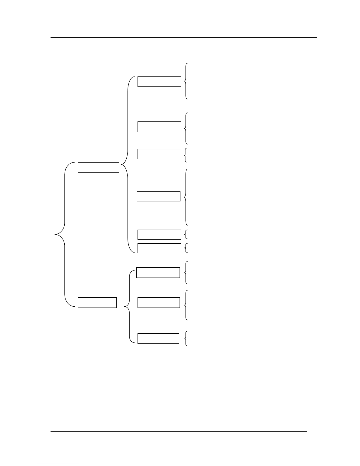
6.1 Menu Mapping Tree
LINESTATUSSETTING
LINECODINGSETTING
LINE EQUALIZER SETTING
ADDRESS SETTING
RESET
LOOPBACKSETTING
LOOPBACKRELEASE
PROTECTIONSWITCH
LINESTATUSMONITOR
LINECODINGMONITOR
LINE EQUALIZER MONITOR
GETADDRESS
GETVERSION
LINEEQUIPMENTMONITOR
CURRENTALARM
HISTORYALARM
CLEARHISTORYALARM
GETCURRENT15MIN
GET CURRENT 1 HOUR
GETCURRENT1DAY
GETPREVIOUS15MIN
GETPREVIOUS1DAY
CLEARCURRENT15MIN
CLEARCURRENT1HOUR
CLEARCURRENT1DAY
CLEARPREVIOUS15MIN
CLEAR PREVIOUS 1 DAY
CLEARALL
LED
DEFAULT SETTING
LINE STATUS SETTING
LINECODINGSETTING
LINE EQUALIZER SETTING
ADDRESS SETTING
RESET
LINESTATUSMONITOR
LINECODINGMONITOR
LINE EQUALIZER MONITOR
GETADDRESS
GETVERSION
LINEEQUIPMENTMONITOR
CURRENTALARM
HISTORYALARM
CLEARHISTORYALARM
LOCAL
CONFIGURE
STATUS
ALARM
PM
TEST
CONFIGURE
REMOTE
ALARM
STATUS
DEFAULT

FOM16 Installation Description
FOM16-V2.0-20021114
-12-
The main menu is shown in Fig.13. It is the first menu display after power up.
Fig.13 Main menu
The first tier menu includes LOCAL and REMOTE. Each sub-menu is further broken down
into sub-level menu. Subsequent chapters give detailed information regarding these menus.
6.2 Configure Menu
The configure group includes SVC, CODE, EQU, ADDRESS, RESET, LPBK, RLSLPBK,
and PROTSW. Use the ◄and the ►keys to cycle through to a proper item and pressing the
Enter key to select the underlined item.
6.2.1 Line Service Setting Menu
PATH: CONFIGUREÆSVCÆLS
1. Use the ◄key and ►key to cycle through to a proper channel and press the Enter key to
elect the module.
2. Use the ◄key and ►key to cycle through to a proper channel and press the Enter key to
select the channel.
LOCAL REMOTE
LOCAL NE
CONFIGURE STATUS >
----TOP----
ALARM PM TEST <
Get Alarm
SVC CODE EQU >
Set-Service
ADDRESSRESET >
Set-Address
SVC CODE EQU
>
LS OPT
Low-Speed
LPBK RLSLPBK PROTSW <
Set-LPBK

FOM16 Installation Description
FOM16-V2.0-20021114
-13-
3. Use ◄and ►key to cycle through to a proper service status and press Enter to select.
4. When completed, the button line shows “ -- -- OK -- -- “ message.
PATH: CONFIGUREÆSVCÆOPT
1. Use the ◄key and ►key to cycle through to a proper channel and press the Enter key to
select the module.
2. Use the ◄key and ►key to cycle through to a proper channel and press the Enter key to
select the channel.
3. Use ◄and ►key to cycle through to a proper service status and press Enter to select.
4. When completed, the button line shows “ -- -- OK -- -- “ message.
IS OOS
In Service
IS OOS
Out Of Service
IS OOS
In Service
IS OOS
Out Of Service
ALL 1 2 3 4 5 6
>
SVC CODE EQU
>
LS OPT
Optical
WORK PROT
Work(Line1)
IS OOS
----OK----
IS OOS
----OK----

FOM16 Installation Description
FOM16-V2.0-20021114
-14-
6.2.2 Line Coding Setting Menu
PATH: CONFIGUREÆCODE
1. Use the ◄key and ►key to cycle through to a proper channel and press the Enter key to
select the module.
2. Use the ◄key and ►key to cycle through to a proper channel and press the Enter key to
select the channel.
3. Use ◄and ►key to cycle through to a proper coding type and press Enter to select.
4. When completed , the bottom line shows “ -- -- OK -- -- “ message.
HDB3(E1)|B8ZS(T1) >
HDB3 | B8ZS Code
AMI <
AMI Code
SVC CODE EQU TYPE >
Set-Code
ALL 1 2 3 4 5 6
>
AMI
-- -- OK -- --

FOM16 Installation Description
FOM16-V2.0-20021114
-15-
6.2.3 Line Equalizer Setting Menu( T1 TYPE ONLY)
PATH: CONFIGUREÆEQU
1. Use the ◄key and ►key to cycle through to a proper channel and press the Enter key to
select the module.
2. Use the ◄key and ►key to cycle through to a proper channel and press the Enter key to
select the channel.
3. Use ◄and ►key to cycle through to a proper equalization type and press Enter to select.
4. When completed , the bottom line shows “ -- -- OK -- -- “ message.
NOTE: If card type is E1 , it shows message
SVC CODE EQU
>
ALL 1 2 3 4 5 6
>
01 2 3 4
T1 : 0 – 133 ft.
01 2 3 4
----OK----
01 2 3 4
E1 Can’t set EQ!

FOM16 Installation Description
FOM16-V2.0-20021114
-16-
6.2.4 Address Setting Menu
PATH: CONFIGUREÆADDRESS
1. Use the ◄key and ►key to cycle through to a proper channel and press the Enter key to
select the address item.
2. Use the ◄key and ►key to cycle through to a proper channel and press the Enter key to
select the sub-address.
3. Use the ◄key and ►key to cycle through to a proper sub-address and press the Enter key
to select the address number. You can use the ►key to cycle through to a proper one and
press the Enter key.
4. When completed , the bottom line shows “ -- -- OK -- -- “ message.
5. Press Esc to escape the above state and back to the state below.Press the ►key to select
XXX and repeat the step 2 through 4 to set subaddress XXX.
6. Use the same procedure to set YYY, ZZZ.
7. You may follow the steps below to make sure the address is set correctly:
Local →Status →Address →IP
8.Note: You have to re-power the FOM16 to enable the address setting.
ADDRESS RESET >
Set-Address
IP GWIP TRIP SUB
IP
WW W X X X >
Www.xxx .yyy.zzz
01 2 3 4 5 6 7 8 9
0
0 1 2 3 4 5 6 7 8 9
----OK----
WW W X X X >
WWW.xxx .yyy.zzz
Table of contents
Other FlexGain Multiplexer manuals


Popular Multiplexer manuals by other brands

Lucent Technologies
Lucent Technologies Multiplexer and Transport System ADM 16/1 Brochure & specs

Vista
Vista Columbus Triplex user manual

Nexperia
Nexperia AN10343 Application note

Alcatel-Lucent
Alcatel-Lucent Data Multiplexer Explore 1665 installation manual

vissonic
vissonic VIS-Quad41 user manual

Pickering
Pickering 40-615A user manual

Paradyne
Paradyne HotWire 8800 DSLAM installation guide

Optical Systems
Optical Systems OSD860 SERIES Operator's manual

Lucent Technologies
Lucent Technologies FiberReach DDM-2000 User & service manual

Sony
Sony BKPF-105A installation manual

Pantron
Pantron IMX-N830 operating instructions

National Instruments
National Instruments NI PXI-2527 Specifications


