FlexGain SA-FOM4 Owner's manual

SA-FOM4TM
(
(F
Fi
ib
be
er
rO
Op
pt
ti
ic
ca
al
lM
Mu
ul
lt
ti
ip
pl
le
ex
xe
er
r)
)
I
In
ns
st
ta
al
ll
la
at
ti
io
on
na
an
nd
dO
Op
pe
er
ra
at
ti
io
on
nD
De
es
sc
cr
ri
ip
pt
ti
io
on
n
V2.0
January 2003


SA-FOM4 Installation Description
SA-FOM4-2.0-20030102
Installation Description
Table of Contents
1. PREVIOUS PREPARATION............................................................................................1
1.1 TOOLS AND MATERIALS..................................................................................................1
2. USER INTERFACE ..............................................................................................................2
2.1 FRONT VIEW AND REAR VIEW ......................................................................................2
2.2 LED DISPLAY STATUS ....................................................................................................2
3. LOOPBACK TESTING.......................................................................................................4
3.1 E1 LOCAL LOOPBACK (E1LLB) ...................................................................................4
3.2 NEAR END (NE) LOCAL LOOPBACK (NELLB).........................................................5
3.3 E1 REMOTE LOOPBACK (E1RLB)................................................................................5
4. DIP SWITCH OPERATION .............................................................................................7
4.1 E1 SERVICE ........................................................................................................................7
4.2 E1 LOCAL LOOPBACK......................................................................................................8
4.3 E1 REMOTE LOOPBACK...................................................................................................8
5. CID CONSOLE OPERATION .........................................................................................9
5.1 CID CONNECTION ............................................................................................................9
5.2 CID MAIN MENU............................................................................................................ 10
5.3 SYSTEM REPORT .............................................................................................................11
5.4 SET E1 CHANNEL TO IN SERVICE ...............................................................................12
5.5 SET E1 CHANNEL TO OUT OF SERVICE.....................................................................13
5.6 SET E1 LOCAL LOOPBACK ...........................................................................................14
5.7 CANCEL E1 LOCAL LOOPBACK ...................................................................................15
5.8 SET E1 NEAR END LOCAL LOOPBACK ......................................................................16
5.9 CANCEL E1 NEAR END LOCAL LOOPBACK..............................................................17
5.10 SET E1 REMOTE LOOPBACK ........................................................................................18
5.11 CANCEL E1 REMOTE LOOPBACK................................................................................20
- i -

SA-FOM4 Installation Description
SA-FOM4-2.0-20030102
6. ELECTRIC POWER AND GROUND INSTALLATIONS ................................21
7. SYSTEM CONNECTIONS ..............................................................................................22
8. ALARM OUTPUT PORT.................................................................................................25
-ii-

SA-FOM4 Installation Description
SA-FOM4-2.0-20030102
1. Previous Preparation
1.1 Tools and Materials
Ground Strip
Wire Cutters
Multi-meter
RJ-45 E1 connector cable
RS232 Connector cable
Power cable (AWG 8, Single-bone): One cable each for red
and black
Ground cable (AWG 14, Single-bone): One green cable
FC/PC Patch cord: FC/PC connectors, 1310mm single
mode fiber
Notice
Please wear ground strip during installations to avoid the
static electricity.
- 1 -
SA-FOM4 Installation Description
SA-FOM4-2.0-20030102
2. User Interface
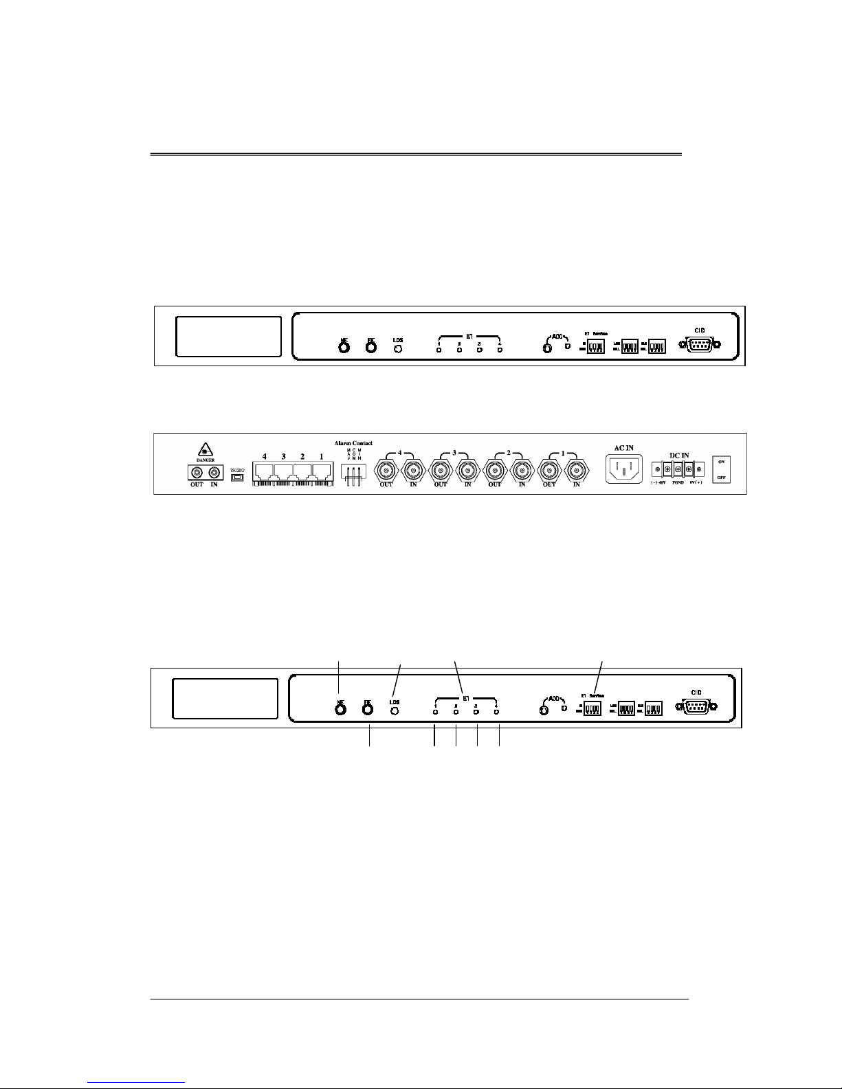
2.1 Front View and Rear View
Figure 1 SA-FOM4 Front View
Figure 2 SA-FOM4 Rear View-w//RJ-45 Connector
2.2 LED Display Status
NE
FE
LOS E1 Tributary
1 23 4
E1 Service
Figure 3 LED Display
NE: Indicates the status of Near End.
Green Light On: Near end system is normal.
Red Light On: Near end optical signal is abnormal
and the buzzer is on.
-2-

SA-FOM4 Installation Description
SA-FOM4-2.0-20030102
Orange Light On: Optical signal is normal, electrical
signal is abnormal and buzzer is on.
FE: Indicates the status of Far End.
Green Light On: Far end system is normal.
Red Light On: Far end optical signal is abnormal
and the buzzer is on.
Orange Light On: Optical signal is normal, electrical
sign is abnormal and buzzer is on.
LOS: Indicates whether the optical interface has lost signal.
No Light On: The optical interface is in normal
status.
Red Light On: The optical interface has lost signal
and buzzer is on.
Red Light Blinking: SA-FOM4 is performing Near End
Local Loopback
E1: There are four E1 tributaries LED – 1, 2, 3 and 4. Each
indicates the status of E1 tributary 1, 2, 3 and 4.
Green Light On: The tributary is in In Service status
and no error occurs.
Red Light On: The tributary is in In Service status
but has lost signal.
Green Light Blinking: The tributary is in Remote
Loopback status.
Red Light Blinking: The tributary is in Local Loopback
status (CID control model only).
Orange Light Blinking: The tributary is receiving loopback
signal from far end.
- 3 -

SA-FOM4 Installation Description
SA-FOM4-2.0-20030102
3. Loopback Testing
This section explains the loopback testing theory. For
operation details, please refer to Unit 4 DIP Switch
Operation or Unit 5 CID Console Operation.
SA-FOM4 is equipped with loopback testing function. This
function enables user to locate the fail point of signal
connection or equipment.
Notice
Please notice that while performing loopback testing,
either local loopback or remote loopback, the
corresponding E1 tributary should be set to Out of Service
(OOS) status.
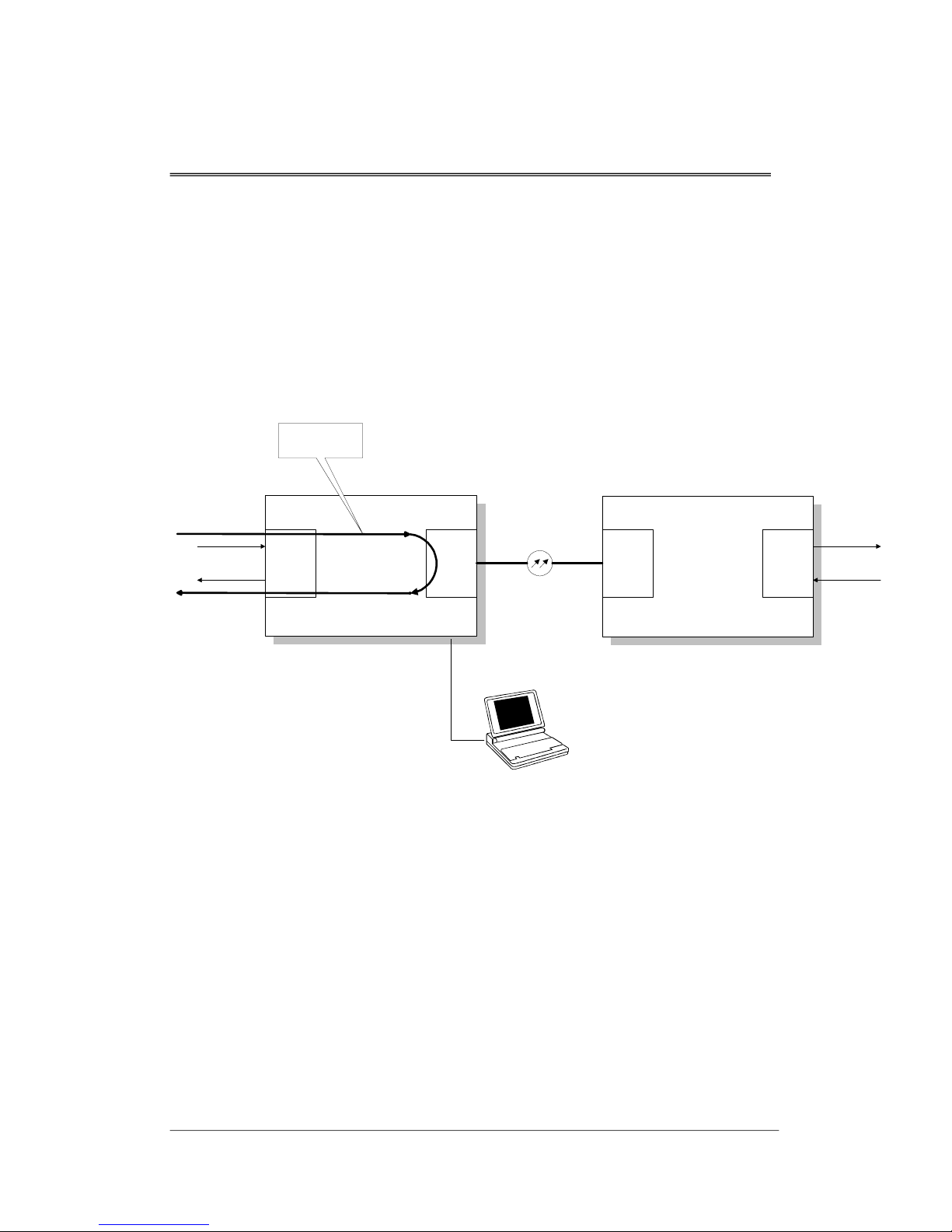
3.1 E1 Local Loopback (E1LLB)
E1 Local Loopback loops the received E1 signal
immediately to the transmit direction at the E1 input for any
E1 channel as shown in the figure listed below.
NEAR END FAR END
4*E1
(EIO)
OPTICAL
(OPT)
4*E1
(EIO)
OPTICAL
(OPT)
E1 LOCAL
LOOPBACK
(T1LLB)
Figure 4 Local Loopback Diagram
-4-
SA-FOM4 Installation Description
SA-FOM4-2.0-20030102
3.2 Near End (NE) Local Loopback (NELLB)
This loopback mode tests the MUX/DEMUX function of
local SA-FOM4. If the transmission quality is as expected,
the electrical session of SA-FOM4 is not the cause of
transmission problem. This function is available on CID
Consol controlled model only.
NEAR END FAR END
4*E1
(EIO)
OPTICAL
(OPT)
4*E1
(EIO)
OPTICAL
(OPT)
NEAR END LOCAL
LOOPBACK
(NELLB)
Figure 5 Near End Local Loopback Diagram
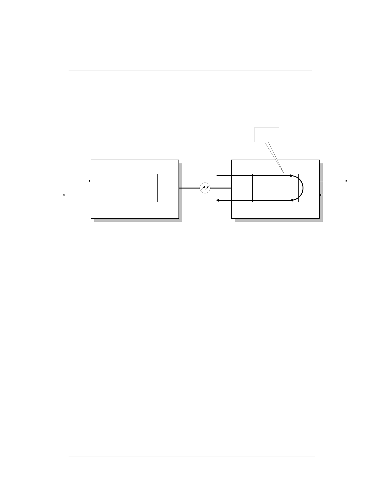
3.3 E1 Remote Loopback (E1RLB)
E1 Remote Loopback function sets remote system to
perform E1 loopback. The signal path is shown as the
following figure.
If the transmission quality is OK after E1RLB is set, the
remote E1 connection or EIO card is the major cause of the
transmission problem.
- 5 -
SA-FOM4 Installation Description
SA-FOM4-2.0-20030102
Note: The E1RLB is set by the local CID. The system will
malfunction if the E1RLB is set by remote system
simultaneously.
NEAR END FAR END
4*E1
(EIO)
OPTICAL
(OPT)
4*E1
(EIO)
OPTICAL
(OPT)
E1 REMOTE
LOOPBACK
(E1RLB)
Figure 6 Remote Loopback Diagram
-6-
SA-FOM4 Installation Description
SA-FOM4-2.0-20030102
4. DIP Switch Operation
This function is available on DIP Switch controlled model
only. Before operation, please make sure the control model
of product purchased. For CID operation, please refer to Unit
5 CID Interface.
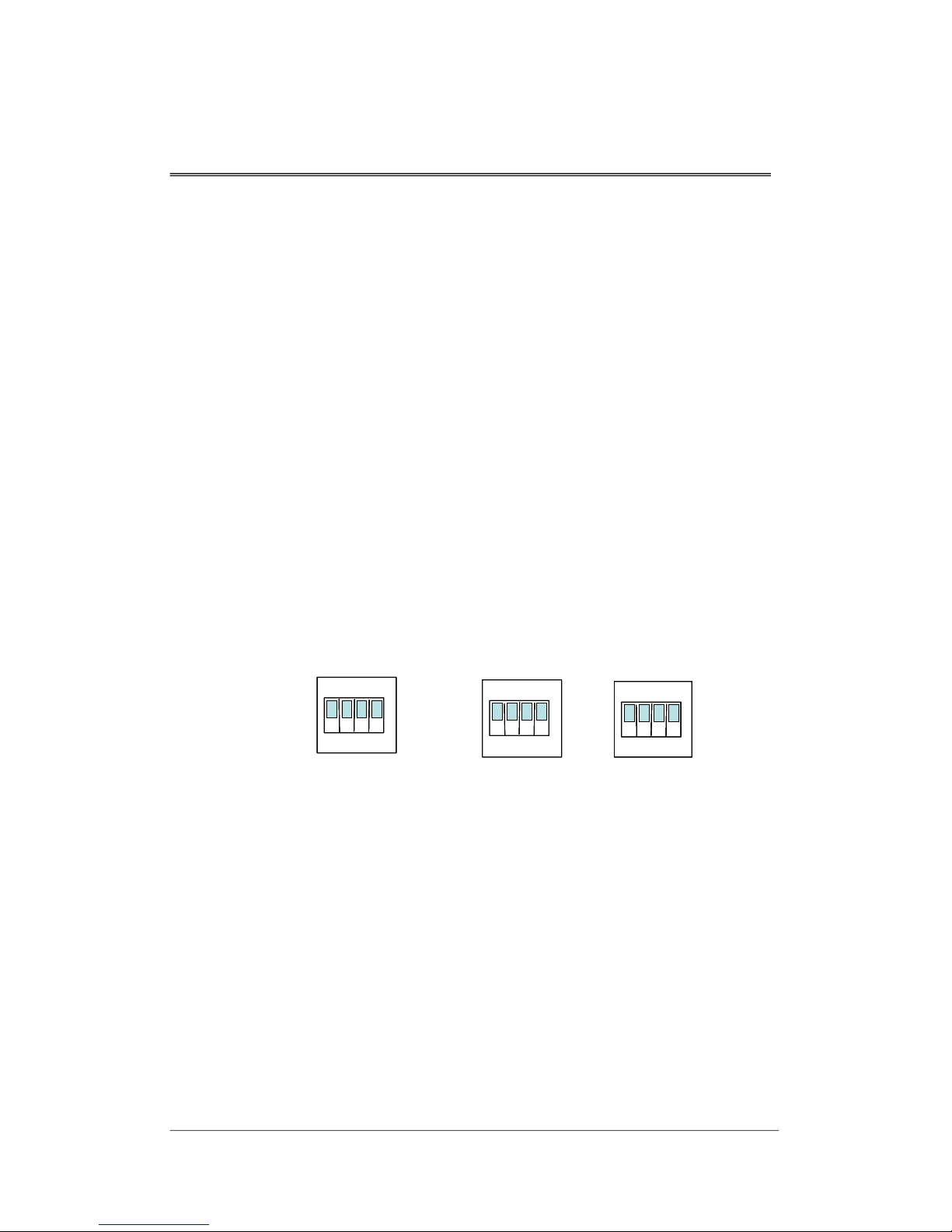
Three DIP switches are presented on SA-FOM4 front panel
(see the following figure).
1. E1 Service: Turn on and off the E1 service. E1 Service
switch is the left switch on Figure 7.
2. Local loopback: Turn on and off the local loopback
function. Locates on the middle of Figure 7.
3. Remote loopback: Turn on and off the remote loopback
function. This is the right switch presented on Figure 7.
E1 ServiceE1 Service
ISISIS
ON
12
3 4
ON
1234
ON
12341234
LLBLLBLLB
ON
1234
ON
1234
ON
12341234
RLBRLBRLB
OOSOOSOOS NLLNLLNLL NRLNRLNRL
ON
1234
ON
1234
ON
1234
ON
1234
Figure 7 DIP Switch Presented in the Front Panel
4.1 E1 Service
Each E1 tributary can be set to In Service (IS) or Out of
Service (OOS) status by switching the E1 Service DIP
switch to IS or OOS.
The numbers 1, 2, 3 and 4 listed on the switch represent E1
tributary 1, 2, 3 and 4.
- 7 -

SA-FOM4 Installation Description
SA-FOM4-2.0-20030102
4.2 E1 Local Loopback
By switching the DIP Switch to LLB or NLL, user can turn
on and off the local loopback function.
LLB The corresponding tributary interface is in
local loopback status.
NLL The corresponding tributary interface is not in
local loopback status.
4.3 E1 Remote Loopback
By switching the DIP Switch to RLB or NRL, user can turn
on and off the remote loopback function.
RLB The corresponding tributary interface is in
remote loopback status.
NLL The corresponding tributary interface is not in
remote loopback status.
-8-

SA-FOM4 Installation Description
SA-FOM4-2.0-20030102
5. CID Console Operation
This function is available on CID console control model only.
Before operation, please make sure the control model of
product purchased. For DIP Switch operation, please refer to
Unit 4 DIP Switch Operation
5.1 CID Connection
Connect CID port with RS-232 to the com port of PC.
SA-FOM4 software can be run under CRT, Telix or Hyper
Terminal. When setting up, please set the Baud Rate to
9600, Data Bits to 8, parity check to none and stop bits to 1.
- 9 -

SA-FOM4 Installation Description
SA-FOM4-2.0-20030102
5.2 CID Main Menu
E1 Unbalance 75 Ohm
1. Set In_Service (IS) Channel No. (1-4)
2. Set Out_Of_Service (OOS) Channel No. (1-4)
3. Set E1 Local Loopback (E1LLB) Channel No. (1-4)
4. Cancel E1 Local Loopback (E1LLB) Channel No. (1-4)
5. Set Near End (NE) Local Loopback (NELLB)
6. Cancel Near End (NE) Local Loopback (NELLB)
7. Set E1 Remote Loopback (E1RLB) Channel No. (1-4)
8. Cancel E1 Remote Loopback (E1RLB) Channel No. (1-4)
0. Report status
Please enter a selection [0-9]:
The “E1 Unbalance 75 Ohm” shows on the top right corner
indicates whether the equipment is set to 75 Ohm or 120
Ohm (for impedance setting please refer to Unit 5 System
Connections of this manual).
Please enter a selection [0-9]:
Selection 1and 2set E1 Service to In Service and Out Of
Service Status.
Selection 3and 4set and cancel E1 Local Loopback.
Selection 5and 6set and cancel Near End Local Loopback.
Selection 7and 8set and cancel E1 Remote Loopback.
-10-

SA-FOM4 Installation Description
SA-FOM4-2.0-20030102
5.3 System Report
This command displays the status and alarm occurring in E1
channel 1 to 4 and optical fiber.
Please enter a selection [0-9]: 0
Key in 0
STATUS LOS MAJ MIN
OOS V
IS V V
OOS
IS V V
OOS V
at the above prompt under main menu to show the
system report.
SA-FOM4 system report
E1LLB NELLB E1RLB E1RLBed
Channel_1
Channel_2
Channel_3
Channel_4
Optical_1
Status Column Shows the service status of four E1 Channels and one
Optical Fiber. OOS represents Out of Service status while IS
represents In Service status.
LOS Column Loss of Signal. The “V” mark indicates that the channel is in
Loss of Signal status.
MAJ Column Major Alarm. The “V” mark shows that the channel is
occurring Major Alarm.
MIN Column Minor Alarm. The “V” mark indicates that the channel is
having Minor Alarm.
E1LLB Column E1 Local Loopback. The Local Loopback status of the E1
Channel is shown by a “V” mark.
NELLB Column E1 Near End Local Loopback. The Local Loopback status of
the E1 Channel is shown by a “V” mark.
E1RLB Column E1 Remote Loopback. This column indicates whether the E1
Channel is in Remote Loopback.
E1RLBed Column E1 Remote Loopbacked. This column indicates whether the
E1 Channel is been Remote Loopbacked.
- 11 -

SA-FOM4 Installation Description
SA-FOM4-2.0-20030102
5.4 Set E1 Channel to In Service
Please enter a selection [0-9]:1
Key in 1and followed by pressing Enter
STATUS LOS MAJ MIN
IS
IS
IS
IS
IS
at the prompt
under main menu. The following prompt appears:
Please enter In_Service Channel(s) No.: 4 3 2 1
Enter the E1 Channel Number(s) that user wishes to set to In
Service status. Four channels can be set at one time and the
numbers can be entered at any order.
Once the E1 channel(s) are set to In Service, the
corresponding E1 LEDs light green.
A system report appears right after the operaiton shows the
status of E1 channels 1 to 4 are set to In Service.
SA-FOM4 system report
E1LLB NELLB E1RLB E1RLBed
Channel_1
Channel_2
Channel_3
Channel_4
Optical_1
-12-

SA-FOM4 Installation Description
SA-FOM4-2.0-20030102
5.5 Set E1 Channel to Out Of Service
Please enter a selection [0-9]: 2
Press 2and the Enter
Please enter Out_OF_Service Channel(s) No.: 2 4
and the numbers can be entered at any order.
Once the E1 channel(s)
channels 2 and 4 are set to Out of Service.
STATUS LOS MAJ MIN
IS
OOS
IS
OOS
IS
key under main menu. The following
prompt appears:
Enter the E1 Channel Number(s) that user wishes to set to
Out of Service status. Four channels can be set at one time
are set to Out Of Service, the
corresponding E1 LEDs go off.
A system report appears first shows the status of E1
SA-FOM4 system report
E1LLB NELLB E1RLB E1RLBed
Channel_1
Channel_2
Channel_3
Channel_4
Optical_1
- 13 -

SA-FOM4 Installation Description
SA-FOM4-2.0-20030102
5.6 Set E1 Local Loopback
Please enter a selection [0-9]: 3
Key in 3and press the Enter
Do you want to enter MAINTENANCE Status <Y/N<any key>>? Y
Yor y
DO NOT press Enter after Y or y is pressed at this
Please enter Channel(s) no to set E1 Local Loopback: 2 4
and the numbers can be entered at any order.
Once the E1 channel(s) are set to Local Loopback, the
STATUS LOS MAJ MIN
OOS V
OOS
OOS V
OOS
key at the prompt “Please enter
a selection:” under main menu. The following prompt
appears:
If user is sure to perform the loopback press at the
prompt (
prompt). Otherwise, press any key to return to the main
menu.
Enter the E1 Channel Number(s) that user wishes to perform
the Local Loopback. Four channels can be set at one time
corresponding E1 LEDs blink red.
A system report appears first shows the E1 channels 2 and 4
are performing Local Loopback.
SA-FOM4 system report
E1LLB NELLB E1RLB E1RLBed
Channel_2
Channel_3
Channel_4
Optical_1
-14-

SA-FOM4 Installation Description
SA-FOM4-2.0-20030102
5.7 Cancel E1 Local Loopback
Please enter a selection [0-9]: 4
Type in 4and press the Enter
Please enter Cancel E1 Local Loopback Channel(s) No.: 4
and the numbers can be entered at any order.
STATUS LOS MAJ MIN
Channel_1 OOS
OOS V
OOS
OOS
IS
key at the prompt “Please
enter a selection:” under main menu. The following prompt
appears:
Enter the E1 Channel Number(s) that user wishes to cancel
the Local Loopback. Four channels can be set at one time
A system report is followed to shows that E1 channel 4 is
not performing Local Loopback.
SA-FOM4 system report
E1LLB NELLB E1RLB E1RLBed
Channel_2
Channel_3
Channel_4
Optical_1
- 15 -

SA-FOM4 Installation Description
SA-FOM4-2.0-20030102
5.8 Set E1 Near End Local Loopback
This function sets E1 channel 1 to 4 to Near End Local
Loopback status, individual channel setting is not allowed.
Please enter a selection [0-9]: 5
Key in 5and press the Enter
Do you want to enter MAINTENANCE Status <Y/N<any key>>? Y
Yor y
DO NOT press Enter after Y or y is pressed at this
blinking red.
Enable NE Local Loopback
STATUS LOS MAJ MIN
Channel_1 OOS V
OOS V
OOS V
OOS V
OOS
key at the prompt “Please enter
a selection:” under main menu. The following prompt
appears:
If user is sure to perform the loopback press at the
prompt (
prompt). Otherwise, press any key to return to the main
menu.
While performing Near End Local Loopback, LOS LED is
The following prompt indicates that the command is
performed successfully.
SA-FOM4 system report
E1LLB NELLB E1RLB E1RLBed
Channel_2
Channel_3
Channel_4
Optical_1
-16-
Table of contents
Other FlexGain Multiplexer manuals


Popular Multiplexer manuals by other brands


Hubbell
Hubbell Pulsecom CLEI O3-3D3D quick start guide

Actisense
Actisense PRO-NDC-1E user manual

Panasonic
Panasonic WJMS424 - QUAD UNIT Specifications

Data-Linc Group
Data-Linc Group DDAA1000/SRM user guide

GE Security
GE Security DVMRe Pro user manual

American Fibertek
American Fibertek MRT-880 instruction manual


