FlexRadio Power Genius XL User manual

Copyright 2023 FlexRadio Systems. All Rights Reserved.
FlexRadio is a registered trademark and SmartSDR is a trademark of FlexRadio.
All other brands or names are trademarks of their respective owners.
Power Genius XL
User Guide
Power Genius XL Firmware Version 3.7.28
Power Genius XL Utility Version 3.7.28
4 January 2023

Page 2 of 73
Copyright 2023 FlexRadio. All Rights Reserved. 4 January 2023 (FW:3.7.28 Utility:3.7.28)
Contents
1Important Notice ............................................................................................................................... 4
2Features of the Power Genius XL....................................................................................................... 6
2.1 Front Panel ................................................................................................................................. 6
2.2 Back Panel................................................................................................................................... 7
2.3 PTB/BCD Connector Pinout........................................................................................................ 9
3Power Genius XL Setup, Configuration, and Testing........................................................................ 10
3.1 Unpacking and Initial Setup...................................................................................................... 10
3.2 Configuring for use in FlexRadio environments ....................................................................... 13
3.2.1 Connecting the Power Genius XL Utility program............................................................. 13
3.2.2 Network Tab: Set a Custom Device Name......................................................................... 15
3.2.3 Network Tab: Configuring the Network............................................................................ 15
3.2.4 FlexRadio Tab: Configuring for a FLEX-6000 Series Transceiver. ....................................... 18
3.3 Configuring for use with stand-alone FlexRadio M model transceivers. ................................. 20
3.4 Configuring for Use with Other Exciters................................................................................... 21
3.4.1 Configure Using the Utility Program ................................................................................. 21
3.4.2 Configure Using the Front Panel ....................................................................................... 24
3.4.3 Interfacing with Other Exciters ......................................................................................... 28
3.5 Required RF Output Delay (TX Delay)....................................................................................... 36
3.6 Testing the Configuration ......................................................................................................... 38
4Operating the Power Genius XL....................................................................................................... 40
4.1 Selecting the Exciter ................................................................................................................. 40
4.2 Changing Standby and Operate Modes.................................................................................... 40
4.2.1 Standby Mode................................................................................................................... 41
4.2.2 Operate Mode................................................................................................................... 41
4.3 Setting Amplifier Bias Class ...................................................................................................... 42
4.3.1 Amplifier Bias Class Modes ............................................................................................... 42
4.4 Transmitting.............................................................................................................................. 44
4.4.1 Power Meter (PWR) .......................................................................................................... 44
4.4.2 SWR meter ........................................................................................................................ 45
4.4.3 Id Meter............................................................................................................................. 45
4.4.4 PTT and Band Data............................................................................................................ 45
4.4.5 Temperature and Voltage.................................................................................................. 47
4.4.6 Additional Information...................................................................................................... 47

Page 3 of 73
Copyright 2023 FlexRadio. All Rights Reserved. 4 January 2023 (FW:3.7.28 Utility:3.7.28)
4.5 Status LED (Backlight)............................................................................................................... 48
4.5.1 Standby Mode – Yellow backlight ..................................................................................... 48
4.5.2 Operate Mode – Green backlight...................................................................................... 48
4.5.3 Transmitting – Red backlight............................................................................................. 49
4.5.4 Firmware Upgrade in Progress– Magenta backlight......................................................... 49
4.6 120 VAC Operations.................................................................................................................. 50
5Maximum Efficiency Algorithm (MEffA™) ....................................................................................... 51
6Automatic Power Control (APC)....................................................................................................... 52
7Harmonic Load................................................................................................................................. 53
8Thermal Management (Cooling)...................................................................................................... 54
8.1 Power Supply Unit (PSU) Fans .................................................................................................. 54
8.2 Power Amplifier (PA) Fans ........................................................................................................ 54
8.3 Harmonic Load and Filter Compartment Fan........................................................................... 55
9The Power Genius XL Utility............................................................................................................. 56
9.1 Utility Front Panel Display ........................................................................................................ 56
9.2 Standby Operate Mode ............................................................................................................ 56
9.3 Active Fan Profile...................................................................................................................... 56
9.4 MEffA Indicator......................................................................................................................... 57
9.5 Band Data Selection ................................................................................................................. 57
9.6 Amplifier Configuration Dialog................................................................................................. 57
9.6.1 Network Tab...................................................................................................................... 58
9.6.2 CAT/CI-V Tab...................................................................................................................... 62
9.6.3 FlexRadio Tab .................................................................................................................... 63
9.6.4 Other Tab........................................................................................................................... 64
9.7 Usage Chart .............................................................................................................................. 65
10 Firmware Upgrade Procedure.......................................................................................................... 66
11 Factory Reset the Power Genius XL ................................................................................................. 69
12 Alarms.............................................................................................................................................. 69
13 Specifications................................................................................................................................... 70
14 FCC Statement ................................................................................................................................. 70
15 Appendix.......................................................................................................................................... 71
15.1 Installing the Power Genius XL Utility................................................................................... 71

Page 4 of 73
Copyright 2023 FlexRadio. All Rights Reserved. 4 January 2023 (FW:3.7.28 Utility:3.7.28)
1 Important Notice
WARNING!
This Radio Frequency (RF) power amplifier is designed to operate on frequencies designated
for amateur radio service. You are required to have a valid amateur radio license to operate
on these frequencies.
Please operate this amplifier only by following the quick start guide's instructions and this user guide. The unit
must only be opened or serviced by a qualified technician.
RF energy from transmitters can interact with some electronic devices, such as cardiac pacemakers and
defibrillators. Please refer to the pacemaker or defibrillator manufacturer's instructions concerning the
precautions to be taken near an amateur radio transmitter. If any interaction or interference with a pacemaker
or defibrillator is suspected, STOP transmitting immediately.
! - WARNING!
▲- Caution
i – Information
! – This unit is NOT A TOY. It must not be handled by children nor placed/operated within reach of
children.
! – Do not leave packing material for this unit unattended. It may be harmful to children if misused.
! – This unit contains small parts that could be a choking hazard to small children. Do not leave
accessories unattended.
! – Do not operate this unit in potentially explosive environments.
! – Never attempt to insert wires or any tools into the interior of this unit during operation. This may
cause fire, electric shock, or death!
! – This unit must only be operated with the electrical power described in this User Guide. Doing
otherwise may cause a fire, injury, or electrical shock.
! – Never connect or disconnect antennas while in TRANSMIT mode. This may cause electrical shock
or RF burns and damage to the unit.
! – This unit generates high levels of Radio Frequency (RF) energy. Use caution and observe proper
safety practices regarding your system configuration. When attached to an antenna, this amplifier
can generate RF electromagnetic fields, which require evaluation according to your national law to
provide any necessary isolation or protection required, concerning human exposure.

Page 5 of 73
Copyright 2023 FlexRadio. All Rights Reserved. 4 January 2023 (FW:3.7.28 Utility:3.7.28)
▲- This unit must only be opened and serviced by a qualified technician. Opening the unit may void
the manufacturer's warranty.
▲- Do not operate this unit in areas of extreme humidity.
▲- Avoid operating this amplifier in direct sunlight or other areas of extreme heat, excessive
vibration, or mechanical force.
▲- If this unit is intended for use in ICAS commercial applications, special safety regulations and
cautions may apply to prevent accidents.
▲- If any defect, abnormal result, or other observations occur that are not covered by this User
Guide, immediately cease operation and contact FlexRadio Support or local distributor for
operational advice or repair of the unit.
i – No physical modification of this amplifier is allowed. Any other use or modification (including
software changes that affect operational characteristics) will void the manufacturer's warranty.
i – Ensure proper ventilation around the amplifier; This includes 30 cm (12 inches) clearance in front
and back.
i – Please study the complete User Guide. This document contains important information regarding
the safe operation of this unit. If you have any questions, please contact the manufacturer or local
distributor for details.

Page 6 of 73
Copyright 2023 FlexRadio. All Rights Reserved. 4 January 2023 (FW:3.7.28 Utility:3.7.28)
2 Features of the Power Genius XL
•Full legal power on all HF bands and 6M in all modes. 1500W ICAS with headroom for 2000W
•Unique Maximum Efficiency Algorithm (MEffA™) for efficiencies up to 75%
•Duplexed filters maximize harmonic suppression and efficiency
•Fully SO2R capable – 70dB nominal isolation between exciter inputs
•Automatic Power Control (APC) for ultra-fast SWR protection
•Remote control with desktop application in LAN or WAN environments
2.1 Front Panel
Designed to be easy to use and intuitive, the front panel consists of three elements:
1
Standby / Operate button
2
RGB LED Backlight
3
LCD Touchscreen Display
Pressing the STBY/OPER button toggles the amplifier between STANDBY and OPERATE modes. The LCD
Touchscreen Display shows all the essential data for monitoring the amplifier while in operation and can be
used to configure the amplifier. See section 4, Operating the Power Genius XL for details.

Page 7 of 73
Copyright 2023 FlexRadio. All Rights Reserved. 4 January 2023 (FW:3.7.28 Utility:3.7.28)
2.2 Back Panel
The back-panel connectors are logically divided into two groups, the A port connectors, and the B port
connectors. The amplifier will amplify the signal on the A input and output it on the A output, or it will amplify
the signal on the B input and output it on the B output. The A and B sections of the amplifier can be controlled
independently by two radios. Separate A and B keying inputs (Push-To-Talk, PTT) and band data inputs are
provided. At any point in time either of the A or B sections can be keyed, but they cannot be keyed
simultaneously.
Please refer to the table below.

Page 8 of 73
Copyright 2023 FlexRadio. All Rights Reserved. 4 January 2023 (FW:3.7.28 Utility:3.7.28)
1
AC Power input: 90-250V AC, 50/60 Hz
2
RF Adaptive predistortion A output: BNC female connector, -60dBc output signal, connects
to radio A's adaptive predistortion input.
3
RF Adaptive predistortion B output: BNC female connector, -60dBc output signal, connects
to radio B's adaptive predistortion input.
4
RF Output B: SO239 connector for connecting an antenna
5
RF Output A: SO239 connector for connecting an antenna
6
CAT Input B: Opto-isolated male DB9 connector for radio B CAT command input.
7
RF Drive B: SO239 connector for connecting radio B
8
RF Drive A: SO239 connector for connecting radio A
9
Power Switch: Switches input power ON or OFF
10
PTT Output A: Opto-isolated female RCA connector. The center pin is grounded when section
A of the amplifier is keyed and ready to accept RF drive.
See section 3.5, Required RF Output Delay (TX Delay) for usage details.
11
PTT Input A: Opto-isolated female RCA connector. Ground the center pin to shield to engage
PTT for the A section of the amplifier.
See section 3.5, Required RF Output Delay (TX Delay) for usage details.
12
CAT Input A: Opto-isolated male DB9 connector for radio A CAT command input
13
BCD/PTB Input A: Opto-isolated DE-15 female connector for radio A band data
14
CI-V Input A: Opto-isolated 3.5mm female connector for Icom radio A band data
15
BCD/PTB Input B: Opto-isolated DE-15 female connector for radio B band data
16
CI-V Input B: Opto-isolated 3.5mm female connector for Icom radio B band data
17
PTT Input B: Opto-isolated female RCA connector. Ground the center pin to shield to engage
PTT for the A section of the amplifier.
See section 3.5, Required RF Output Delay (TX Delay) for usage details.
18
PTT Output B: Opto-isolated female RCA connector. The center pin is grounded when section
B of the amplifier is keyed and ready to accept RF drive.
See section 3.5, Required RF Output Delay (TX Delay) for usage details.
19
Ethernet connection: RJ45 Local Area Network Ethernet connection

Page 9 of 73
Copyright 2023 FlexRadio. All Rights Reserved. 4 January 2023 (FW:3.7.28 Utility:3.7.28)
2.3 PTB/BCD Connector Pinout
PTB input – A 5 to 15-volt DC signal applied to one of the pins described in the following table selects a band
and the appropriate filter. The pins are opto-isolated. Pin 15 is the signal ground.
Pin
Band
Frequency
Filter
1
160m
1.8 – 2.0 MHz
1
2
80m
3.5 – 4.0 MHz
2
3
40m
7.0 – 7.3 MHz
3
4
30m
10.10 – 10.15 MHz
4
5
20m
14.00 – 14.35 MHz
4
6
17m
18.068 – 18.168 MHz
5
7
15m
21.00 – 21.45 MHz
5
8
12m
24.89 – 24.99 MHz
5
9
10m
28.0 – 29.7 MHz
5
10
6m
50.0 – 54.0 MHz
6
15
Signal Ground
i – The 60-meter band cannot be selected with this method.
BCD input – A 4-bit BCD signal (5 to 15-volt DC) selects a band and its filter. The pins are opto-isolated. Pin 15 is
the signal ground.
The BCD inputs are designed for connection directly to a band decoder output provided by radios such as Yaesu
and Elecraft.
Filter
1
2
3
4
4
5
5
5
5
6
NA
Band
160m
80m
40m
30m
20m
17m
15m
12m
10m
6m
None
Frequency
1.8
3.5
7
10
14
18
21
24
28
50
NA
Pin 11
Pin 12
Pin 13
Pin 14
H
L
L
L
L
H
L
L
H
H
L
L
L
L
H
L
H
L
H
L
L
H
H
L
H
H
H
L
L
L
L
H
H
L
L
H
L
H
L
H
L
L
L
L
Hex Value
1
2
3
4
5
6
7
8
9
A
0
i – The 60-meter band cannot be selected with this method.
Filters – The amplifier engages output filters using a BCD value; the table above shows which filter is selected
for each value.

Page 10 of 73
Copyright 2023 FlexRadio. All Rights Reserved. 4 January 2023 (FW:3.7.28 Utility:3.7.28)
3 Power Genius XL Setup, Configuration, and Testing
3.1 Unpacking and Initial Setup
The following accessories and materials are included with your Power Genius XL amplifier. Carefully remove the
amplifier from its shipping container, unpack, and identify the items listed below:
•One (1) Power Genius XL amplifier
•One (1) 2.4m (8 ft.) AC power cord with C13 connector and pigtails
•One (1) 2m (6 ft.) Ethernet cable
•One (1) Power Genius XL User Guide
In addition to the above, the following are required for the initial setup of the amplifier:
•HF / 6-meter transceiver and antenna system
•Suitable coax jumper cables for interconnection of the transceiver and amplifier
Place your Power Genius XL on a flat, stable surface. Ensure the amplifier has at least 30cm (12 inches) of open
space in front and back to provide adequate cooling. Follow these steps and refer to the following diagram to
connect your Power Genius XL:
1. Connect the transceiver antenna output to the Port A RF Drive socket on the amplifier with a suitable
coax jumper cable.
2. Connect the antenna to the Port A RF Output socket.
3. Apply an AC power plug to the power cable appropriate to your local electrical environment. Connect
the cable to the AC power source
1
and plug the C13 connector into the back panel's power socket. The
amplifier will accept 90 to 250 volts AC, 50 or 60 Hz. If powered by less than 200 volts, it will operate at
a reduced maximum output power level (see section 4.6, 120 VAC Operations for details.)
4. Turn the amplifier on using the power switch on the back panel.
5. Verify that the amplifier starts correctly, as shown below.
6. Configure the amplifier for use following one of these procedures:
6.1. If the amplifier will be used in a Local Area Network with FlexRadio Signature Series transceivers
and with support from a Windows™ PC, follow the instructions in section 3.2, Configuring for use
in FlexRadio environments.
6.2. If the amplifier will be used with a FlexRadio Signature Series “M Model” transceiver (6400M,
6600M) follow the instructions in section 3.3, Configuring for use with stand-alone FlexRadio M
model transceivers.
6.3. In all other cases, follow the instructions in section 3.4, Configuring for Use with Other Exciters.
1
A dedicated 15-amp service with the proper circuit breaker wired per local, state or country codes or regulations.

Page 11 of 73
Copyright 2023 FlexRadio. All Rights Reserved. 4 January 2023 (FW:3.7.28 Utility:3.7.28)
During power-up, the display will briefly show a splash screen like the following:
The amplifier will immediately conduct a power-on self-test (POST). The results of each test are displayed on
the front panel. If any tests fail, the amplifier cannot be operated and will not advance into Standby mode.
If any POST test fails, an alarm message will be displayed. Contact FlexRadio Support for assistance. There are
no user-serviceable components inside the amplifier.
Page 12 of 73
Copyright 2023 FlexRadio. All Rights Reserved. 4 January 2023 (FW:3.7.28 Utility:3.7.28)
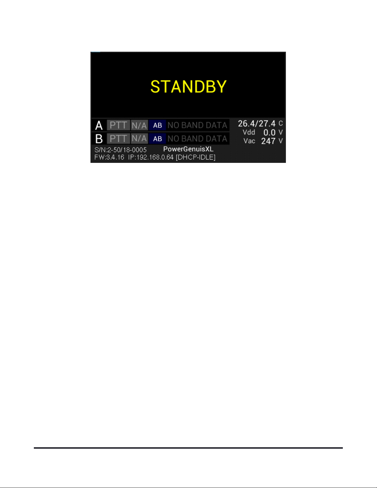
When the power-on-self-test completes the amplifier will enter STANDBY mode.

Page 13 of 73
Copyright 2023 FlexRadio. All Rights Reserved. 4 January 2023 (FW:3.7.28 Utility:3.7.28)
3.2 Configuring for use in FlexRadio environments
When the Power Genius XL is used in a FlexRadio environment, the amplifier should be connected to the Local
Area Network (LAN) with the supplied Ethernet cable and must be configured to work with the transceiver or
transceivers that will drive it. The basic configuration of the amplifier is accomplished using the Power Genius
XL Utility program. Please see section 15.1, Installing the Power Genius XL Utility, for installation instructions.
When the amplifier is ready to configure, it should be connected in a fashion similar to the following:
3.2.1 Connecting the Power Genius XL Utility program
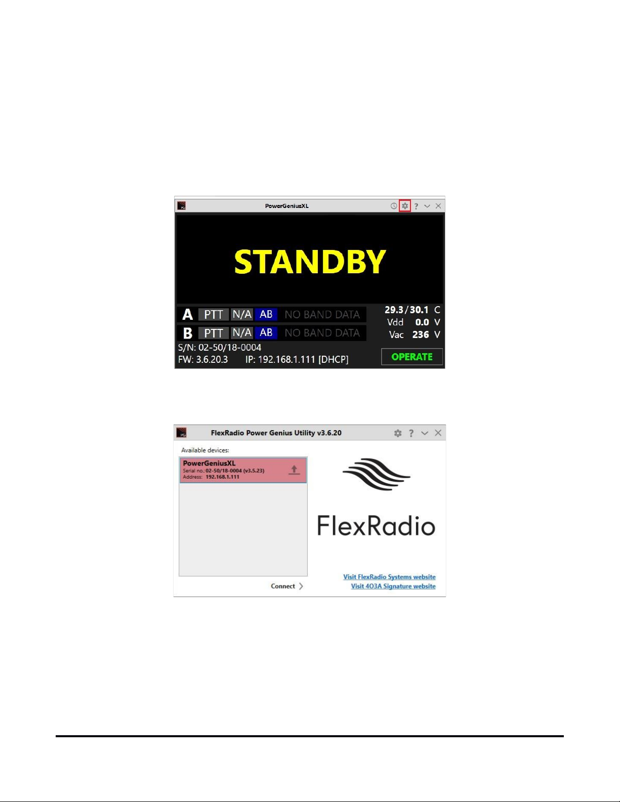
Start the Power Genius XL Utility program. It will automatically discover your Power Genius XL amplifier, and
you should see something like this:
If you do not see your Power Genius XL in the Available devices list, please:
•Double-check your network connections and cables.
•Ensure the Power Genius XL is powered on, and an IP address is displayed on the front panel. See
section 3.1, Unpacking and Initial Setup for details.
•Check that the PC's firewall is configured to allow the Power Genius XL Utility to communicate over
your network. Opening a port in the firewall usually is performed during the utility installation process.
Page 14 of 73
Copyright 2023 FlexRadio. All Rights Reserved. 4 January 2023 (FW:3.7.28 Utility:3.7.28)
•Check that your PC and Power Genius XL share the same logical network. The IP address of your PC and
the Power Genius XL should be similar, though not identical.
•If you still have trouble, please submit a HelpDesk ticket for assistance.
Click on your amplifier to select it, then click on the Connect button.
Once connected, an amplifier status screen will appear, like the image below. Click on the configuration settings
button (outlined in red) to open the amplifier's Device settings screen and then continue to section 3.2.2,
Network Tab: Set a Custom Device Name to set up the amplifier's configuration.
If you see a screen similar to the following, please proceed to section 10, Firmware Upgrade Procedure to
upgrade the amplifier’s firmware to the version that corresponds to the Power Genius XL Utility program.

Page 15 of 73
Copyright 2023 FlexRadio. All Rights Reserved. 4 January 2023 (FW:3.7.28 Utility:3.7.28)
3.2.2 Network Tab: Set a Custom Device Name
You can customize your Power Genius XL by configuring a device name to uniquely identify your amplifier. This
name will appear on the amplifier's front panel, in the utility Available devices list, and the utility's main
window.
•Select the Network Tab on the Configuration screen.
•Enter an appropriate name in the Device name field.
•Click Save
i – The amplifier will reboot when Save is clicked.
i – You do not need to click Save after every configuration change. You can postpone it until you have
completed all the configuration steps, but you must click Save at some point to save the configuration for
later use.
3.2.3 Network Tab: Configuring the Network
The Power Genius XL is configured at the factory (or after a factory reset) to use DHCP IP addressing and will
automatically secure an IP Address appropriate for your network when it starts. This configuration should be
sufficient for most situations.
You can use the Network tab to assign a static IP Address, a static Network Mask, and a Gateway address. Static
IP addresses are desirable in some network configurations but require specific technical knowledge of the

Page 16 of 73
Copyright 2023 FlexRadio. All Rights Reserved. 4 January 2023 (FW:3.7.28 Utility:3.7.28)
network. Most configurations will not require these steps. If you don’t need any of these options, please
proceed to the next section.
The network settings screen performs basic validation of the network settings. Note the red X next to an
incorrectly formatted subnet mask below.
If you are not familiar with the rules of setting or using static IP addresses but believe you need to configure
one, please submit a HelpDesk ticket for assistance.
When you have completed the network configuration, click Save to instruct the Power Genius XL to save the
configuration before performing the next step.
i – The amplifier will reboot when Save is pressed.
i – It is unnecessary to exit and restart the Power Genius XL Utility after Save is pressed.
i – If incorrect network information was saved, please follow the instructions in section 11, Factory Reset the
Power Genius XL.
Once you have pressed save, the configuration dialog will close, and the Power Genius XL Utility will wait for
the amplifier to reboot.
The utility will reconnect to the amplifier when it appears on the network.

Page 17 of 73
Copyright 2023 FlexRadio. All Rights Reserved. 4 January 2023 (FW:3.7.28 Utility:3.7.28)
Before moving to the next step, please click the configuration (gear) icon.

Page 18 of 73
Copyright 2023 FlexRadio. All Rights Reserved. 4 January 2023 (FW:3.7.28 Utility:3.7.28)
3.2.4 FlexRadio Tab: Configuring for a FLEX-6000 Series Transceiver.
To pair the amplifier for use with a FLEX-6000 Signature Series transceiver, turn the radio on, then click on the
FlexRadio tab in the Power Genius XL Configuration screen:
Location of Radio SN
Select the discovered Radio SN
Enable: Each of the port configuration windows contains an enable switch. When this switch is off (not
checked), the amplifier will ignore any Flex radio configured for that port. The configuration fields will be
dimmed and no changes to the configuration can be made. Click the Enabled check box to activate the
configuration information for the amplifier port. The ports can be enabled and disabled without altering the
configuration information.
Serial Number: The utility program will detect your FLEX-6000 transceiver(s) automatically. If your radio is
connected to Port A of the amplifier, click on the Port A serial number drop-down list, and select your radio. You
can find your radio's serial number on a sticker on the back panel of the radio or in the Smart SDR Radio Setup
dialog as shown above. If a FLEX-6000 transceiver is connected to Port B, make the Port B configuration settings
similarly.
It is not required that you connect ANT1 output on a FLEX-6000 Signature Series connect to Port A input on the
amplifier. Any FLEX-6000 antenna output can be connected to any Power Genius XL Port. However, it is required
that the configuration match the physical connections.
TX Antenna: This field configures the amplifier to follow frequency changes on the port and automatically
switches in the correct output filters. For example, if ANT1 on a FLEX-6000 transceiver is connected to amplifier
Port A input, select ANT1 as value for the Port A Configuration section. When ANT1 is selected for transmitting
on a slice, the amplifier will make the corresponding changes to its output filters. The selected band will appear
on the amplifier's front panel and the utility program’s screen.

Page 19 of 73
Copyright 2023 FlexRadio. All Rights Reserved. 4 January 2023 (FW:3.7.28 Utility:3.7.28)
ANT1 is Connected to Port A, LAN PTT
ANT2 is Connected to Port A, LAN PTT
When driven by a FLEX-6000 Signature Series transceiver, the amplifier can be keyed over the radio's LAN
connection. This option is strongly recommended; however, you can use a PTT signal wire connected to the
appropriate RCA PTT Input on the amplifier back panel. A twenty millisecond (20ms) TX delay must be set for
each Transmit profile that uses the Power Genius XL if you do. Select the desired keying source in the PTT
Source box on the configuration screen for each radio. LAN keying manages all the necessary transmit delays
automatically.
When the same FLEX-6000 transceiver is connected to both Power Genius XL ports (A and B), you must select
the same serial number for both Port A and B sections. This configuration enables advanced Single Operator
Two Radio (SO2R) operations, with a single transceiver and amplifier.
SO2R Configuration ANT2->Port A, ANT1->Port B
Click the Save button to record the configuration in the amplifier. The Power Genius XL amplifier is now
configured for use by the FLEX-6000 Signature Series transceiver. Please proceed to section 3.6, Testing to
complete the setup.
! – Do not connect another transceiver via RS-232 (CAT), CI-V, or BCD to the same amplifier Port configured
for a FlexRadio transceiver.
i – Do not connect a PTT line when interfacing with a FLEX-6000 transceiver. Unless some advanced need
requires a separate PTT signaling wire, LAN signaling is all you need.
i – The LAN integration of the Power Genius XL amplifier is supported in SmartSDR Version 2.0 and later
versions. It is not supported in SmartSDR Version 1.

Page 20 of 73
Copyright 2023 FlexRadio. All Rights Reserved. 4 January 2023 (FW:3.7.28 Utility:3.7.28)
3.3 Configuring for use with stand-alone FlexRadio M model transceivers.
When the Power Genius XL is used in a stand-alone FlexRadio environment (a FlexRadio Signature Series 6400M
or 6600M with no Local Area Network connection), the amplifier is connected directly to the transceiver and
configured using the Front Panel Configuration tool. See section 3.4.2, Configure Using the Front Panel for
instructions on the use of this tool. Once configured, the amplifier will follow all frequency and mode changes
and transmissions made by the transceiver.
In the stand-alone configuration the following limitations apply:
•The Power Genius XL Utility program cannot be used to monitor the amplifier locally or remotely.
•Only one FlexRadio transceiver can be connected to the amplifier, however other makes of transceivers
can be connected following the instructions in section 3.4, Configuring for Use with Other Exciters.
•The amplifier will need a few extra seconds after it starts to find the FlexRadio transceiver and show the
connection on the front panel.
Other manuals for Power Genius XL
3
Table of contents
Other FlexRadio Amplifier manuals


