Flextest FL2005.1 User manual
FLEXTEST Multifunctional Tester
FL2005.1
INSTRUCTION MANUAL
CONTENTS
Title Page
1. SAFETY INFORMATION..................................................1
2. SPECIFICATIONS …........................................................2
3. PARTS & CONTROLS......................................................4
4. BEFORE OPERATION......................................................7
5. V VOLTAGE MEASUREMENT........................…........9
6. FLOOR PROBE RESISTANCE MEASUREMENT...…..…....9
7. HEATING CABLE RESISTANCE <1000Ω
MEASUREMENT.....………..………………….…………...9
8. MΩINSULATION RESISTANCE MEASUREMENT......10
9. BATTERY REPLACEMENT..................................…......11
10. MAINTENANCE & CLEANING.....................................11

1. SAFETY INFORMATION
The circuit under test must be de-energized and isolated before
connections are made except for voltage measurement.
Verify operation prior to measuring hazardous voltages (voltage
above 30V AC rms, 42V AC peak and 60V DC).
Do not touch the circuit connections during a test.
Disconnect the live test lead before disconnecting the neutral
test lead.
After insulation tests, to protect from electric shock, capacitive
circuits must to be discharged.
Do not use the meter if the low battery indicator ( BT ) is
displayed.
Test leads (including crocodile clips) must be in good order,
clean and not broken nor cracked.
Do not use the meter if it looks damaged.
Do not use the meter around explosive gas, vapor or dust.
Do not push test button before all connection and preparation is
done. The instrument must only be used by suitably trained and
competent persons.
Do not use the meter with any parts or cover removed.
Do not use the meter in a wet environment.
U.S. PAT. NO. 478,017
JAPAN PAT. NO. 1180870
CHINA PAT. NO. ZL02367250.1
Warnings and Safety symbols:
Caution refer to this manual before using the meter.
Dangerous voltages.
Meter is protected throughout by double insulation or
reinforced insulation.
Comply with IEC1010-1
When servicing, use only specified replacement parts.
2. SPECIFICATIONS
2-1 General Information
Environment conditions :
cInstallation Categories III 1000V
d
Pollution Degree 2
eAltitude up to 2000 meters
fIndoor use only
Safety Meets of IEC61010-1 and IEC61557
Display : Dual display, 3-3/4 Digital readout with analog bar
indication.
Sampling Rate : 1 sample/sec.
Manual data Memory and Read : Memory capacity 9 set.
Over Range Indicator : “ ” will be displayed.
Low Battery Indication :
The ( BT ) will be displayed when the battery voltage drops
below the operating voltage.
Operating Temperature and Humidity:
0℃to 50℃(32℉to 122℉) below 80% RH (noncondensing).
Temperature Coefficient : 0.10 x (specified accuracy)/ ℃
Storage Temperature and Humidity :
-10℃to 60℃(14℉to 140℉) below 70% RH (noncondensing)
Battery : 6 x 1.5V Size “AA” battery.
Dimensions : 235 (L) x 116 (W) x 54(H) mm ,
(9.3”L x 4.6”W x 2.1”H)
Weight : Approx. 520g (1.15 LB), including battery
Accessories : Test leads, 6pcs batteries, carrying case,
instruction manual, reference card
2

2-2 Electrical Specifications
Accuracies are specified as:
±(...% of reading + ...digits) at 23℃±5℃,below 80% RH.
Insulation Resistance (MΩ)
Range Resolution Accuracy Test Voltages
250V
2MΩ/20MΩ/
200MΩ/ 2GΩ/4GΩ
2MΩ: 1KΩ
20MΩ: 10 KΩ
200MΩ:100 KΩ
2GΩ:1MΩ
10GΩ:10MΩ
250V+30% ~ -0%
500V
4MΩ/40MΩ/
400MΩ/2GΩ/ 4GΩ
4MΩ: 1KΩ
40MΩ: 10KΩ
400MΩ:100 KΩ
2GΩ:1MΩ
10GΩ:10MΩ
500V+30% ~ -0%
1000V
4GΩ1MΩ
3%+5
(<1000M)
5%+5
(>1000M)
1000V+30% ~ -0%
Analog Bar Graph 0 to 10GΩ
Nominal Current ≧1mA
HEATING CABLE Resistance <1000Ω
Range Resolution Accuracy Max. open Circuit
Voltage
Overload
Protection
999.9Ω0.1Ω1%+10 ≦3V 600Vrms
FLOOR PROBE Resistance
Range Resolution Accuracy Max. open
Circuit Voltage
Overload
Protection
99.99KΩ0.01KΩ1%+5 ≦3V 600Vrms
3
~V AC Voltage (40Hz~500Hz)
Range Resolution Accuracy Input Impedance Overload
Protection
999V 1V 2%+3 9MΩ1000Vrms
Sensitivity : 2V
V DC Voltage
Range Resolution Accuracy Input Impedance Overload
Protection
999V 1V 2%+3 9MΩ1000Vrms
Sensitivity : 2V
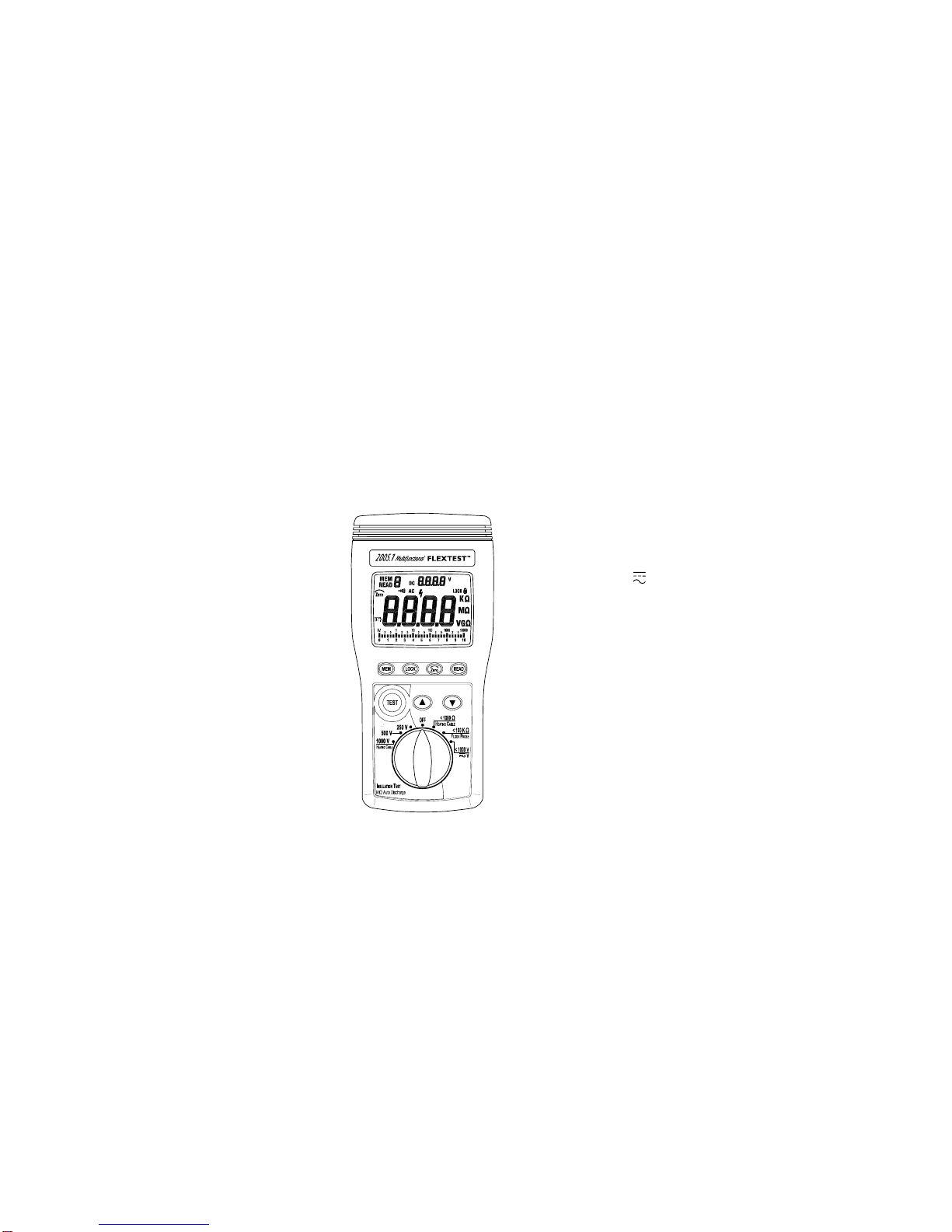
3. PARTS & CONTROLS
1
2
3
6
4
10
5
7
8
9
4
cLCD display.
dMEM key: Manual data memory control key.
eLOCK key: Locks the test Insulation Resistance (MΩ).
a) Press and hold down LOCK key than press TEST key enter to
continuously MΩtest mode, the “LOCK ” icon appear on the
display.
b) In MΩmode continuously applies the test voltage to the circuit to
be tested. The beeper sounds every 2 seconds to remind you
that you are in the LOCK mode.
c) Press the LOCK or TEST key to stop the test.
fREAD key: Manual memory data read control key.
gkey: In HEATING CABLE <1000Ωfunction, turns the test lead
resistance compensation ON.
Touch the probe tips together, then press key.
The icon will appear on the display and the main
display indicates 0.0Ω.
hTEST key:
a). Used for MΩtest functions.
b). Press and hold TEST key until the main display measurement
has stablized.
ij▼▲ keys : In READ mode, select the data memory location to
display the data.
kRotary switch: To select a measurement function.
lInput terminals.
5
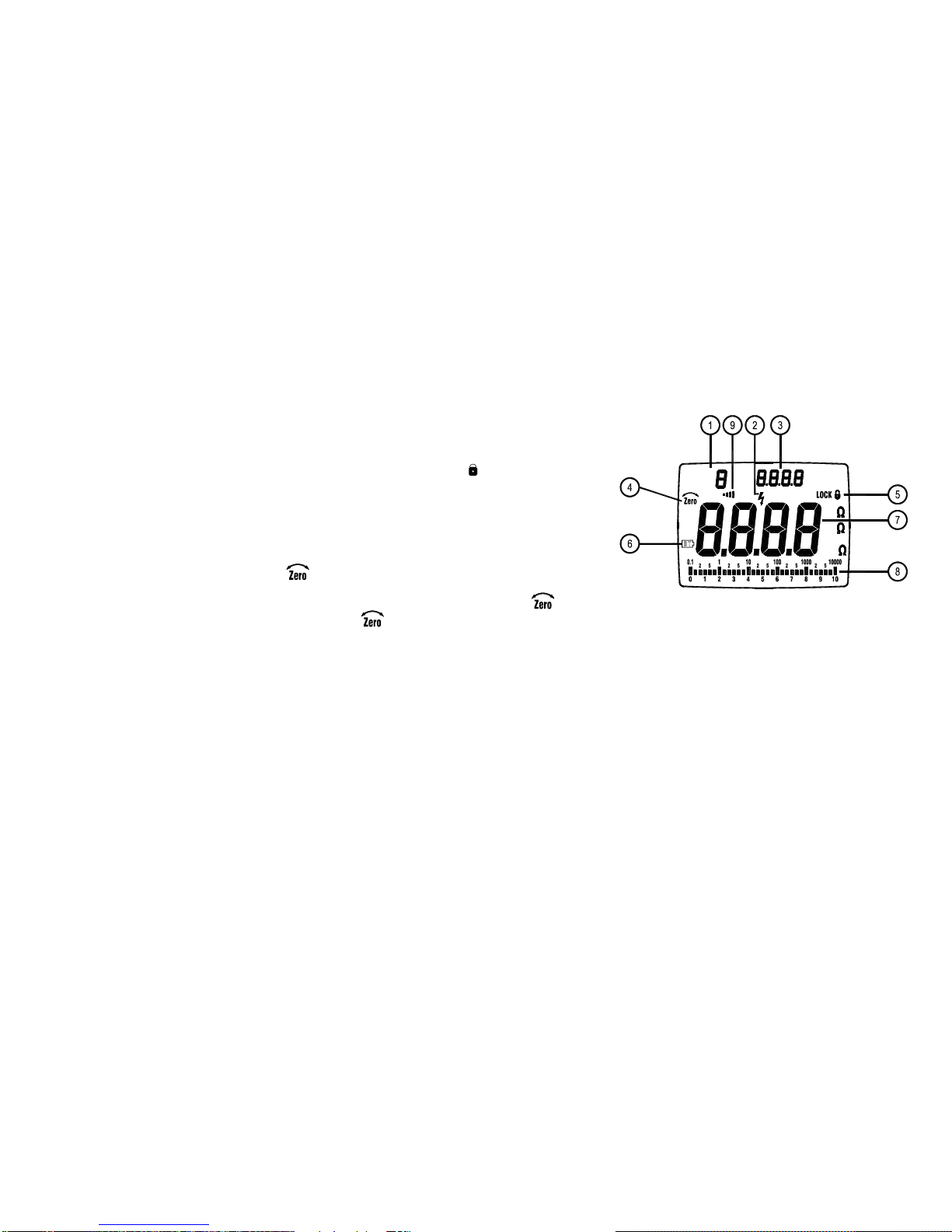
Display :
K
VG
M
READ
MEM DC
AC
V
cManual data memory and read address indicator.
dIn MΩranges, high voltage warning symbol flashes.
eIn MΩfunctions indicates the test voltage applied to the circuit under
test.
fZero symbol is on if test leads are zeroed out.
gLock symbol is on if the TEST mode is locked in MΩfunctions.
hLow battery symbol.
iMain display reading for all functions.
jAnalog bar graph displays MΩon a logarithmic scale and other
functions on a linear scale. The value always tracks the main
display.
kIn HEATING CABLE <1000Ωfunction, the beeper symbol indicates
input resistance <10Ω.
6

4. BEFORE OPERATION
Warning
To avoid electrical shock remove test leads before opening case or
battery cover. Do not operate with battery cover open.
To avoid electrical shock when performing resistance tests, remove
all power from the circuit to be measured.
To avoid electrical shock, first connect the test leads to the meter
inputs before you make connection to the circuit under test.
To avoid electrical shock, do not touch test lead tips, test points or
terminals when pressing TEST.
4-1 How to connect test leads.
Connect the red test lead into the “ VΩ” terminal and the black
lead into the “ COM ” terminal.
4-2 Battery Check & Replacement
1) If battery power is not sufficient, LCD will display “ BT ”.
Replacement of 6 pcs new batteries, type 1.5V size “AA” is required.
2) Use a screwdriver to unscrew the screw secured on battery cover.
Take out the used batteries and replace 6 pcs new batteries.
3) Replace the battery cover and secure the screw.
4-3 Test Leads Check
Set the range select switch to the HEATING CABLE range. Connect
the crocodile clips with the test lead tips, Clip alligator clips with
lead other. The indicator should read <0.5Ω. When the leads are
not connected the display will read infinity indicated by “ .”. This
will ensure that test leads are under working condition.
7
4-4 Manual Data Memory and Read Mode :
1) Clear the manual memorized data
cSet the function switch to OFF position to turn off the meter.
dPress and hold down "MEM" key, and turn on the meter.
Release the "MEM" key. When LCD shows "MEM CLr" mark,
press “▼” key select “YES” or “NO”, then press “MEM” key to
exit this mode. To clean all of the memories, select “YES”.
2) Manual data memory
cPress "MEM" key each time, one set of reading will be stored
to the memory. At this moment, LCD will show the "MEM"
mark and the memory address number. Total memory size is
9 sets.
dWhen the memory is full, LCD will show " F " memory address
number.
3) Read Manual memory data
cPress "READ" key to enter READ mode, the LCD will show
"READ" mark and the memory address number.
dPress "▲" or " ▼" key to select the desired memory address
number data for display.
ePress " READ " key again to exit this mode.
8

5. VVOLTAGE MEASUREMENT
1) Set the function switch to V position.
2) Connect red test lead to “ VΩ” terminal and black test lead to
“ COM ” terminal.
3) Connect the probe IN PARALLEL to the circuit to be measured.
4) Read the voltage value from the display. The meter indicates AC
voltage on the main display.
6. FLOOR PROBE - RESISTANCE MEASUREMENT
1) Set the function switch to FLOOR PROBE position.
2) Connect red test lead to “ VΩ” terminal and black test lead to
“ COM ” terminal.
3) Connect the probe to floor probe wires.
4) Read the resistance value from the display.
7. HEATING CABLE <1000ΩRESISTANCE MEASUREMENT
1) Set the function switch to HEATING CABLE <1000Ωposition.
2) Connect red test lead to “ VΩ” terminal and black test lead to
“ COM ” terminal.
3) Zero out the test lead resistance (see section 3.5 Zero key).
4) Connect the probes to the cable wires (black & white / red).
5) Read the resistance value from the display, if the resistance is
<10Ω, the meter will beep.
9
8. MΩINSULATION RESISTANCE MEASUREMENTS
8-1 Measuring Insulation Resistance
Measuring insulation resistance requires the application of
potentially dangerous voltage to the circuit. This may include
exposed bonded metal work.
Before proceeding, ensure that the installation is correctly wired
and no personnel are endangered by any test.
1) Set the function switch to the desired MΩtest voltage position.
2) Connect red test lead to “ VΩ” terminal and black test lead to
“ COM ” terminal.
3) The display will show “-----” until the TEST button is pushed.
Press and hold the TEST key. The upper right display shows
the test voltage applied to the circuit under test. The main
display shows the resistance until a stable resistance reading is
displayed on the main display.
4) Keep the probes on the test points when releasing the TEST
key. The upper right display shows the measured resistance
reading and the main display show “- ---”, while the circuit now
discharges through the meter.
5) Verify that the circuit is completely discharged. Set the function
switch to the other MΩtest voltage position. The upper right
display shows the decreasing voltage, keep the probe touched
to test points until the circuit is completely discharged and the
display shows “0V”.
8-2 Using the LOCK Function to Measure Insulation Resistance
The LOCK function holds the test voltage on the probes. Use
LOCK function to make long duration measurements, don’t need
to push and hold the TEST key.
1) Press and hold down LOCK key then press TEST key enter to
LOCK mode. In this mode, a potentially dangerous voltage is
continuously applied to the probes.
10

In this mode, if the probes are disconnected from the circuit, the
meter cannot discharge any potentially dangerous capacitive
voltages left on the circuit.
Ensure that the circuit is de-energized before connecting the test
probes.
2) Press LOCK or TEST key to disable the Lock function.
9. BATTERY REPLACEMENT
1) Set the function switch to OFF position.
2) Disconnect test leads from any power source.
3) Place the meter face down on a nonabrasive surface and loosen
the two screws.
4) Take off the battery cover.
5) Remove the battery, replace with six new batteries.
6) Place the battery cover on and secure the two screws.
10. MAINTENANCE & CLEANING
1) Repairs or servicing not covered in this manual should only be
performed by qualified personnel.
2) Periodically wipe the case with a dry cloth.
Do not use abrasives or solvents on this instrument.
11
Sep-2006-1
Table of contents
Popular Test Equipment manuals by other brands


Rolls
Rolls CABLE SCANNER CS1000 owner's manual

Extech Instruments
Extech Instruments CT70 user manual

Hach
Hach MTC301 user manual

Anritsu
Anritsu MT1000A Network Master Pro Operation manual

PCB Piezotronics
PCB Piezotronics 8159-0153A Installation and operating manual

HYDAC FILTER SYSTEMS
HYDAC FILTER SYSTEMS CTU 1 3 Series Operating and maintenance instructions