Tyco T210+ Manual

LEAFLET S/C 120.415.482
© 2006 Tyco Safety Products PAGE 1 of 5
T210+ TEST SOURCE
FIL 0055
42/06
T210+ TEST SOURCE - OPERATING INSTRUCTIONS
1. INTRODUCTION
The T210+ Test Source is used to test Thorn Security S200 and
S200+ Series of infra-red flame detectors in both safe and
hazardous areas.
The T210+ is ATEX/IECEx approved for use in zones 1 and 2
for group IIC gasses rated T1 - T4. Approval for zone 0 is not
available for this type of equipment, although it is understood
that dispensation may be obtainable on a site-by-site basis from
the Factory Inspectorate.
WARNING:
UNDER NO CIRCUMSTANCES OPEN THE
T210+ HOUSING IN A HAZARDOUS AREA.
BATTERY CHANGES MUST BE MADE IN A
SAFE AREA.
2. DESCRIPTION
The T210+ consists of a module mounted in a cradle which can
be hand held or secured to an extendable pole. The module is
self-aligning on the detector by means of an adaptor secured to
the front of the cradle. The assembly is then held against the
detector to check the response time and sensitivity of the
detector.
The Test Source is enclosed in a glass filled polyester housing
which is approved as an increased safety or ‘e’ housing. It
contains a bulb which is electrically pulsed by an intrinsically
safe circuit to simulate typical flame flicker. Infra-red radiation
from the lamp is focused by a parabolic reflector through a
sapphire window onto the detector.
The unit is powered by a Baseefa approved PP3 battery (see 5.4).
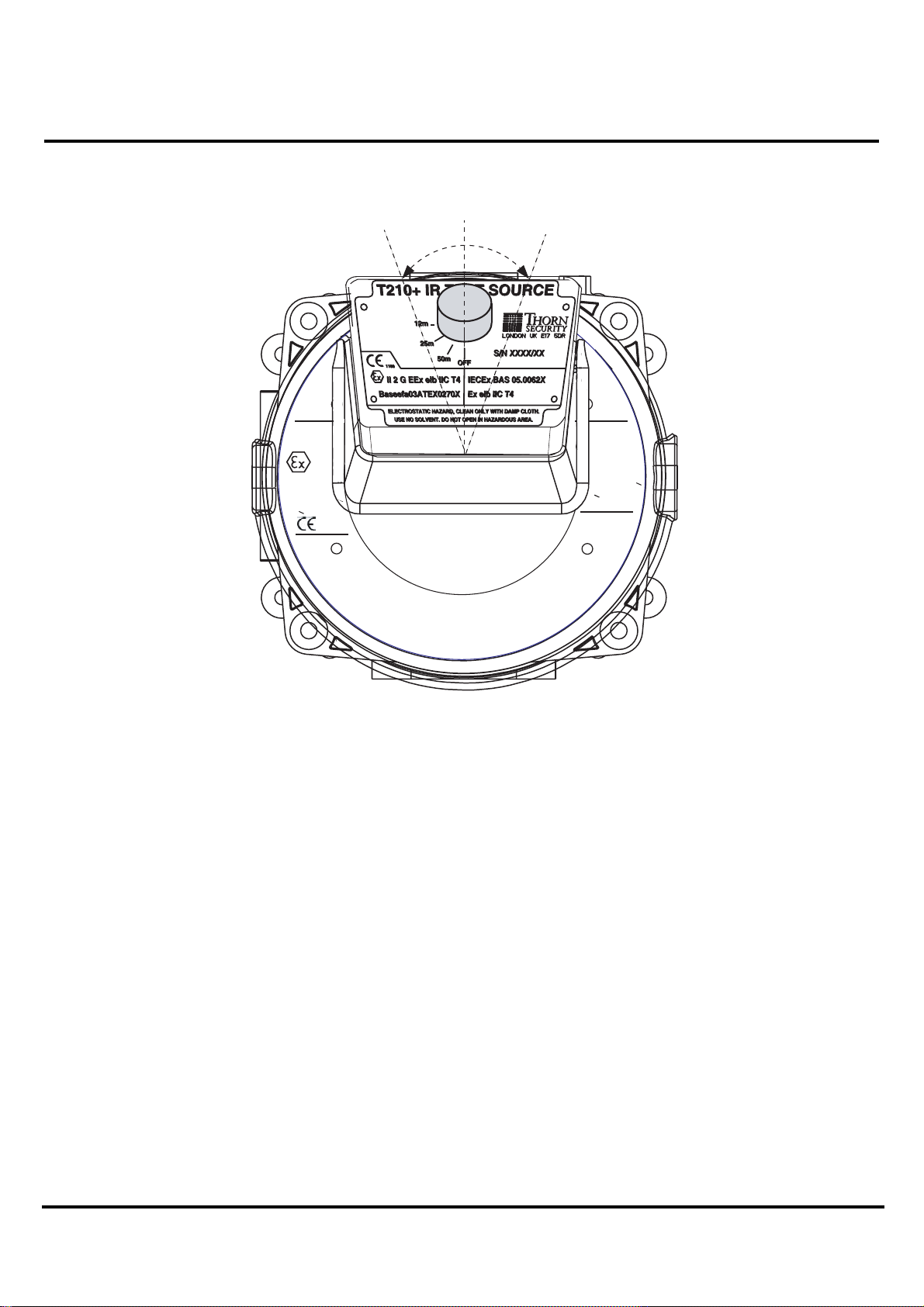
The T210+ is switched on with a rotary selector switch knob
located on the rear of the unit.
The switch has four positions:
1) OFF Off
2) 50m To test detectors set to 50m
range
3) 25m To test detectors set to 25m
range
4) 12m To test detectors set to 12m
range
Care must be taken to switch off the unit when not in use to avoid
battery drain.
3. PREPARING T210+ FOR USE
1) To assemble the T210+ to the S200 adaptor S/C No.
592.001.014, see Fig 1.
a) Assemble the S200 adaptor moulding/‘U’
bracket to the T210+ front plate using the three
screws provided.
b) Attach the pole bracket to the ‘U’ bracket/pole
stub assembly using the wing nut and nylon
washers provided. Tighten securely.
Note: Hereafter, the term T210+, refers to the T210+
fitted with the S200 adaptor, brackets and pole
stub.
2) To fit battery (in safe area) see below.
a) Ensure that the PP3 battery is fully charged.
b) Ensure that the T210+ rotary switch is in the
‘OFF’ position.
c) Remove the four back cover corner screws. Lift
off the box front containing the PCB and battery
holder. A lanyard is fitted to the T210+ to avoid
straining the lead connecting the lamp assembly
on the front box to the PCB on the back box.
d) Align the PP3 battery with the battery holder,
ensuring correct polarity alignment and push the
battery into the holder.
Note: The circuit is polarity protected but the unit will not
work with battery inserted the wrong way round.
e) Turn the rotary switch to the 12m position and
check that the lamp flashes. Turn the rotary
switch to the 25m position and check that the
lamp flashes more dimly. Turn the rotary switch
to the 50m and check that the lamp is very dim.
f) Turn the rotary switch to the OFF
position. Reassemble the back case to the front
cover with the four screws. Do not over tighten.
WARNING:
THIS IS A CALIBRATED UNIT. DO NOT
DISMANTLE THE REFLECTOR CLAMP
ARRANGEMENT.

T210+ TEST SOURCE
FIL 0055
42/06
PAGE 2 of 5
4. TEST
WARNING:
TESTING A DETECTOR WILL PRODUCE AN
ALARM SIGNAL FROM THE DETECTOR. TAKE
THE NECESSARY STEPS TO INHIBIT A FULL
ALARM CONDITION AT THE CONTROL PANEL
BEFORE PROCEEDING.
a) If the detector for test cannot be reached by arm
extension, connect up extension poles to the
required length, (up to 3.9m: 13ft).
b) The T210+ is calibrated with the T210+ aligned
with the front face of the S200 (see Fig. 2). It is
therefore recommended that the operator adjusts
the swivels on the T210+ bracket to line up the
T210+ with the S200 detector on the ground prior
to fitting the extension poles. The T210+ unit
should be approximately aligned with the cable
entry holes on the S200.
c) Turn the rotary switch to the detector range
required.
d) Offer up test unit to the front of the detector and
engage top of the front surround on the top edge
of the detector. Check that the T210+ is
correctly aligned as per Fig. 2. If not, lower the
T210+ and readjust swivels until the T210+
aligns correctly within the specified limits.
e) Push forward on the handle or extension and the
T210+ will self align to the face of the detector.
f) Hold in position for 30 seconds, the detector
alarm LED should illuminate, indicating that the
detector has responded correctly.
g) Lower test unit and turn rotary switch to the
‘OFF’ position
5. TECHNICAL SPECIFICATION
5.1 MECHANICAL
Materials
Housing: Glass filled polyester two
part case sealed to IP54.
S200 Series Adaptor: Clear Polycarbonate.
Pole + Bracket: Stainless steel.
Pole Stub: Aluminium.
Wing Nuts: Stainless steel.
S200 ADAPTOR
MOULDING
SOLO704
ADAPTOR TUBE B
517.001.224
SOLO101 EXTENSION TUBE (517.001.226)
SOLO100 TELESCOPIC POLE (517.001.230)
POLE BRACKET
POLE STUB
'U' BRACKET
NOTE: S200 ADAPTOR (592.001.014
CONSISTS OF:
S200 ADAPTOR MOULDING,
'U' BRACKET, POLE BRACKET
AND POLE STUB
Fig. 1 T210+ Test Source and S200 Series Adaptor

T210+ TEST SOURCE
FIL 0055
42/06
© 2006 Tyco Safety Products PAGE 3 of 5
S241i+
Serial No.
IECEx
R
E
G
I
S
T
E
R
E
D
D
E
S
I
G
N
A
P
P
L
I
C
A
T
I
O
N
N
o
.
2
0
3
1
9
5
4
,
P
A
T
E
N
T
E
D
U
i
=
2
8
V
l
i
=
9
3
m
A
P
i
=
0
.
6
5
W
C
i
=
1
n
5
L
i
=
0
XXXXX/XX
LONDON UK TW16 5DB
Baseefa02
ATEX 0257
EEx ia IIC T5
II 1 G
1180
or T4(-40 C <
Ta < +80 C)
0
0
EN 54-10:2002
143k/02
BAS05.0051
Ex ia IIC T5
or T4(-40 C<
Ta< +80 C)
0
0
2
THE T210+ TEST SOURCE MUST BE POSITIONED AS SHOWN
20 DEGREES FOR CORRECT OPERATION.
+
-
-20 +20
oo
Fig. 2 T210+ Alignment
Weight
T210+ Test Unit with adaptor: 1.0kg.
Extension Pole: 3.0kg.
5.2 ENVIRONMENTAL
Temperature
Operating: -10oC to +50oC
Storage: -30oC to +70oC
Humidity Up to 95%
[non-condensing]
EMC: Equals or exceeds the
requirements of
EN 50130-4 (immunity)
EN 61000-6-3 (emissions)
5.3 BATTERY LOW INDICATOR
There is a battery low indicator behind the small window on
the front of the T210+. This will flash periodically to
indicate the battery charge is low. When this indicator lights
permanently, this indicates that the battery charge is too low
to continue testing detectors. The T210+ must then be taken
to a Safe Area and the battery changed.
5.4 BATTERIES
Two rechargeable PP3 batteries are approved for use with
the T210+:
•VARTA V7/8H NiMH. This is available
from Farnell - Part No. 521-516.
•GOLD SEAL GP15F8K NiCad.
(These batteries have been tested for safe operation under
short circuit conditions).

T210+ TEST SOURCE
FIL 0055
42/06
PAGE 4 of 5
Standard Nickel Carbon and Zinc Chloride PP3 6F 22-IEC
batteries are also Baseefa approved. However, these are not
recommended as they are required to be replaced more often
(typically 2 hours continuous use as opposed to 4 hours for
rechargeable PP3 batteries).
No alternative batteries may be used as this will invalidate
the approval for use in Hazardous Areas.
The recommended charging time NiMH battery is:
Normal Charging: 14mA for 14h
Accelerated Charging for
fully discharged cell: 70mA for 3h
Trickle Charge: 4.2mA
5.5 ATEX CERTIFICATION
The T210+ is certified against EN50014, EN50019
(Increased Safety ‘e’) and EN50020 (Intrinsic Safety ‘i’).
The T210+ is certified:
II 2 G eib IIC T4
The certification covers the use of the T210+ in Zone 1 and
Zone 2 areas over the ambient temperature range -20°C to
+40°C.
The label is shown in Fig. 3.
The ATEX Certification number is Baseefa03ATEX0270X.
5.6 IECEx CERTIFICATION
The T210+ is certified against BS EN 60079-0 and EN
50020. It is classified T4 for use in ambient temperatures
between -20°C and +40°C.
The IECEx classification is shown on the label in Fig. 3 as
Ex eib IIC T4
and the IECEx certification number is IECExBAS
05.0062X.
Fig. 3
6. PERFORMANCE
The T210+ produces a modulated test stimulus for 14 to 16
seconds to allow all S200/S200+ detectors to be tested
(S200/S200+ time to alarm settings are 3, 6 and 12seconds).
The T210+ set to 12m range. On this setting the T210+ is
set up to simulate a 0.1 sq m n-heptane fire at a range of 8.5
to 10.5m.
The T210+ set to 25m range. On this setting the T210+ is
set up to simulate a 0.1 sq m n-heptane fire at a range of 14
to 18m.
The T210+ set to 50m range. On this setting the T210+ is
set up to simulate a 0.1 sq m n-heptane fire at a range of 28
to 36m.
7. REPLACEMENT OF THE
BATTERY
WARNING:
UNDER NO CIRCUMSTANCES MAY THE
T210+ BE OPENED (OR THE BATTERY
REPLACED) WHILE IN A
HAZARDOUS AREA.
ONLY FIT APPROVED BATTERIES, SEE 5.4.
Follow the procedure detailed in Section 3. step 2). It is
recommended that a fully charged battery is fitted prior to
using the T210+ and that spare fully charged batteries are
also made available if a large number of detectors are to be
tested.
8. CLEANING
Do not rub or clean the T210+ with solvent as this could
cause an electrostatic charge and a risk of explosion in the
presence of an explosive gas. Clean only with a damp cloth.
9. REPAIR OF DAMAGED UNITS
The T210+ is a calibrated unit. On no account may the front
and rear box assemblies be interchanged between units.
If a T210+ becomes non-functionalor damaged, it should be
returned for repair and recalibration to:
Service Department
Tyco Safety Products
Dunhams Lane
Letchworth
Herts
SG6 1BE

T210+ TEST SOURCE
FIL 0055
42/06
© 2006 Tyco Safety Products PAGE 5 of 5
10. ORDERING INFORMATION
T210+ infra-red test source: 592.001.016
Adaptor S200 series: 592.001.014
Nicad battery and charger: 592.001.010
Solo 100 telescopic extension pole set: 517.001.230
Solo 101 extension pole: 517.001.226
Solo 704 adaptor tube B: 517.001.224
Solo 610 Carryall bag: 517.001.264
JM/tg
1st February 2006
Table of contents
Other Tyco Test Equipment manuals
Popular Test Equipment manuals by other brands

Vigor Equipment
Vigor Equipment V7524 operating instructions

The Diagnostic Box
The Diagnostic Box TDB003 operating manual

Associated Research
Associated Research HYAMP 3240 Service manual

Kett
Kett HK-300-1 operating manual

Hasco
Hasco Z141/3 operating instructions

VOLTCRAFT
VOLTCRAFT VC MFK-2000 operating instructions

CSZ
CSZ Z-Plus quick start guide

Hisense
Hisense HKF-D1EC Instructions for installation, use and maintenance manual

barfield
barfield DFQ40K User instruction manual

Tektronix
Tektronix 2445A Service manual

Compliance West
Compliance West MegaPulse Antenna Surge PF 65 instruction manual

Bacharach
Bacharach 2810 brochure