manuals.online logo
Brands
  1. Home
  2. •
  3. Brands
  4. •
  5. YOKOGAWA
  6. •
  7. Test Equipment
  8. •
  9. YOKOGAWA 2553A User manual

YOKOGAWA 2553A User manual

User’s
Manual
IM 2553A-71EN 1/8
2nd Edition
2nd Edition : October 2017 (YMI)
All Rights Reserved, Copyright © 2014, Yokogawa Test & Measurement Corporation
Printed in Japan
Model 2553A
Precision DC Calibrator
Simple Adjustment Procedure
Have a qualified engineer perform simple adjustment of the 2553A at a specialized facility with sufficient
precision. The simple adjustment values are retained even when the settings are initialized.
If you need to adjust the 2553A more accurately than that is possible with the simple adjustment feature or if you
want calibration and adjustment to be performed at a YOKOGAWA factory, contact your nearest YOKOGAWA
dealer. If calibration and adjustment are performed at a YOKOGAWA factory, all settings including the simple
adjustment values will be initialized to their factory default values.
WARNING
• Groundtheinstrumentbeforeconnectingtheinstrumenttothetargetdevice.Thepowercord
that comes with the instrument is a three-prong type power cord. Insert the power cord into a
grounded three-prong outlet.
• Besuretoturnofftheoutputbeforeconnectingordisconnectingthetargetdevice.
French
AVERTISSEMENT
• Relierl’instrumentàlaterreavantdelebranchersurl’appareilcible.Lecordond’alimentation
livréavecl’instrumentestdotédetroisbroches.Brancherlecordond’alimentationsurune
prisedecourantàtroisplotsmiseàlaterre.
• Toujoursmettrehorstensionavantdebrancheroudedébrancherl’appareilcible.
In addition to the above items, be sure to observe the warnings and precautions provided in
the“WiringPrecautions”and“ConnectingWires”sectionsinthe2553AUser’sManual,IM
2553A-01EN.
Required Equipment and Components
• Digitalmultimeter(DMM) KeysightTechnologies3458Aorequivalent
• Standard10Ωresistor YokogawaTest&MeasurementCorporation2792A05orequivalent
• Standardtemperaturedevice CoperElectronicsZC-114Aorequivalent
• ThermocoupletypeK IEC60584-1Ed3.0orJISC1602:1995compliant
Each piece of equipment and component must be calibrated and with sufficient precision.
Adjustment Conditions
• Ambienttemperature:23°C±2°C,humidity:20%RHto60%RH(nocondensation),warm-uptime:atleast60
minutes
• Permittedsupplyvoltagerange:90VACto132VACand180VACto264VAC,permittedsupplyfrequency
range:48Hzto63Hz
• For10mV,100mV,andthermocoupleadjustmentrangesofthe2553A,performadjustmentwiththe2553A
outputterminaltemperaturebalancedandstable.Duringadjustment,becarefulinkeepingtheoutput
terminal temperature from changing.
• SettheDMM’sintegrationtime(NPLC)sothatsufficientlystablemeasurementscanbeobtained(e.g.,
20PLCorlonger).
* NPLC:AnacronymforNumberofPowerLineCycles.Itisawayofexpressingtheintegrationtime.
Wiring
The 2553A and equipment are wired according to each function, namely voltage, current, thermocouple,
resistance,andinternalRJC.
Forthewiringdiagrams,seethewiringexamplesinthelater“Explanation”section.
Afterwiring,operatethe2553Aaccordingtotheprocedureonthenextpage.
2/8 IM 2553A-71EN
Procedure
Initializing the 2553A
Initialize the 2553A settings.
Initializethe2553Aaccordingtotheprocedurein“InitializingtheSettings”inthe2553AUser’sManual,
IM 2553A-01EN.
Switching to Simple Adjustment Mode
1.
Turn the RANGEdialtoselectSETUP.
TheSETUPmenuappears.
RANGE dial
1. Select SETUP.
The SETUP indicator turns on.
2.
Turn an output settingdialtoselectCAL.
3.
FlipthePOLARITY switch down.
“0” appears.
Output setting dials (use any)
POLARITY switch
3. Display “0.”
2. Select CAL.
4.
Turn the three output setting dials on the right to set the password “111”.
5.
FlipthePOLARITY switch down.
Three output setting dials on the right
POLARITY switch
5. When authentication is successful, the
2553A switches to simple adjustment mode. 4. Set the password “111”.
3/8IM 2553A-71EN
 Whenauthenticationissuccessful,the2553Aswitchestosimpleadjustmentmode.The30Vindicatorof
theRANGEdialilluminates,andthesimpleadjustmentvalueforadjustmentpoint+Fappears.
Simple adjustment value
Adjustment point
The factory default simple
adjustment value is zero.
Selecting the Adjustment Range and Adjustment Point and Setting the Simple Adjustment
Value
6.
Turn the RANGE dial to select the adjustment range.
7.
Turn the right-most output setting dial to select an adjustment point.
Adjustmentpointsfortheadjustmentrangearedisplayed.Selectfromthese.
Adjustment Range RANGE Dial Position Adjustment Points
10mV,100mV,1V,10V,30V Voltageranges +F,
-
F,±0
1 mA, 10 mA, 30 mA, 100 mA Current ranges +F,
-
F,±0
Thermocouple TEMP +F,±0
Resistance 400Ω +F
InternalRJC SETUP ±0
8.
FliptheOUTPUT switch up. The 2553Aoutput turns on. The output value that corresponds to the
adjustment range and adjustment point is transmitted from the 2553A output terminals to the measuring
instrument(DMM).
9.
While viewing the measured value, turn the three output setting dials on the left to adjust the 2553A
output value.
Fordetailsontheadjustablerangeofeachadjustmentrange,seethelaterexplanation.
Three output setting dials on the left Right-most output setting dial
7. Set the adjustment point.
9. Adjust the output value.
Adjustment point
10.
To set the simple adjustment values of other adjustment points in the same adjustment range, repeat
steps8and9.
11.
Turn the right-most output settingdialtoselectWRITE.The2553Aoutputturnsoff.
Right-most output setting dial
11. Select WRITE.
12.
FlipthePOLARITY switch down. The simple adjustment values that you have set are written to the
2553A internal memory.
IfyouchangetheadjustmentrangeorflipthePOLARITYswitchupbeforewritingthevaluestotheinternalmemory,
the values are discarded, and the contents in the internal memory are not updated.
13.
Tosetsimpleadjustmentvaluesofotheradjustmentranges,repeatsteps6to12.
4/8 IM 2553A-71EN
Exiting Simple Adjustment Mode
14.
FlipthePOLARITYswitchuptwicetoexitsimpleadjustmentmodeandreturntotheSETUPmenu
display.
YoucanalsoexitsimpleadjustmentmodebyflippingthePOLARITYswitchuponcetotransitiontothestateinstep4,
set“0,”andthenflipthePOLARITYswitchdown.
Explanation
Voltage
Wiring Example
FUNCTION: DCV
DMM
2553A HI
LO
HI
LO
Adjustment
2553A DMM
Adjustment Range Output at Each Adjustment Point Adjustable Range Range
+F
-
F ±0
10mV +10mV
-
10mV 0mV ±1000ppmoftheadjustmentrange
(equivalentto±0.01mV) 100mV
100mV +100mV
-
100mV 0mV ±1000ppmoftheadjustmentrange
(equivalentto±0.1mV) 100mV
1V +1V
-
1V 0V ±1000ppmoftheadjustmentrange
(equivalentto±0.001V) 1V
10V +10V
-
10V 0V ±1000ppmoftheadjustmentrange
(equivalentto±0.01V) 10V
30V +30V
-
30V 0V ±1000ppmoftheadjustmentrange
(equivalentto±0.03V) 100V
Current (1 mA range, 10 mA range)
Wiring Example
FUNCTION: DCI
DMM
2553A HI
LO
I
LO
Adjustment
2553A DMM
Adjustment Range Output at Each Adjustment Point Adjustable Range Range
+F
-
F ±0
1 mA +1mA
-
1 mA 0 mA ±1000ppmoftheadjustmentrange
(equivalentto±0.001mA) 1 mA
10 mA +10mA
-
10 mA 0 mA ±1000ppmoftheadjustmentrange
(equivalentto±0.01mA) 10 mA
 DependingontheDMMcurrentrange,youmaynotbeabletoattainsufficientaccuracy.Ifnecessary,usea
standardresistorandadjustbyusingaDMMvoltagerange,asshowninthenextsection.Useeithermethod
dependingontheaccuraciesoftheavailablerangesontheDMM.
5/8IM 2553A-71EN
Current (30 mA range, 100 mA range)
Wiring Example
2553A
HI
LO
2792A05
(10Ω)
FUNCTION: DCV
RANGE: 1 V
DMM
HI
LO
Adjustment
2553A DMM
Adjustment Range Output at Each Adjustment Point Adjustable Range Range
+F
-
F ±0
30 mA +30mA
-
30 mA 0 mA ±1000ppmoftheadjustmentrange
(equivalentto±0.03mA:(DMMmeasurement/R0)) 1V
100 mA +100mA
-
100 mA 0 mA ±1000ppmoftheadjustmentrange
(equivalentto±0.1mA:(DMMmeasurement/R0)) 1V
R0:2792A05resistance(calibrationvalue)
Thermocouple
Wiring Example
FUNCTION: DCV
DMM
2553A HI
LO
HI
LO
Adjustment
2553A DMM
Adjustment Range Thermoelectromotive Force at
Each Adjustment Point Adjustable Range Range
+F ±0
Thermocouple(TEMP) 50mV 0mV ±99.9(equivalentto±99.9µV) 100mV
6/8 IM 2553A-71EN
Resistance
Wiring Example
HI
LO
FUNCTION: OHMF (4wire)
RANGE: 1kΩ
HI
HS
LO
LS
2553A DMM
Adjustment
2553A DMM
Adjustment Range Output at Each Adjustment Point
+F Adjustable Range Range
Resistance(400Ω) 100Ω ±1000(equivalentto±0.34Ω) 1kΩ,1mAexcitation
current
Internal RJC
Wiring Example
Copper wire
Standard temperature device ZC-114A
FUNCTION: DCV
RANGE: 100 mV
DMM
2553A LO
HI
LO
HI
Adjust to 0°C equivalent.
Thermocouple
Type K
Adjustment
• TheinternalRJCisaffectedbytheadjustmentresultsofthethermocoupleadjustmentrange,mentioned
earlier.AdjusttheinternalRJCafteryouhaveadjustedthethermocoupleadjustmentrange.
• Adjusttoavalueequivalentto0°Cbytakingintoaccounttheerrorinthethermocouplethatyouwillbeusing.
• The2553Aoutputdisplayisinunitof°C,buttheoutputterminalsproducethethermoelectromotiveforce
corresponding to the specified temperature.
• Fordetailsonhandlingthestandardtemperaturedevice,followtheinstructionmanualofthedevice.
2553A DMM
Adjustment Range Output at Each Adjustment Point
0Adjustable Range Range
InternalRJC(SETUP) 0°C ±2.00°C 100mV
7/8IM 2553A-71EN
Communication Commands
CALibrate Group
:CALibrate:ADJust:POINt
Function Setsorqueriestheadjustmentpoint.
Syntax :CALibrate:ADJust:POINt {PFULL|
MFULL|ZERO|OFF}
:CALibrate:ADJust:POINt?
 PFULL:Positiveadjustmentpoint
 MFULL:Negativeadjustmentpoint
 ZERO:Zero
 OFF:OFF
Example :CALIBRATE:ADJUST:POINT PFULL
:CALIBRATE:ADJUST:POINT? -> PFULL
DescriptionTheselectableparametersvarydependingon
thefunctionsetwiththe:CALibrate:FUNCtion
command as follows.
 VOLTage:{PFULL|MFULL|ZERO|OFF}
 CURRent:{PFULL|MFULL|ZERO|OFF}
 TCouple:{PFULL|ZERO|OFF}
 RESistance:{PFULL|OFF}
 RJC:{ZERO|OFF}
 IfsettoOFF,theoutputsettingdisplayshows
WRITE,andtheoutputisturnedoff.Ifaqueryis
made when the output setting display is showing
WRITE,OFFisreturned.
:CALibrate:ADJust:VALue
Function Setsorqueriesthesimpleadjustmentvaluefor
the selected adjustment point.
Syntax :CALibrate:ADJust:VALue <NRf>
:CALibrate:ADJust:VALue?
 • Whenthe:CALibrate:FUNCtioncommandis
setto<Voltage>or<Current>
  <NRf> =
-
1000ppm to 1000ppm
(resolution:1ppm)
 • Whenthe:CALibrate:FUNCtioncommandis
setto<Resistance>
  <NRf> =
-
1000
to
1000
(resolution:1)
 • Whenthe:CALibrate:FUNCtioncommandis
setto<Thermocouple>
  <NRf> =
-
99.9µVto99.9µV
(resolution:0.1µV)
 • Whenthe:CALibrate:FUNCtioncommandis
setto<InternalRJC>
  <NRf> =
-
2.00°Cto2.00°C
(resolution:0.01°C)
Example :CALIBRATE:ADJUST:VALUE 1000
:CALIBRATE:ADJUST:VALUE? -> 1000
ExplanationTheadjustablerangeandresolutionvary
dependingonthe:CALibrate:FUNCtioncommand
setting. If a value outside the adjustable range
isspecified,a“222:Dataoutofrange”errorwill
occur.
:CALibrate:FUNCtion
Function Setsorqueriesthefunction(voltage,current,
resistance,thermocouple,internalRJC)to
perform simple adjustment on.
Syntax :CALibrate:FUNCtion {VOLTage|
CURRent|TCouple|RESistance|RJC}
:CALibrate:FUNCtion?
 VOLTage:Voltage
 CURRent:Current
 TCouple:Thermocouple
 RESistance:Resistance
 RJC:InternalRJC
Example :CALIBRATE:FUNCTION VOLTAGE
:CALIBRATE:FUNCTION? -> VOLTAGE
ExplanationIfyouchangethefunctionbeforeexecuting
the:CALibrate:WRITecommand,thesimple
adjustment values that you have set will return to
theiroriginalvalues.Besuretowritethesimple
adjustmentvaluesusingthe:CALibrate:WRITe
command before changing the function.
:CALibrate:INITialize
Function Initializesthe2553Asimpleadjustmentvalues.
Syntax :CALibrate:INITialize
Example :CALIBRATE:INITIALIZE
ExplanationExecutingthiscommandwillresetallsimple
adjustment values to zero.
:CALibrate:PASSword
Function Entersthepasswordforswitchingtosimple
adjustment mode.
Syntax :CALibrate:PASSword <String>
 <String>:Password
Example :CALIBRATE:PASSWORD "111"
ExplanationYoumustenterapasswordtousethecommands
intheCALibrategroup.Useacharacterstring
tosetthepassword.Toexitsimpleadjustment
mode,enteranemptystring(twoconsecutive
doublequotationmarks).
:CALibrate:RANGe
Function Setsorqueriestheadjustmentrange.
Syntax :CALibrate:RANGe {<Voltage>|<Current>|
<Resistance>}
:CALibrate:RANGe?
 <Voltage>=10mV,100mV,1V,10V,30V
 <Current> = 1mA, 10mA, 30mA, 100mA
 <Resistance>=400OHM
Example :CALIBRATE:RANGE 1V
:CALIBRATE:RANGE?
-> :CALIBRATE:RANGE 1.0E+00
Explanation• Beforesetting<Voltage>,usethe
:CALibrate:FUNCtioncommandtosetthe
functiontoVOLTage.
Beforesetting<Current>,usethe
:CALibrate:FUNCtioncommandtosetthe
functiontoCURRent.
  Beforesetting<Resistance>,usethe
:CALibrate:FUNCtioncommandtosetthe
functiontoRESistance.
  Ifyousetrangeofadifferentfunction,a“131:
Invalidsuffix”errorwilloccur.
8/8 IM 2553A-71EN
 • IfthefunctionisTCoupleorRJCandyouset
therange,a“221:Settingconflict”errorwill
occur. 9.91E+37isreturnedasaresponsetoa
query.
 • Ifyouchangetheadjustmentrangebefore
executingthe:CALibrate:WRITecommand,
the simple adjustment values that you have set
will return to their original values. Besureto
write the simple adjustment values using the
:CALibrate:WRITecommandbeforechanging
the adjustment range.
:CALibrate:STATe
Function Setsorqueriestheoutputon/offstateforsimple
adjustment.
Syntax :CALibrate:STATe <Boolean>
:CALibrate:STATe?
 ON|1:Enabled
 OFF|0:Disabled
Example :CALIBRATE:STATE ON
:CALIBRATE:STATE?
-> :CALIBRATE:STATE 1
ExplanationIfthe:CALibrate:ADJust:POINtcommandisset
toOFF,thiscommand(:CALibrate:STATe)cannot
be set to ON.
:CALibrate:WRITe
Function Writesthesimpleadjustmentvaluestothe2553A
internal memory.
Syntax :CALibrate:WRITe
Example :CALIBRATE:WRITE

Other manuals for 2553A

1

Other YOKOGAWA Test Equipment manuals

YOKOGAWA DL9000 Series User manual

YOKOGAWA

YOKOGAWA DL9000 Series User manual

YOKOGAWA CA150 User manual

YOKOGAWA

YOKOGAWA CA150 User manual

YOKOGAWA DLM2000 Series User manual

YOKOGAWA

YOKOGAWA DLM2000 Series User manual

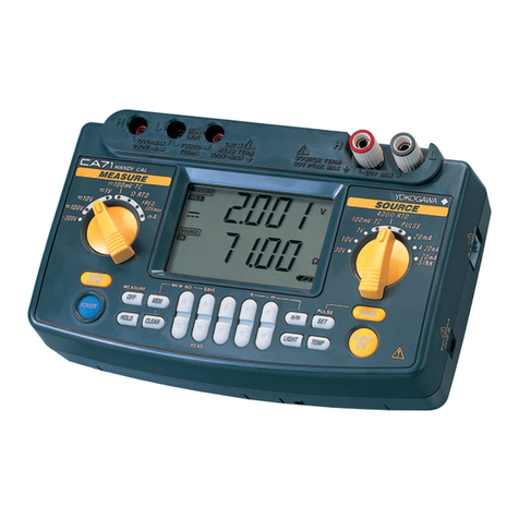
YOKOGAWA CA71 HANDY CAL User manual

YOKOGAWA

YOKOGAWA CA71 HANDY CAL User manual

YOKOGAWA 3226 User manual

YOKOGAWA

YOKOGAWA 3226 User manual

YOKOGAWA ScopeCorder DL950 User manual

YOKOGAWA

YOKOGAWA ScopeCorder DL950 User manual

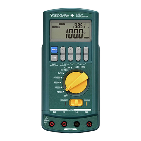
YOKOGAWA CA330 User manual

YOKOGAWA

YOKOGAWA CA330 User manual

YOKOGAWA 30032A User manual

YOKOGAWA

YOKOGAWA 30032A User manual

YOKOGAWA 30031A User manual

YOKOGAWA

YOKOGAWA 30031A User manual

YOKOGAWA 701921 User manual

YOKOGAWA

YOKOGAWA 701921 User manual

YOKOGAWA MY600 User manual

YOKOGAWA

YOKOGAWA MY600 User manual

YOKOGAWA CL255 User manual

YOKOGAWA

YOKOGAWA CL255 User manual

YOKOGAWA DLM2000 Series User manual

YOKOGAWA

YOKOGAWA DLM2000 Series User manual

YOKOGAWA DL7440 User manual

YOKOGAWA

YOKOGAWA DL7440 User manual

YOKOGAWA DLM2000 Series User manual

YOKOGAWA

YOKOGAWA DLM2000 Series User manual

YOKOGAWA CA11E User manual

YOKOGAWA

YOKOGAWA CA11E User manual

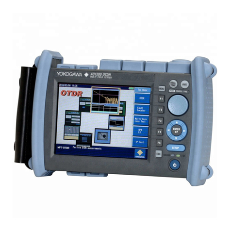
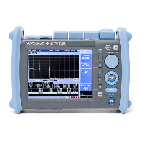
YOKOGAWA AQ1200 User manual

YOKOGAWA

YOKOGAWA AQ1200 User manual

YOKOGAWA DL7440 User manual

YOKOGAWA

YOKOGAWA DL7440 User manual

YOKOGAWA CA330 User manual

YOKOGAWA

YOKOGAWA CA330 User manual

YOKOGAWA DL1620 User manual

YOKOGAWA

YOKOGAWA DL1620 User manual

YOKOGAWA 240413 User manual

YOKOGAWA

YOKOGAWA 240413 User manual

YOKOGAWA 701985 Series User manual

YOKOGAWA

YOKOGAWA 701985 Series User manual

YOKOGAWA 30032A User manual

YOKOGAWA

YOKOGAWA 30032A User manual

YOKOGAWA CA320 User manual

YOKOGAWA

YOKOGAWA CA320 User manual

Popular Test Equipment manuals by other brands

DMC DMC95 manual

DMC

DMC DMC95 manual

Hioki 3455 instruction manual

Hioki

Hioki 3455 instruction manual

PCB Piezotronics Larson Davis CAL250 manual

PCB Piezotronics

PCB Piezotronics Larson Davis CAL250 manual

Teledyne Lecroy MS-250 Operator's manual

Teledyne Lecroy

Teledyne Lecroy MS-250 Operator's manual

Tektronix T202 Operator's manual

Tektronix

Tektronix T202 Operator's manual

ASG DTT Series PROGRAMMING AND CALIBRATION MANUAL

ASG

ASG DTT Series PROGRAMMING AND CALIBRATION MANUAL

SenTech Suracell iblow 10 user manual

SenTech

SenTech Suracell iblow 10 user manual

Elma Sagab Volt Stick Wide manual

Elma

Elma Sagab Volt Stick Wide manual

TSI Instruments 4046 user guide

TSI Instruments

TSI Instruments 4046 user guide

Vaisala AMT101 Configuration

Vaisala

Vaisala AMT101 Configuration

VOLTCRAFT DSO 4000 Series operating instructions

VOLTCRAFT

VOLTCRAFT DSO 4000 Series operating instructions

LeCroy WaveJet 300A series manual&nbsp;

LeCroy

LeCroy WaveJet 300A series manual&nbsp;

bloom ferritin Instructions for use

bloom

bloom ferritin Instructions for use

SMC Networks raptor user guide

SMC Networks

SMC Networks raptor user guide

pico Technology TA041 user guide

pico Technology

pico Technology TA041 user guide

Tetra WaterTest Set Plus manual

Tetra

Tetra WaterTest Set Plus manual

AlcoSense Zero user manual

AlcoSense

AlcoSense Zero user manual

Jula Meec Tools 405-056 User instructions

Jula

Jula Meec Tools 405-056 User instructions

manuals.online logo
manuals.online logoBrands
  • About & Mission
  • Contact us
  • Privacy Policy
  • Terms and Conditions

Copyright 2025 Manuals.Online. All Rights Reserved.