Power Probe ECT3000 User manual

powerprobetek.com | 1.800.655.3585

Contents
Congratulations ......................................................................................................................................... 4
Parts ........................................................................................................................................................... 5
The SMART Transmitter ....................................................................................................................... 6
Characteristics of the Short/Grounded Circuit Signal ............................................................................... 8
Characteristics of the Open Circuit Signal ....................................................................................... 9&10
The SMART Receiver ........................................................................................................................... 11
Battery Installation .................................................................................................................................. 12
Testing the SMART Receiver ................................................................................................................. 12
Pulse Mode .............................................................................................................................................. 12
Locking /Setting the Sensitivity of Short/Grounded Circuit Signal ....................................................... 14
Locking /Setting the Sensitivity of Open Circuits ................................................................................. 14
Direction to Short .................................................................................................................................... 15
How to Use the ECT3000 in Diagnosing Circuits .............................................................................. 16
2

Contents
How to Trace Out a Short Circuit to Chassis Ground ............................................................................. 17
Isolate your Circuit .................................................................................................................................. 18
Verify the Short Circuit to Ground .......................................................................................................... 18
Short Circuit inside a Wire Harness ........................................................................................................ 19
Reception Distance and What that Means .............................................................................................. 20
Tracing Circuits that are Shielded ........................................................................................................... 21
Open Circuit Signal vs. Grounded Circuit Signal ................................................................................... 22
How to Trace an Open Circuit ................................................................................................................ 23
Verify an Open Circuit............................................................................................................................. 23
Bench Tracing a Wire Harness ................................................................................................................ 24
Tracing Out a Battery Drain or Current Draw ........................................................................................ 25
Circuit Wiggle and Flex Test ................................................................................................................... 26
Index ........................................................................................................................................................ 27
3

Congratulations
Thank you for choosing the Power Probe “ECT3000” (Electronic Circuit Tracer- 3000)
The ECT3000 helps quickly locate wiring shorts and opens. The ECT3000 operates just like the trusted Power Probe ECT3000 now with many
improvements in functions and features to increase circuit testing accuracy and speed. This instruction booklet will give you some valuable
diagnosing tips gathered from the field and from our testing lab. This instruction booklet has convenient references that will take you to appro-
priate pages that provide more information and clarification. Taking the time to read this instruction booklet carefully will give you valuable
insight to these detailed techniques in tracing automotive circuits.
We designed the ECT3000 as a quick solution to your automotive circuit problems. The ECT3000 consists of 2 main components. An Intelli-
gent transmitter and a Intelligent receiver along with a set of connection adapters that will help you:
• Locate short circuits without unnecessarily removing plastic panels, molding, and carpet.
• Trace wires to see where they lead
• Find open circuits, switches or breaks in wires
• Trace and locate the cause of a severe battery drain
• Test and find intermittent conditions
• Check continuity with the assistance of the Power Probe III, IV, or Hook
These features are extremely handy for the professional technician. An appropriate schematic or wiring diagram is always useful and many
times necessary when tracing circuits. The better you understand your circuit, the better the ECT3000 can assist you.
4

PPTK0003
PPTK0006
PPTK0005
PPTK0007
PPTK0008

The Transmitter
The transmitter is designed to generate Grounded Circuit signals and Open Circuit signals. The grounded and the open circuit signals are very
dierent from each other, so it is very important to understand the dierences in each signal type. (see “Characteristics of the Short/Grounded
Circuit Signal” pg. 8 and Characteristics of the Open Circuit Signal” pg. 9)
Power Lead
The 20 ft. power lead of the Intelligent transmitter supplies power by connecting directly to
the vehicles battery and the long length provides easy access to circuits throughout the vehi-
cle. The RED clip connects to the positive side of the battery and the BLACK clip connects
to the negative. It can be connected to a power source from 12 to 24 volts.
Signal Lead
The signal lead with the green banana jack, plugs into the assortment of adapters, probes,
and clips that are provided for you in the ECT3000 kit. These accessories simplify connect-
ing to your circuit.
Moveable Hanger / Stand
Provides multiple convenient mounting options when testing.
Circuit Status LED indicators
Indicates current circuit staus - Short / Open.Tone On/O - Toggle Tone
“Tone On/O” button toggles the tone of the transmitter’s speaker on or o.
The toggle tone feature of the Intelligent transmitter gives you the ability to detect changes
in the circuit to detect intermittent problems. (See “Circuit Wiggle and Flex Test” pg. 26)
Speaker
Provides Audible circuit status indication.
6

After connecting the transmitter’s 20 ft. power lead to the vehicle’s battery, a signal is generated through the green signal wire and banana plug.
This is connected to the circuit you want to trace. The signal will radiate along the circuit, which you can detect by using the receiver. There are
two types of circuit signals that the transmitter generates. They are the Grounded Circuit SIGNAL and the OPEN CIRCUIT SIGNAL.
It is very important to familiarize yourself with both of these signals and how they work in your circuit. The “Grounded Circuit signal” and the
“open circuit signal” are dierent from each other, which you should understand. (See: “Characteristics of the Short/Grounded Circuit Signal”
pg.. 8 and “Characteristics of the Open Circuit Signal” pg. 9&10)
The 2 main features of the ECT3000 is that it transmits a signal into a circuit with the transmitter and then you trace it with the receiver . The
easiest way to insure that you are following the problem circuit is to isolate it from other parallel circuits.
7
Complete Circuit Signal
Open Circuit Signal

Characteristics of the Short/Grounded Circuit Signal:
1. Strongest when flowing exclusively through one wire
When the signal is conducting through only one wire, the signal
strength is at its maximum because 100% of the signal is travel-
ing through that wire exclusively to return back to the negative
side of the battery. If the signal branches out to parallel circuits,
its strength divides and of course is weaker in each branch of
the divided circuit. But when the signal recollects through the
single negative cable to return to the battery, the signal strength
is at its maximum again because 100% of the signal is concen-
trated through the single negative battery cable. (see “Isolate the
Circuit You are Tracing” pg. 18)
2. Travels the path of least resistance
In case of a short circuit that blows its fuse reliably, you can
sometimes get away with not having to isolate the circuit. The
majority of the signal will follow the path of least resistance
through the short and then back to the battery. In fig.1, you can
see the majority of the signal travels right to the short circuit.
You can also see only a small portion of the signal running
through parallel wires.
3. A 4 KHz Polarized Signal
The fact that the Grounded Circuit signal is a 4 KHz polarized signal provides directional information for the receiver to pick up. This capabili-
ty to indicate the direction to the short or ground takes the guesswork out of tracing grounded circuits. (See “Direction to the Short” pg. 15)
4. Carries a current of only 100 mA.
When generating a Short/Grounded Circuit signal, a maximum of 100 milliamp flows from the signal lead. This keeps you safe from damaging
sensitive computer circuits.
8
Path of Least Resistance
Major portion of signal goes
into short (ground)
Very small traces of signal
branch into parallel circuits
Lights have resistance
and limit signal flow

Characteristics of the Open Circuit Signal are:
1. Transmits through NON Conductive Materials
The signal that the ECT transmits when tracing open circuits, radiates
what is called an E-field. We will refer to an E-field in this manual as an
“Open Circuit Signal”.
The open circuit signal radiates from wires and passes through non con-
ductive material such as dry carpet, plastic panels or plastic molding. The
receiver is used to detect these signals so you can trace and locate the
open or break in the circuit.
(See “Locking the Sensitivity” pg. 14)
2. Easily Shielded by Conductive Materials
The open circuit signal is however easily shielded by conductive mate-
rials such as metal, wet carpet, neighboring wires in a harness and even
your hand. This means that if conductive materials are between the trans-
mitting wire and the receiver, the open circuit signal will not penetrate
through and therefore not be detected by the receiver. So it is necessary
to be aware of possible shielding issues and try to avoid them as much as
possible.
A great alternative to the receiver in detecting open circuit signals is to
use the Power Probe III, IV, or Hook by direct contact.
(see “Verify an Open Circuit” pg. 23)
9
Dry Carpet / Plastic Panels & Molding
Holding the receiver by this corner,
prevents your hand from sheilding
the
open circuitsignal.
Wet Carpet / Metal/ Shielding Wire Harness
Holding the receiver by this corner
prevents your hand from shielding
the open circuit signal.
Wet Carpet/ Metal/ Shielding Wire Harness
Dry Carpet / Plastic Panels and Mouldings
Open signal passes
through dry non
-conductive material

3. Signal Capacitive Coupling to Parallel Floating Circuits
Another characteristic of the open circuit signal is that it will capacitive couple to parallel floating circuits.
(See: “Bench Tracing a Wire Harness” pg. 24)
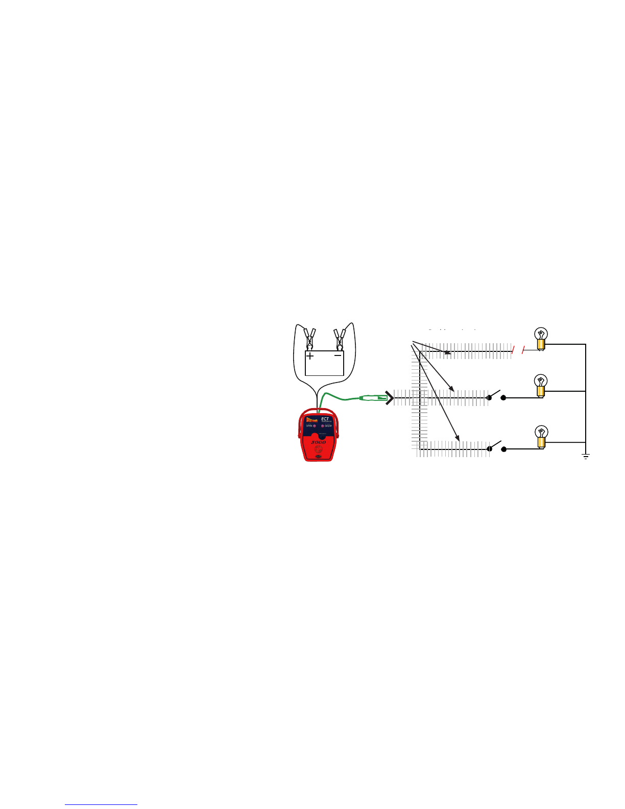
4. Travels to ALL Open Ends
In Fig. 1 we are injecting an open circuit signal into a
parallel circuit that has three wires. Two of those wires lead to
open switches and the other leads to the open/break. As you
can see the open circuit signal travels to all open ends. This
makes it necessary to isolate the problem circuit away from the
others.
5. Can only be present in a circuit when there is a resis-
tance greater than 100 ohms
(See: Open Circuit Signal vs Grounded Circuit Signal” pg. 22)
6. Has NO Polarity
The open circuit signal does not have a polarity therefore the
ECT receiver gives no direction indication as to a break in
the wire. You will need to logically reason the direction of the
break in the circuit and then continue to trace it.
7. 8 Volt amplitude and 4 kilo-Hertz signal
The 4 Kilo-Hertz signal of the open circuit signal can be de-
tected by the receiver. (See: “Locking the Sensitivity for Open
Circuits” pg. 14) You can also use the Power Probe III, or Power probe IV for open circuit signal detection by direct contact.
(See: “Verify an Open Circuit” pg. 23)
Problem circuit not
isolated
Signals are all
over the
place, because
the problem
circuit has not
been
isolated
Fig. 1
10
Signals are all
over the place,
because the
problem circuit
has not been
isolated
Problem circuit not isolated

The Receiver
The receiver is designed to detect the “Grounded Circuit signals” and the open circuit signals from the transmitter.
11
Auto shut-o feature
The receiver will automatically shut-o
within 10 minutes when it is NOT receiv-
ing a signal.
The “Open & Short Pick-Up”
located on the side of the receiver housing
is to sense and detect complete and open
circuit signals.
The “Power On/O / Sense High Button
performs three functions:
1. It turns the receiver ON and enters “pulse
mode” (see “Pulse Mode” pg. 12)
2. It increases the receiver signal sensitivity.
(greater distance range)
3. Turns o the receiver
The “Wire Harness Probe” is for probing
a harness to detect the open circuit signal.
(See “Tracing Circuits that are Shielded”
pg.21 )
The “Direction to Short/ Ground” indica-
tors point you in the direction to the short
or ground of the complete circuit. (See “Di-
rection to the Short Circuit” pg. 15)
The “Open Circuit” LED on the housing
indicates when it is receiving an open circuit
signal.
The “Sense Lock / Sense Low Button
performs two functions:
1. It locks the receiver to the Open or Shorted
circuit signal.
2. It turns receiver signal sensitivity down.
(tighter distance range)

12
Battery Installation
1. To install the batteries, carefully remove two battery covers screws, remove the battery cover on the bottom of the
receiver housing and insert (2) AAA batteries into the battery compartment. Be sure the polarity of the batteries are correct
then replace the battery cover.
Testing the SMART Receiver
To test the ECT receiver, connect the ECT transmitter to the vehicle’s battery, turn on the receiver by pressing the “Power
On/O / Sense High” button. Place the “Open & Short Pick-Up” of the receiver on top of the green signal lead. The receiv-
er should detect the open circuit signal and indicate this by the open circuit LED indicator flashing and pulsing a beeping
tone.
To test the receiver for the “Short/Grounded Circuit signal”
connect the green signal lead to the negative post of the bat-
tery. Then you can test the Grounded Circuit signal by
placing the ”Open & Short Pick-Up” of the receiver parallel to
the green signal lead. The receiver should detect the
“Grounded Circuit signal” and show the direction to ground by
the “Direction to Short or Ground” indicators.
Pulse Mode
When you first turn on the receiver it enters into “Pulse Mode”.
“Pulse Mode” is great for the initial detection of the transmit-
ting signal. You can also get a feel for the strength of
the transmitting signal.
As you place the “Open and Short Pick-Up” near a transmit-
ting signal, an LED indicator will blink repeatedly along with
an audible beep.
No signal zone
(no pulse)
Weak signal zone
(slow pulse)
Strong signal zone
(rapid pulse)

13
When the Receiver is in “pulse mode”:
1. It detects both “grounded” and “open” circuit signals.
2. It picks up and determines strong from weak signals by the pulse frequency rate.
3. The sensitivity is ready to be locked in, by pressing the “Sense Lock / Sense Low” button.
4. It detects and displays the direction to ground or a short circuit.
While in “pulse mode” and then pressing the “Sense Lock / Sense Low” button, the receiver’s sensitivity will now be locked and no longer be
in “Pulse Mode”.
The Receiver’s Reception Sensitivity:
When the receiver is in “pulse mode” you can lower it progressively closer to the transmitting signal and hear the increase in the pulse frequen-
cy as it passes each of the 8 sensitivity levels. The fastest pulse frequency is when you are nearest to the transmitting signal. Once you press
the “Sense Lock / Sense Low” button the reception sensitivity is locked into that distance (plus/minus a couple of inches) from the transmitting
circuit.
In order to lock the reception sensitivity of the receiver, two conditions must be met.
1. The receiver must be in “Pulse Mode”.
2. The receiver must be receiving a signal
When these two conditions are met, you can now press the “Sense Lock / Sense Low” button to lock the dis-
tance of the receiver and reception sensitivity.
Adjusting the receiver’s sensitivity:
Pressing either the “Sense High’ or “Sense Low” buttons on the receiver will either increase or decrease the receiver’s sensitivity distance. The
“Sense Level” LED bar graph display indicates the set sensitivity range. Eight LEDs lit means the most signal range and will pickup signals up
to approx. 8 inches. One LED lit means the least signal range, approx. 1 inch. This can be changed at any time after the intitial signal lock, and
can be used to approximate the distance from the receiver that the problem wire is. This feature can also be used to increase and decrease the
signal tolerance as you trace a circuit through a vehicle. You may have to increase range to read through a larger obstacle, while a tighter range
will allow you to follow individual wires or circuits more accurately.

14
Locking the Sensitivity for Short/Grounded Circuits
To lock the receiver’s sensitivity for short/grounded circuits, it must be turned on
and in “pulse mode”. Hold the “Open & Short Pick-Up” of the receiver parallel and
as near to the wire as you can while achieving the most rapid pulse rate. (See: Fig.
A) Now press the “Sense Lock/Sense Low button”. The receiver is now locked into
the strong “Grounded Circuit signal” and will ignore weaker parallel circuit sig-
nals. If you need to readjust the receiver’s sensitivity so that it will pick up weaker
circuit signals and be more sensitive, press the “Power On/O / Sense High” button
to return to increase sensitivity.
Locking the Sensitivity for Open Circuits
To adjust the receiver so that it is at its most sensitive setting in open circuit trac-
ing. First turn on the receiver. It is now in “pulse mode”. Hold it as close to the
open circuit as you can while receiving the most rapid pulse frequency.
Now lift the receiver about 4 inches away from the circuit and press the “Sense
Lock/Sense Low” button. (See: Fig. B) At this level you should be able to pick
up the open circuit signal in that circuit and eliminate other signals that could be
capacitive coupling into neighboring floating circuits and causing you problems.
If you need to adjust the receiver so that the reception sensitivity is more sensitive,
press the “Power On/O / Sense High” button or the “Sense Lock/Sense Low”
button to adjust sensitivity up or down. Adjust until you achieve the proper setting
for your application.
Fig. A
Fig. B
Close distance for
Short/Complete
circuits.
6” to 10” from the wire
for open circuits.

15
Direction to the Short
The Short/Grounded Circuit signal is polar-
ized. This gives the receiver the information
it needs to show you the direction to the short
or the direction to ground. When you place the
receiver’s
“Open & Short Pick-Up” parallel to the wire
of the Grounded Circuit signal, “Direction to
Short/Ground” indicator will point you in the
direction to ground. If you were to flip the
receiver in the opposite direction it will detect
the polarity change, the “Direction to Short/
Ground” indicator will flip, and it will still point
you in the direction to ground. Keep in mind
that the receiver’s “Open & Short Pick-Up”
must be held parallel to the circuit for the “Di-
rection to Short/Ground” to indicate.
The ECT3000 works equally well with either
positive chassis ground or negative chassis
ground. The only thing you need to keep
in mind is, when tracing short circuits the
receiver always points you towards the minus of
the battery so if you have a short between your wiring and the chas-
sis is a positive ground system, you just need to trace in the opposite
direction the LED is pointing!
Direction indicator shows
direction to ground or
short.
No reception
when
NOT held parallel
to circuit.
Direction indicators show
direction to ground or short
No reception when
NOT held parallel to the
circuit.
Direction indicators show
direction to ground or short

16
How to Use the in Diagnosing Circuits
Connection Accessories:
Included in the ECT3000 are the following connection accessories.
• Alligator Clip: for connecting onto any conductor such as a wire or a terminal.
• Blade Probe: for tapping into fuse socket terminals and connectors.
• Back Probe: for back probing connectors.
• Piercing Probe: for tapping into wires by piercing through the insulation.
• Light Bulb Socket Adapters: 3 common types for connecting easily to light bulb socket
terminals. There are times when the short or open tail or brake light circuit is located nearer to the
bulb socket. It is here where you may find it much easier to diagnose the circuit by injecting a signal
into the light socket directly.
• Universal Wire Adapter: for making your own custom connector.
Fig.1 There are times when a short or open circuit is located
closer to the tail light or brake light circuit. It is here where you
may find it much easier to diagnose the circuit by injecting a
signal into the light socket directly. The bulb socket adapters
provide a quick and easy way to connect to bulb socket termi-
nals.
Fig.2 Other times it maybe necessary to inject the signal at the
fuse panel using the flat blade adapter.
Fig.3 Using the alligator clip adapter on an already exposed
wire or the piercing probe are other options.
igator
p to
ect
the
nal
Using
Blade
Probe
in fuse
terminal
All
Cli
inj
sig
#AA1
#AA2
e
#PNECT057

17
How to Trace Out a Short Circuit to Chassis Ground
A direct short to chassis ground that blows a fuse, is one of the simplest circuits to trace for one simple reason. The majority of the “Grounded
Circuit Signal” travels THROUGH THE SHORT CIRCUIT TO CHASSIS GROUND making it easy to trace. This sometimes eliminates the
need for isolating the circuit.
1. Remove the blown fuse
2. Connect the transmitter’s “power lead” to the vehicles battery
3. Connect the “signal lead” to the shorted terminal of the fuse panel using the Blade probe.
4. Turn on the receiver. It will be in “pulse mode”.
5. Place the “Open & Short Pick-Up” about 2” from the wire harness and parallel to the shorted wire until the “Direction to Short or
Ground” indicator beeps rapidly.
6. Press the “Sense Lock/Sense Low” button.
7. Trace the circuit in the direction of the indicator until you loose the signal.
8. If you reach an obstacle remove it or work through it. Remember to ISOLATE THE CIRCUIT YOU ARE TRACING. Inspect the
circuit and verify the short. (See: “Verify a short circuit to ground” pg. 18)
9. Isolate the short circuit you are tracing and reconnect the “signal lead directly to the new found part of the shorted wire. (See: “Isolate
the Circuit you are Tracing” pg. 18)
10. Continue to follow the signal until you loose it.
11. Inspect the circuit and verify the short.
12. Repeat steps 7 through 10 until you find the cause of the short circuit.
13. Once you fix the short, reconnect all the sections of the circuit you had disconnected earlier.

18
Isolate the Circuit You are Tracing
Isolating the circuit you want to trace is absolutely necessary when using “Open
Circuit Signals”. It is always good to disconnect the circuit you are tracing
away from other parallel circuits. Once you isolate the troubled circuit, you can
then connect the transmitter’s signal lead exclusively to your selected circuit.
Connecting exclusively to your ISOLATED circuit insures that the SIGNAL
is confined in just that one single circuit. The signal strength remains constant
throughout the isolated circuit. This makes the circuit easier to trace. You also
eliminate confusion of the signal branching o to other areas that will lead you
astray. When you are finished diagnosing, don’t forget to reconnect the isolated
circuit.
Isolating a short/grounded circuit is best done by removing the loads in the cir-
cuit. This accomplishes two things: 1. It assures that 100% of the signal is being
transmitted down the wire you are tracing, 2. if the circuit goes intermittent, the
transmitter will alert you. (See: “Circuit Wiggle & Flex Test” pg. 26
Verify a Short Circuit to Ground
One of the best tools for verifying a short circuit to ground is the Power Probe 1,
2, or 3. To verify a short circuit connect the Power Probe to the circuit and press
the power switch forward. If the Power Probe’s circuit breaker trips, you have
verified the short.
IMPORTANT
Be careful not to power up circuits that are connected to the vehicles onboard
computer. You may have to unplug the computer or electronic modules when
performing short circuit verication on electronic systems.
Signals are
Problem circuit not
isolated
all over
the
place,
because
the
problem
circuit has not
been isolated
Fig. 1
Signals are all
over the place,
because the
problem circuit
has not been
isolated
Problem circuit not isolated
Signal injected
direct into problem
circuit
Disconnected from circuit
These circuits are no longer a
problem because they are discon-
nected from the problem circuit.

19
Short Circuit Inside a Wire Harness
A common occurrence inside of wiring harnesses is that there are two wires running close and parallel to each other. One wire is the positive
wire that flows one way and the ground wire that flows back the opposite direction. When the signal source runs closely parallel to the signal
return, as in this case, they cancel each other and the signal strength is considerably reduced.
You can pull one wire at a time away from the other wires, creating some distance between them. As you hold the wire away from the other
wires, the signal canceling eect is removed in that area and the signal strength will increase in the wire. You can now get a reading o of the
wire with the receiver by holding it parallel to the receiver’s pick-up area. Take note of the directional indicator of the receiver. Check for the
other wire that indicates the opposite direction. You can now assume that both wires are in the same circuit. Trace both wires as a pair along
the harness until you find the problem. (see illustration)

20
Reception Distance and What that Means.
When tracing parallel circuits, you can determine if a one wire has a stronger “Ground-
ed Circuit signal” present over another wire. The wire that has a stronger signal carries a
larger current. This means the circuit that has the stronger signal also has a lower resistance
compared to the other parallel branch. Just knowing this information can come in handy
when determining the fault of a circuit.
Once the receiver is locked into the Short/Grounded Circuit signal, (see “Locking the sen-
sitivity of short/grounded circuits”) note the distance of the pick-up area to the wire as you
slowly lower it down near to the wire. For exam-
ple, you will notice the receiver’s indicator comes
on about 2 inches with one wire and 3 inches with
the other wire. The wire that makes the receiver
come on 3 inches away is transmitting a stronger
signal than the circuit that makes the receiver come
on only 2 inches away.
That’s important to know so you can understand
and determine which wire has a stronger signal.
This is why it is always recommended to isolate
your troubled circuit. Isolating your circuit insures
that you are following the correct circuit and it
avoids confusion with other parallel wires or
circuits.
(See “Isolating the Circuit”pg. 18)
Table of contents
Other Power Probe Test Equipment manuals