FLI UNDERGROUND FU1000.5 Parts list manual

UNDERGROUND
INSTRUCTION &
INSTALLATION MANUAL
MODEL: FU1000.5
AMPLIFIER
1000.5

INTRODUCTION
This instruction manual is for your safety and must be adhered to at all times. Please read
and ensure that you fully understand the installation and set up procedures as explained.
If you are unclear on the installation or set up of your FLI UNDERGROUND amplifier please
contact your nearest authorised FLI UNDERGROUND dealer.
Thank you for purchasing this FLI UNDERGROUND amplifier. It will provide you
with years of trouble free usage providing you follow a few simple guidelines.
2
WARNING
DO NOT EXPOSE THIS PRODUCT TO DAMP OR MOISTURE - doing so may result in fire,
shock or damage to the product.
BEFORE WIRING DISCONNECT THE CABLE FROM THE POSITIVE BATTERY TERMINAL
- failure to do so may result in electric shock or injury.
ENSURE GOOD AND CORRECT CONNECTIONS - failure to make the correct connections
may result in fire or damage to the product.
KEEP THE VOLUME AT A LEVEL SO YOU CAN STILL HEAR OUTSIDE NOISE - failure to
do this may result in an accident. FLI equipment is capable of producing sound levels that can
permanently damage your hearing. FLI recommends caution when listening at high volume. For
safe and enjoyable listening the sound should be comfortable and clear without distortion.
CAUTION
• Never connect any speaker lead to the car chassis. This can cause severe damage to your
speaker / car radio / amplifier.
• Before drilling or cutting any holes, investigate the layout of your vehicle thoroughly.
• Use caution when working near the fuel / hydraulic lines and electrical wiring.
• Observe the correct polarity when wiring, improper phasing may cause a loss of bass
response.
• Ensure that no moving parts catch on the speaker or grill (e.g. window or door handles, or
window glass inside the door)
INSTALLATION
• The quality of the installation will affect the system performance and reliability.
• Contact your nearest authorised FLI dealer if you are unsure about the installation of this
product.
• Please mount this unit away from any potential hazards.
• Minimising the length of wires will provide higher audio output from the system.
• The speaker should be securely fastened to the mounting position using the screws
provided.
• Pre drill your mounting holes using a drill and position with the template provided.
• Be sure to investigate your mounting area thoroughly for electrical wires, brake or fuel lines or
fuel tank to prevent causing any damage.
BLE F
ock or injur
ONNECTIONS
-
roduct.
EL SO YOU CAN STILL
t. FLI equipment is capable o
ring. FLI recommends caution w
he sound should be comfortable an
peaker lead to the car chassis. This can cause
/ amplifie
utting any holes, investigate the layout of your vehicle
n working near the fuel / hydraulic lines and electrical wi
correct polarity when wiring, improper phasing may cau
no moving parts catch on the speaker or grill (e.g. window or d
ass insid
ALLAT
quality of the installation will affect the system performance and reliability.
ntact your nearest authorised FLI dealer if you are unsure about the installation
oduct.
Please mount this unit away from any potential hazards.
Minimising the length of wires will provide higher audio output from the system.
the system
ealer if yo
ipment is
commends
ould be co
car chas
stigate th
/ hydrau
ring, im
e spe

3
AMplifier Installation
Your FLI UNDERGROUND amplifier is designed with a swift installation routine in
mind. Please mount the amplifier in a dry location on a solid surface. NEVER mount the
amplifier upside down, this will cause the amplifier to over heat and will eventually damage
the amplifier. Before fixing the amplifier in place please ensure that there is sufficient air
flow around the exterior of the casing, at least two inches will be sufficient.
Power Cable
• At least an 8 gauge cable should be used for both the power and the ground connections to
the amplifier.
• The power cable should be taken directly from the battery. Rubber grommets should be used
when passing through any bulkheads to prevent the cable from becoming chaffed or cut.
• It is vital that a fuse / circuit breaker (of at least equal value to the one fitted on the amplifier) is placed
in line with the power cable and is no further than eighteen inches away from the battery.
• Please ensure that the fuse is not fitted until the entire installation procedure is complete.
• The two tables below are to help you decide on what cable is correct for you. The first enables you to
select the size of cable depending on the length required. The second will help you convert the cable
size from American Wire Gauge to Metric if you need to.
L
en
g
t
h
of
Run
Cu
rr
e
n
t
de
m
an
d
0
–
4
F
t
4
–
7
F
t
7
–
1
0
F
t
1
0
–
1
3
F
t
1
3
–
1
6
F
t
1
6
–
1
9
F
t
1
9
–
22
F
t
22
–
2
8
Ft
0
–20
amp
s
14
1
2
1
2
1
0
1
0
8
8
8
20
–
35
am
p
s
1
2
1
0
8
8
6
6
6
4
35
–
50
am
p
s
1
0
8
8
6
4
4
4
4
50
–
65
amp
s
8
8
6
4
4
4
4
2
65
–
85
amp
s
6
6
4
4
2
2
2
0
8
5–10
5
amp
s
6
6
4
2
2
2
2
0
105
–
125
a
mp
s
4 4 4
2
0
0
0
0
12
5
–1
50
amp
s
2
2
2
0
0
0
0
0
A
WG
AA
t
o
Me
tr
ic
C
onversio
n
C
har
t
cross
sec
ti
o
n
a
l
area
A
WG
AA
Nu
m
be
r
I
n
c
h
m
m
mm
2
0
0
.
3
2
5
8
.25
53
.
5
1
0
.2
89
7.
35
42.4
2
0
.2
58
6
.
54
33
.
6
3
0
.22
9
5
.8
3
26.
7
4
0
.2
04
5
.1
9
21.1
5
0
.1
82
4.
62
1
6
.
8
6
0
.
162
4
.
1
1
13
.
3
7
0
.14
4
3
.
66
1
0
.
5
8
0
.12
8
3
.2
6
8
.
36
9
0
.
1
14
2
.
91
6
.
63
1
0
0
.10
2
2.5
9
5
.26
1M
e
tr
e
–
3
.2
8
F
ee
t

4
ground cable
• The ground cable needs to carry the same current as the power cable. At least an 8
gauge cable should be used.
• The amplifier ground should be connected directly to the chassis of the vehicle, to bare
metal.
• The cable length should be kept to an absolute minimum. It is not recommended that you
connect the ground cable to the vehicle’s seatbelt anchor point.
Remote Turn On
• A minimum of 18 gauge cable should be used for this connection.
• The cable should be run with exactly the same care and attention as the power cable and taken
back to the source (headunit) and joined to the remote cable provided.
• If the source (headunit) does not have a remote turn on cable then a 12v supply should be used. This
will require a switch to be fitted inline to enable the amplifier to be turned on and off. Remember that if
this switch is left on you will flatten the car battery.
RCA Cables
• Depending on the model number of your amplifier and the number of speakers you wish to power you will
have to run either one or two RCA cables from the source to the amplifier.
• Please take extra care when running these cables from the source to the amplifier. Ensure that they are
placed away from all items that can generate any interference, wiring harnesses etc.
• It is recommended that the RCA cables should be run on the opposite site of the car to the previously
installed power cables, if possible.
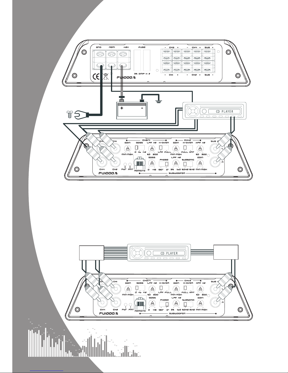
AMPLIFIER CONNECTIONS & CONTROLS
A. LOW LEVEL INPUT
Low level input for connection to any source (headunit) with a low level stereo output. This is your
RCA output from the source (headunit).
B. GAIN CONTROL
Used to match the input signal of the source (headunit) to the amplifier. There are separate
controls for channels (1 & 2), (3 & 4) and subwoofer. See the setup section for more
details.
L K
A
B
E
M
J IN HAB
B
C CF D
G

5
C. CROSS OVER SELECT SWITCH (STEREO CHANNELS ONLY)
Used to select between high pass filter and full range output (channel 1 & 2) or low
pass filter and full range output (channels 3 & 4). The high pass filter will only allow high
frequency information to be passed to the speaker(s) whilst the full range output will pass
all frequencies to the speaker(s). Similarly the low pass filter will only allow low frequency
information to be passed to the speaker(s).
D. CROSS OVER FREQUENCY CONTROL
The HPF control specifies which frequencies above the set level will be heard (channel 1 & 2).
The LPF control specifies which frequencies below the set level will be heard (channel 3 & 4). The
frequency ranges from 50 Hz to 300 Hz.
E. SUBSONIC CROSSOVER SWITCH
When set to 50 Hz frequencies between 50 Hz and 300 Hz will be output. When set to 15Hz,
frequencies between 15 Hz and 300 Hz will be output.
F. BASS BOOST CONTROL (CHANNELS 3 & 4 ONLY)
To provide up to an extra +12 dB of bass boost at 45 Hz. Use this boost to increase bass output from
the amplifier.
G. BASS BOOST CONTROL (SUBWOOFER ONLY)
To provide up to an extra +18 dB of bass boost at 45 Hz. Use this boost to increase bass output from the
amplifier to the subwoofer.
H. PHASE SELECT SWITCH
Use this to invert speaker output 180°, default is 0°. One setting will make the bass from the subwoofer
sound better matched with the front speakers.
I. BASS REMOTE INPUT JACK
Use to plug in the remote bass controller.
J. BASS REMOTE CONTROLLER
This remote can be mounted in the front of the car and will give you the ability to adjust the gain of the amplifier
remotely.
K. SPEAKER TERMINAL OUTPUT
For connection to the speakers. See system wiring overleaf for wiring examples.
L. FUSE
Please ensure the following fuse rating is used when replacing fuses:
FLI UNDERGROUND 1000.5 (35 amp x 2)
M. POWER CONNECTIONS
Power connections. See overleaf for details on correct connections.
N. POWER PROTECT LIGHT
When the amplifier is operating correctly the light will illuminate constant ‘green’. When the amplifier is in power
protecttion mode the light will illuminate ‘red’.
Set Up Section
To correctly set the gain control of the amplifier to match that of the source (headunit) use the following setup
routine:
• Turn the gain control to minimum on the amplifier.
• Ensure the bass boost is set to 0 dB.
• On the headunit set all crossovers to flat and both bass and treble to zero.
• Turn up the source (headunit) to approx 3/4 volume.
• Very slowly turn up the gain on the amplifier until distortion can be heard in any of the speakers or until
the volume reaches an uncomfortable listening level when this is reached turn down the gain control
slightly.
• The gain control is now set.
The setting of the crossover will depend on what kind of speaker you are installing. For a subwoofer
it is recommended that the crossover is set to low pass and the frequency is set to match that of
the speaker specifications. For a pair of full range speakers it is recommend that the crossover is
set to full. For a pair of speakers with a passive crossover it is recommended that the crossover
is set to high pass and the frequency is set to match that of the speaker specifications.
NOTE: BY USING THE CROSSOVERS CORRECTLY YOU WILL NOT ONLY
LENGTHEN THE LIFE OF YOUR SPEAKERS BUT WILL ALSO GET BETTER
PERFORMANCE FROM THEM. TO OPTIMISE YOUR SETUP SEEK THE ADVISE
OF A PROFESSIONAL INSTALLATION ENGINEER OR VISIT YOUR LOCAL FLI
AUDIO DEALER.
6
System Wiring
Input connections
High level input
When using a high level speaker input, use the supplied high to low level converter loom.
BATTERY
FUSE
Connect to
chassis / ground
of vehicle
Connect to remote turn-on
lead of source unit
SOURCE
(HEAD UNIT)
SOURCE (HEAD UNIT)
High to
Low Level
converter
High to
Low Level
converter
L+ WHITE
L- WHITE/BLACK
R+ GREY
R- GREY/BLACK
L+ WHITE
L- WHITE/BLACK
R+ GREY
R- GREY/BLACK
RL+ GREEN
RL- GREEN/BLACK
RR+ PURPLE
RR- PURPLE/BLACK

7
System Wiring
4 channel (stereo)
+ single Channel (mono)
MIN. 2Ω
MIN. 2Ω
MIN. 4Ω
+
-+
-
+
-
+
-
+
-

8
Troubleshooting
Before removing the amplifier, refer to the list below and follow the suggested
procedure. Always test the speakers and confirm that they are wired correctly first. If in
any doubt get help from a qualified auto electrician.
AMPLIFIER WILL NOT POWER UP
• Check for good ground connections. Ensure that the ground cable is connected directly to
bare metal and not a painted surface.
• Using a multimeter check the that remote terminal has at least 7V DC.
• Using a multimeter check that there is battery voltage on the positive terminal.
• Check all fuses.
• Check that the protection light is not illuminated. If it is lit, shut off the amplifier for thirty seconds
and then turn it back on.
PROTECTION LED ILLUMINATES WHEN AMPLIFIER IS POWERED UP
• Check for shorts on all speakers wires. (i.e no speaker wires should be joined together and no speaker
wires should be touching the car’s chassis)
• The amplifier is designed to shut down automatically when the units temperature goes above 80 degrees.
If the amplifier feels very hot then this may be the reason for the amplifier not starting.
• Remove the speaker wires and reset the amplifier. If the Protection LED still comes on then the amplifier is
faulty. This damage may have been caused by either failure to follow these setup guidelines or abuse.
AMPLIFIER GETS VERY HOT
• Check the minimum speaker impedance for the amplifier is correct. See page 7 for minimum impedance
loads for this amplifier.
• Check for shorts on all speakers wires. (i.e no speaker wires should be joined together and no speaker wires
should be touching the car’s chassis)
• Check that there is good airflow around the amplifier. In some applications an external fan may be required.
BLOWN FUSE(S)
• Check both positive supply and ground for shorts.
• Check that the positive wire is connected to the positive terminal on the amplifier.
• Check that the negative wire is connected to the ground terminal on the amplifier.
• Ensure that the correct rated fuse is fitted:
FLI UNDERGROUND 1000.5 (35 amp x 2)
DISTORTED SOUND
• Check the gain control is not set at too high a level. If the speakers sound distorted turn the down the gain
until the sound is clear.
• Check that all crossover frequencies are correct. See Setup section for more details.
• Check for shorts on all speaker wires.
• Check all speakers are wired correctly. With the correct polarity being observed on each connection.

9
notes
10
specifications
KEEP IT SAFE
Staple your receipt here:
MODEL NUMBER:
SERIAL NUMBER:
PURCHASED FROM:
DATE OF PURCHASE:
In order to protect your purchase and aid your warranty please fill
in the following form and keep it safe for your future reference.
For more information and to register your warranty online, visit:
www.fliaudio.com/warranty
2
Model FU360.2 FU720.4 FU1000 .1 FU1000.5
Type 2/1 channel 4/3/2 channel monoblock
5/4/3 channel
Class AB AB D AB
4 ohm stereo 2 x 70 watts RMS 4 x 70 watts RMS N/A 4 x 70 watts RMS
2 ohm stereo 2 x 90 watts RMS 4 x 90 watts RMS N/A 4 x 90 watts RMS
4 ohm mono 1 x 180 watts RMS x 180 watts RMS 1 x 300 watts RMS 1 x 140 watts RMS
2 ohm mono N/A N/A 1 x 500 watts RMS N/A
Max power 360 watts 720 watts 1000 watts 1000 watts
Frequency response 20Hz – 20kHz 20Hz – 300Hz 10Hz - 5000Hz 20Hz - 20kHz
Height 1.9” (49mm) 1.9” (49mm) 1.9” (49mm) 1.9” (49mm)
Width 10.8” (254mm) 14” (334mm) 14” (355mm) 19.9” (505mm)
Depth 7.6” (197mm) 7.6” (197mm) 7.6” (197mm) 7.6” (197mm)

LIMITED WARRANTY
All FLI goods are covered by a full 12 months manufacturers warranty. Valid
from the date of the original receipt and proof of purchase. In order to validate
this warranty, the warranty card should be returned to FLI within seven days
of the original purchase date. The original receipt and packaging should also
be kept for this 12 month period.
If at any stage during the warranty period you have a problem with the product
then it should be returned to the point of purchase in its original packaging,
complete and with no items missing. If the store is unable to fix the product it
may have to be returned to FLI this process takes around 7 working days.
A full description of FLI’s warranty information can be found on our website:
www.fliaudio.co.uk/warranty
A written version can also be obtained from:
FLI warranty department
PO Box 11000
B75 7WG
UK
COPYRIGHT
All content included in this manual such as text, graphics, logos, icons, images data, the selection
and arrangement thereof, are the property of FLI Audio (herein referred to as “FLI”, “us” or “we”)
and its affiliate or their content and technology providers, and are protected by United Kingdom
and International copyright laws. All rights reserved.
TRADEMARKS
FLI UNDERGROUND™, FU™, UNDERGROUND™ and all stylised representations of product
names, or the abbreviations of product names, as logos are all trademarks of FLI. Graphics and
logos are trademarks or trade dress of FLI Audio or its subsidiaries. FLI’s trademarks and trade
dress may not be used in connection with any product or service that is not FLI’s, in any manner
that is likely to cause confusion among customers or in any manner that disparages or discredits
FLI. All other trademarks not owned by FLI or its subsidiaries that appear in this manual are the
property of their respective owners, who may or may not be affiliated with, connected to, or
sponsored by FLI or its subsidiaries.
We reserve the right to make needed changes or improvements to the product
and this manual, without informing the customer about this in advance.
11
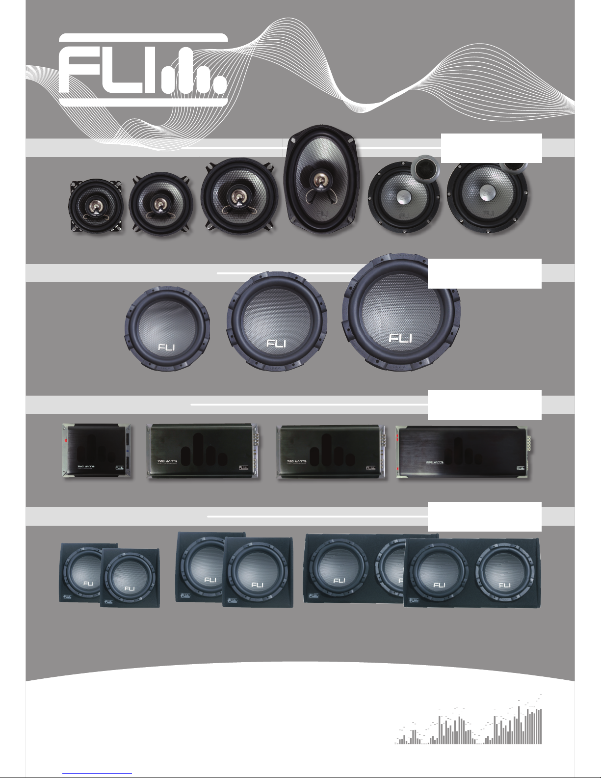
AVAILABLE NOW IN THE
FLI UNDERGROUND RANGE:
UNDERGROUND
www.fliaudio.com
up to
up to
270 watts
270 watts
speakers
FU 4 FU 5 FU 6 FU 69 FU 5c FU 6c
FU 10 FU 12 FU 15
FU 360 FU 720 FU 1000.1 FU 1000.5
FU 10P
FU 10A
FU 12P
FU 12A
FU 12TP
FU 12TA
up to
up to
1200 watts
1200 watts
up to
up to
1000 watts
1000 watts
up to
up to
2000 watts
2000 watts
subwoofers
AMPLIFIERS
ENCLOSURES
Table of contents
Other FLI Amplifier manuals


