FLIGHT LINE FL-760 series User manual

Page 0
FL
FLFL
FL-
--
-760
760760
760
VHF
VHFVHF
VHF
Aircraft
AircraftAircraft
Aircraft
Transceiver
TransceiverTransceiver
Transceiver
Installation / Operation
Installation / OperationInstallation / Operation
Installation / Operations Manual
s Manuals Manual
s Manual
FL
FLFL
FL-
--
-760 series
760 series760 series
760 series
Flig tline
Flig tlineFlig tline
Flig tline
12830 E. Mirabeau Parkway
12830 E. Mirabeau Parkway 12830 E. Mirabeau Parkway
12830 E. Mirabeau Parkway
Spokane Valley, WA 99216
Spokane Valley, WA 99216Spokane Valley, WA 99216
Spokane Valley, WA 99216
Toll free
Toll freeToll free
Toll free tel.
tel. tel.
tel.: 1
: 1: 1
: 1-
--
-800
800800
800-
--
-235
235235
235-
--
-3300
33003300
3300
Toll free fax
Toll free faxToll free fax
Toll free fax: 1
: 1: 1
: 1-
--
-800
800800
800-
--
-828
828828
828-
--
-0623
06230623
0623
ttp://
ttp:// ttp://
ttp:// www.edmo.com
www.edmo.comwww.edmo.com
www.edmo.com
VHF AM Aircraft R
VHF AM Aircraft RVHF AM Aircraft R
VHF AM Aircraft Ra
aa
adio
diodio
dio
FCC ID:
FCC ID: FCC ID:
FCC ID: VOSFL760 A
VOSFL760 AVOSFL760 A
VOSFL760 A

Page 1
ATTENTION
ATTENTION ATTENTION
ATTENTION
READ ME FIRST
READ ME FIRSTREAD ME FIRST
READ ME FIRST
FCC WARNING
FCC WARNING FCC WARNING
FCC WARNING
C anges or modifications not expressly approved by t e party responsible for compliance could void t e
user’s aut ority to operate t e equipment.
NOTICE
T is equipment as been tested and found to comply wit t e limits for a Class A digital device,
pursuant to part 15 of t e FCC Rules. T ese limits are designed to provide reasonable protection
against armful interference w en t e equipment is operated in a commercial environment.
T is equipment generates, uses and can radiate radio frequency energy and, if not installed and used
in accordance wit t e instructions, may cause armful interference to radio communications.
Operation of t is equipment in a residential area is likely to cause armful interference in w ic case
t e user will be required to correct t e interference at is own expense.
Properly s ielded a grounded cables and connectors must be used for connection to ost computer and /
or perip erals in order to meet FCC emission limits.
(AC adaptor) wit ferrite core must be used for RF interference suppression.
T e Flig t
T e Flig tT e Flig t
T e Flig tline transceiver as been factory preset and in most cases t e transmitted audio s ould
line transceiver as been factory preset and in most cases t e transmitted audio s ouldline transceiver as been factory preset and in most cases t e transmitted audio s ould
line transceiver as been factory preset and in most cases t e transmitted audio s ould
be correct. A 15 pin connector is supplied for connection to t e electrical sy
be correct. A 15 pin connector is supplied for connection to t e electrical sybe correct. A 15 pin connector is supplied for connection to t e electrical sy
be correct. A 15 pin connector is supplied for connection to t e electrical system and
stem andstem and
stem and
microp one/speaker.
microp one/speaker.microp one/speaker.
microp one/speaker.
Notes
NotesNotes
Notes to t e installer / user.
to t e installer / user. to t e installer / user.
to t e installer / user.
・ T is is a 14-volt or 28-volt DC radio, voltages greater t an 33 volts DC or AC voltage will
severely damage it.
・ W en making adjustments to t e transmitter, ensure t at you are not on an occupied c annel.
・ Do not transmit on 121.500MHz, as t is is t e international distress frequency.
・ Do not transmit into an unterminated antenna line as a suitable antenna must be connected.
Transmitting wit out being connected to an antenna may damage t e radio.
・ Ensure t at t e supply voltage is regulated and does not fall below 11.7 volts DC or exceed 31
volts DC.
・ T e transceiver is not waterproof. Do not allow it to get wet.
・ Speaker impedance must be eit er 4 or 8 o ms (4 o ms preferred) at 5 watts.
・ Use of electret microp ones ig ly recommended.
About t is document.
Due to our policy of continuous improvement to our products and services, tec nical specifications
and claims are correct at time of going to printing, owever t ey are subject to c ange wit out
notice.
Flig tline does not accept liability for any error or omission.
T is manual remains t e copyrig t of Flig tline.

Page 2
TABLE OF CONTENTS
TABLE OF CONTENTSTABLE OF CONTENTS
TABLE OF CONTENTS
SECTION Page
ATTENTION
ATTENTIONATTENTION
ATTENTION-
--
-
READ ME FIRST
READ ME FIRST READ ME FIRST
READ ME FIRST ………………………
………………………………………………
…………………………………………………
……………………………………………………
………………………….
..
.1
11
1
TABLE OF CONTENTS
TABLE OF CONTENTSTABLE OF CONTENTS
TABLE OF CONTENTS …………………………… ………………………………
…………………………………………………………………………………………………………………………
……………………………………………………………2
22
2
1 INTRODUCTION
1 INTRODUCTION1 INTRODUCTION
1 INTRODUCTION
………………………………………………………………
………………………………………………………………………………………………………………………………
……………………………………………………………….. 3
.. 3.. 3
.. 3
2 INST
2 INST2 INST
2 INSTA
AA
ALLATION INSTRUCTIONS
LLATION INSTRUCTIONSLLATION INSTRUCTIONS
LLATION INSTRUCTIONS
……………………………………………
…………………………………………………………………………………………
……………………………………………. 3
. 3. 3
. 3
3 INST
3 INST3 INST
3 INSTA
AA
ALLATION CONSIDERATIONS
LLATION CONSIDERATIONSLLATION CONSIDERATIONS
LLATION CONSIDERATIONS
…………………………………………
……………………………………………………………………………………
………………………………………….3
.3.3
.3
4 GENERAL
4 GENERAL4 GENERAL
4 GENERAL
…………………………………………………………………………
……………………………………………… ……………………… ………………………………………………… ……………………… …
……………………………………………… ……………………… ….4
.4.4
.4
4.1 Sailplanes
4.1 Sailplanes 4.1 Sailplanes
4.1 Sailplanes
…
……
………………………………………………………………………………………
…………………………………………………………………………………………………………………………………………………………………………
……………………………………………………………………………………
4
44
4
4.2 Ultralig t
4.2 Ultralig t4.2 Ultralig t
4.2 Ultralig ts
ss
s
…
……
….
. .
.
………
………………
…………………………………………………………………………………
……………………………………………………………………………………………………………………………………………………
…………………………………………………………………………
4
44
4
4.3
4.34.3
4.3 Microlig t / Homebuilt / G.A.
Microlig t / Homebuilt / G.A. Microlig t / Homebuilt / G.A.
Microlig t / Homebuilt / G.A. ……………………………………………………
…………………………………………………………………………………………………………
……………………………………………………..
....
..4
44
4
5 BEFORE BEGINNING
5 BEFORE BEGINNING5 BEFORE BEGINNING
5 BEFORE BEGINNING INST
INST INST
INSTA
AA
ALLATION
LLATIONLLATION
LLATION………………………………………
………………………………………………………………………………
………………………………………..
....
..…
……
….
..
.……
…………
……5
55
5
5.1 Installation parts
5.1 Installation parts 5.1 Installation parts
5.1 Installation parts identification..
identification..identification..
identification..………………………
………………………………………………
………………………..
....
..…
……
…………………………
………………………………………………
………………………....
........
....5
55
5
5.2 Transceiver installation and removal
5.2 Transceiver installation and removal5.2 Transceiver installation and removal
5.2 Transceiver installation and removal
……
…………
……..
....
..………………………………………
………………………………………………………………………………
………………………………………...
......
...
5
55
5
5.3
5.3 5.3
5.3 General
GeneralGeneral
General..
....
..……………………………………………………………………………
…………………………………………………………………………………………………………………………………………………………
……………………………………………………………………………..
....
..……
…………
……5
55
5
5.4 Pin connections
5.4 Pin connections5.4 Pin connections
5.4 Pin connections ...
... ...
...……………………………………………………………
…………………………………………………………………………………………………………………………
…………………………………………………………….
..
.…………
……………………
………….
. .
. 5
55
5
5.5 Mec anical installation
5.5 Mec anical installation5.5 Mec anical installation
5.5 Mec anical installation ...
... ...
...……………………………………………………………
…………………………………………………………………………………………………………………………
…………………………………………………………….
..
.…
……
…5
55
5
5.6
5.6 5.6
5.6 El
ElEl
Electrical installation
ectrical installationectrical installation
ectrical installation
……………………………………………………………………
…………………………………………………………………………………………………………………………………………
……………………………………………………………………6
66
6
5.7 Antenna
5.7 Antenna5.7 Antenna
5.7 Antenna
i
ii
installation..
nstallation.. nstallation..
nstallation..
………..............................................................
………..............................................................………..............................................................
………..........................................................................................
........................................................
............................
7
77
7
5.
5.5.
5.8
88
8
Tuning
Tuning Tuning
Tuning ………………………………………………………………………………………………
………………………………………………………………………………………………………………………………………………………………………………………………
……………………………………………………………………………………………….
..
.
7
77
7
5.
5.5.
5.9
99
9
On air testing
On air testing On air testing
On air testing …………………………………
……………………………………………………………………
………………………………………………………………………………………
…………………………………………………………………………………………………………
……………………………………………………
7
77
7
6 OPERATION OF EQUIPMENT
6 OPERATION OF EQUIPMENT6 OPERATION OF EQUIPMENT
6 OPERATION OF EQUIPMENT
……………………………………………………………
…………………………………………………………………………………………………………………………
……………………………………………………………8
88
8
6.1 General
6.1 General6.1 General
6.1 General
…………………………………………………………………………………
……………………………………………………………………………………………………………………………………………………………………
…………………………………………………………………………………..
....
.....8
...8...8
...8
6.2 Control d
6.2 Control d6.2 Control d
6.2 Control description
escriptionescription
escription
…………………………………………………………………
……………………………………………………………………………………………………………………………………
…………………………………………………………………..
....
..…
……
…8
88
8
6.3 Memory programming
6.3 Memory programming6.3 Memory programming
6.3 Memory programming
……………………………………
…………………………………………………………………………
………………………………………
……
…………………………
………………………………………………
…………………………
……
…10
1010
10
6.4 Memory delete
6.4 Memory delete6.4 Memory delete
6.4 Memory delete
……………………………
…………………………………………………………
…………………………………………………………………………
…………………………………………………………………………………………
……………………………………………. 10
. 10. 10
. 10
6.5 Operation of intercom
6.5 Operation of intercom6.5 Operation of intercom
6.5 Operation of intercom
……………………………………………………………
…………………………………………………………………………………………………………………………
……………………………………………………………. 10
. 10. 10
. 10
6.6 User setting
6.6 User setting6.6 User setting
6.6 User setting
…………………………………………………………………………
……………………………………………………………………………………………………………………………………………………
…………………………………………………………………………. 10
. 10. 10
. 10
6.7
6.7 6.7
6.7 Music
MusicMusic
Music input
input input
input ……
…………
……
……………………………………………………………………
…………………………………………………………………………………………………………………………………………
………………………………………………………………………
……
…..
....
..
1
11
11
11
1
7 SPECIFICATIONS
7 SPECIFICATIONS7 SPECIFICATIONS
7 SPECIFICATIONS
…………………………………………………………………………
……………………………………………………………………………………………………………………………………………………
………………………………………………………………………… 12
12 12
12
8 HELPFUL HINTS
8 HELPFUL HINTS8 HELPFUL HINTS
8 HELPFUL HINTS
……………………………………
…………………………………………………………………………
…………………………………………………………………………
…………………………………………………………………………
……………………………………. 13
. 13. 13
. 13
WARR
WARRWARR
WARRANTY
ANTYANTY
ANTY
E
EE
EXTERNAL CONNECTIONS
XTERNAL CONNECTIONSXTERNAL CONNECTIONS
XTERNAL CONNECTIONS

Page 3
1 INTRODUCTION
1 INTRODUCTION1 INTRODUCTION
1 INTRODUCTION
T ank you for purc asing t is quality product from Flig tline.
T is transceiver as been designed and manufactured in Japan specifically for Ultralig ts,
Gliders and General Aviation Aircraft and Helicopters wit size and power consumption as t e
main considerations. Ease of operation was anot er primary ac ievement.
Please follow t is manual closely to ensure optimum performance, we do ope you ave many
ours of trouble free communication and safe flying.
2 INST
2 INST2 INST
2 INSTA
AA
ALLATION INSTRUCTIONS
LLATION INSTRUCTIONSLLATION INSTRUCTIONS
LLATION INSTRUCTIONS
T is manual contains all of t e necessary instructions for installation and operation. After
installation please keep t is manual in a safe place for future reference.
3 INST
3 INST3 INST
3 INSTA
AA
ALLATION CONSIDERATIONS
LLATION CONSIDERATIONSLLATION CONSIDERATIONS
LLATION CONSIDERATIONS
As wit all aircraft radios, successful communications start wit t e installation. After unpacking
t e transceiver verify all parts against t e parts list. Select a suitable mounting area wit in a
maximum 30 degree viewing angle and select a suitable location for operation of ancillary controls,
backlig t, intercom etc.
T e use of aviation quality s ielded cable is recommended at all times.
Avoid running or wrapping ot er wires around t e antenna lead and keep lengt s as s ort as
reasonably possible. Ensure t at t e radio is not exposed to direct rain or moisture (we do not
accept liability for water damage).
Make sure t e transceiver is connected to a 11.7-16.8 volt or 23-33 volt battery system.
Do not use AC volts from a Rotax lig ting coil.

Page 4
4 GENERAL
4 GENERAL4 GENERAL
4 GENERAL
T e following section is a guide for individual types of aircraft installations.
4.1 Sailplanes
4.1 Sailplanes4.1 Sailplanes
4.1 Sailplanes
Due to t e in erent space restriction on most glider instrument panels t e FL-760’s 57-mm front
panel makes it an excellent c oice for confined spaces. Generally t e radio is mounted at t e
bottom of t e panel wit essential instruments at t e top. Location of t e ancillary switc es
s ould be convenient to t e pilot.
T e Press to Talk (PTT) can be a normally open pus -button located on t e control column or a
and eld microp one.
Speakers are normally located at t e rear of t e pilot’s ead.
If not using a and eld microp one, t en a boom mike wit an electret microp one is preferred.
If t is radio is to be installed in a motor glider t en ensure t at t e ignition leads are s ielded.
T is will reduce ignition noise considerably. T e FL-760 as noise limiting circuitry incorporated
and works well in most cases but two stroke interference can be difficult to suppress.
4.2 Ultralig t
4.2 Ultralig t4.2 Ultralig t
4.2 Ultralig t
Most ultralig ts like sailplanes suffer from space restriction. Locate t e transceiver wit a good
viewing angle. Ensure t at it is protected from rain (No liability is accepted for water damage).
Use s ielded aviation quality wire for t e eadp ones, microp one, and speaker.
As nearly all Ultralig ts use two-stroke engines ignition noise can be a problem. Again ensure
t at all engine ig voltage cabling is s ielded and grounded. T ere is almost certainly some
background ignition noise wit t ese engines, owever, t e FL-760 noise limiter will eliminate
nearly all of t e noise (except for levels around 5 uV).
In tandem or side by side seating, use of t e intercom provided will work well providing you switc
it on. T e intercom uses t e side-tone feature of t e radio and t erefore may pick-up some
ambient noise.
Anot er feature is t e fitting of t e external memory toggle switc w ic w en fitted (normally on
t e control column) allows t e pilot to scroll t roug t e memory c annels and select scan wit out
reac ing for t e main c annel controls on t e radio. T is is particularly useful for t e rear pilot or
instructor in tandem Ultralig ts or for Helicopter/Gyroplane pilots.
4.3 Microlig t / Home built / G.A.
4.3 Microlig t / Home built / G.A.4.3 Microlig t / Home built / G.A.
4.3 Microlig t / Home built / G.A.
In general t e same as for ultralig ts wit particular care taken for ignition screening and
exposure to rain.

Page 5
Pin No.
Pin No.Pin No.
Pin No. Function
Function Function
Function
1
11
1 Microphone Element
Microphone Element Microphone Element
Microphone Element
2
22
2 Microphone Ground
Microphone Ground Microphone Ground
Microphone Ground
3
33
3 Microphone Element
Microphone Element Microphone Element
Microphone Element
4
44
4 Music input
Music input Music input
Music input
5
55
5 Intercom (ground to activate)
Intercom (ground to activate) Intercom (ground to activate)
Intercom (ground to activate)
6
66
6 Squelch output (for limited applications)
Squelch output (for limited applications) Squelch output (for limited applications)
Squelch output (for limited applications)
7
77
7 Press to talk (PTT) (Microphone Key)
Press to talk (PTT) (Microphone Key) Press to talk (PTT) (Microphone Key)
Press to talk (PTT) (Microphone Key)
8
88
8 LED backlight (ground to activate/brightness adjustment by the variable resistor)
LED backlight (ground to activate/brightness adjustment by the variable resistor) LED backlight (ground to activate/brightness adjustment by the variable resistor)
LED backlight (ground to activate/brightness adjustment by the variable resistor)
9
99
9 Positive 12V/24V DC
Positive 12V/24V DC Positive 12V/24V DC
Positive 12V/24V DC
10
1010
10 Positive 12V/24V DC
Positive 12V/24V DC Positive 12V/24V DC
Positive 12V/24V DC
11
1111
11 Negative ground
Negative ground Negative ground
Negative ground
12
1212
12 Negative ground
Negative ground Negative ground
Negative ground
13
1313
13 Memory change
Memory change Memory change
Memory change
14
1414
14 Headpohne output
Headpohne output Headpohne output
Headpohne output
15
1515
15 Speaker output
Speaker output Speaker output
Speaker output
5 BEFORE BEGINNING
5 BEFORE BEGINNING5 BEFORE BEGINNING
5 BEFORE BEGINNING INST
INST INST
INSTA
AA
ALLATION
LLATIONLLATION
LLATION
Again c eck t roug t e supplied parts list.
5.1 Inst
5.1 Inst5.1 Inst
5.1 Insta
aa
allation parts
llation partsllation parts
llation parts identification
identification identification
identification
All connectors are supplied for installation of t is transceiver. Parts include a J001 socket and
backs ell. Certified aircraft must use approved materials.
5.2 Transceiver installation and removal
5.2 Transceiver installation and removal5.2 Transceiver installation and removal
5.2 Transceiver installation and removal
T e following section describes t e proper installation and removal of t e FL-760 transceiver.
5.
5.5.
5.3
33
3
General
GeneralGeneral
General
T e following information i
T e following information iT e following information i
T e following information is provided as a guide for installation in uncertified aircraft. If t e
s provided as a guide for installation in uncertified aircraft. If t e s provided as a guide for installation in uncertified aircraft. If t e
s provided as a guide for installation in uncertified aircraft. If t e
FL
FLFL
FL-
--
-760 is to be installed in a certifi
760 is to be installed in a certifi760 is to be installed in a certifi
760 is to be installed in a certificat
catcat
cated aircraft
ed aircrafted aircraft
ed aircraft,
,,
,
t e
t e t e
t e installation must be
installation must be installation must be
installation must be done by a certified
done by a certified done by a certified
done by a certified
repair station
repair stationrepair station
repair station.
..
.
5.
5.5.
5.4
44
4
Pin connections
Pin connectionsPin connections
Pin connections
Note: If you intend using a dyna
Note: If you intend using a dynaNote: If you intend using a dyna
Note: If you intend using a dynamic mike (non amplified) you must provide amplification. A
mic mike (non amplified) you must provide amplification. A mic mike (non amplified) you must provide amplification. A
mic mike (non amplified) you must provide amplification. A
simple 2 transistor amplifier wit gain control will do.
simple 2 transistor amplifier wit gain control will do.simple 2 transistor amplifier wit gain control will do.
simple 2 transistor amplifier wit gain control will do.
Can be used t e dimmer of t e backlig t.
Can be used t e dimmer of t e backlig t.Can be used t e dimmer of t e backlig t.
Can be used t e dimmer of t e backlig t.
(
((
(Refer to user setting of page10
Refer to user setting of page10Refer to user setting of page10
Refer to user setting of page10)
))
).
..
.
5.
5.5.
5.5
55
5
Mec anical installation
Mec anical installationMec anical installation
Mec anical installation
●
●●
●
Carefully measure t e proposed mounting site for clearance. Allow for rear cabling and
connectors. Use t e template supplied to carefully drill a 58mm ole.
●
●●
●
Drill t e mounting oles (4mm)
●
●●
●
T e mounting oles support t e weig t of t e transceiver and s ould not be oversized.
●
●●
●
Run all wires t at will be required for your particular installation.
Following are t e recommended configurations for use in Gliders and Ultralig ts:
Following are t e recommended configurations for use in Gliders and Ultralig ts:Following are t e recommended configurations for use in Gliders and Ultralig ts:
Following are t e recommended configurations for use in Gliders and Ultralig ts:

Page 6
5.
5.5.
5.6
66
6
Electrical installation
Electrical installationElectrical installation
Electrical installation
・ Single seat sailplanes:
Single seat sailplanes:Single seat sailplanes:
Single seat sailplanes:
Power, speaker, microp one (prefer electret), PTT located on control column, backlig t switc
or volume (for viewing)
・ Two place
Two placeTwo place
Two place sailplanes:
sailplanes: sailplanes:
sailplanes:
Additional wiring s ould include t e memory toggle switc for t e rear seat, rear PTT switc
and microp one.
・ Motor Glider:
Motor Glider:Motor Glider:
Motor Glider:
Jack for eadset microp one and speaker.
・ Ultrali
UltraliUltrali
Ultralig ts / Microlig ts:
g ts / Microlig ts:g ts / Microlig ts:
g ts / Microlig ts:
Power, Speaker (not for open cockpit design), PTT located on control column, eadset
microp one (prefer electret), backlig t switc or volume, antenna coax type RG58U
(recommend vertical 1/4 wave antenna wit ground plane).
・ Tandem/ sid
Tandem/ sidTandem/ sid
Tandem/ side by side:
e by side:e by side:
e by side:
Additional rear seat PTT and eadset wiring, memory toggle switc , intercom switc .
Having run all t e wires we will now terminate t em. First connect t e power cable to a
14-volt or 28-volt source. It is advisable to run t is via a circuit breaker or fuse (2-amp max).
NOTE
NOTENOTE
NOTE-
--
-
T e FL
T e FLT e FL
T e FL-
--
-760 as an internal 1
760 as an internal 1760 as an internal 1
760 as an internal 10 amp fusible link w ic is not field replaceable. I
0 amp fusible link w ic is not field replaceable. I0 amp fusible link w ic is not field replaceable. I
0 amp fusible link w ic is not field replaceable. If t e radio
f t e radiof t e radio
f t e radio
fails it must be returned to a Flig tline
fails it must be returned to a Flig tlinefails it must be returned to a Flig tline
fails it must be returned to a Flig tline approved repair facility.
approved repair facility. approved repair facility.
approved repair facility.
RED is
RED is RED is
RED is POSITIVE
POSITIVEPOSITIVE
POSITIVE!
! !
! (Pins 9 and 10) GROUND
GROUND GROUND
GROUND (Pins 11 and 12)
It is advisable to connect t e power cable t roug a radio master switc and not direct to t e
battery. Solder t e PTT cable to t e J001 wit t e s ield connected to ground and t e center
conductor to pin 7. T e ot er end of t e cable s ould be connected to t e common and normally
open contact on t e pus button switc . If using two switc es simply wire t em in parallel.
Now solder t e microp one cable center conductor to pin 3 or 1 (bot if two mics are used) on
t e J001 socket and t e s ield to ground (Pin2).
You can now connect t e microp one. If using an electret mic please c eck t at t e red wire is
connected to t e center conductor as t ese are polarity sensed and reverse polarity will
severely damage t e mic.
If using two microp ones t en wire to t e 2 separate inputs. NOTE
NOTE NOTE
NOTE bot mics are active on
transmit. For pilot/copilot isolation order t e optional relay board.
Now connect t e backlig t switc using two wires, one to ground and t e ot er to pin 8.
You can use volume instead of backlig t switc (for brig tness adjustment). T e switc
(volume) is wired center conductor to common and t e ot er side to ground.
THIS IS NOT A
THIS IS NOT A THIS IS NOT A
THIS IS NOT A
MOMENTARY SWITCH, it needs to be
MOMENTARY SWITCH, it needs to be MOMENTARY SWITCH, it needs to be
MOMENTARY SWITCH, it needs to be switc ed
switc edswitc ed
switc ed on or off.
on or off. on or off.
on or off.

Page 7
For Motor Glider and Ultralig ts install t e following intercom switc wiring. Wire t e center
conductor to PIN 5 and t e s ield to ground. T e switc is t e same as for t e backlig t switc
described previously or w en t e switc is not used, you can use voice operation (VOX
function).
Memory toggle center conductor to PIN 13 and t e s ield to ground. T e memory toggle switc
is momentary type wit t e center conductor to common and t e s ield to normally open.
You may ave noted t at nearly all switc connections are to ground, t is was done to simplify
wiring and avoid any possible s orts to positive voltages.
5.
5.5.
5.7
77
7
Antenna Installation
Antenna InstallationAntenna Installation
Antenna Installation
T e following section refers to proper antenna installation.
NOTE:
NOTE:NOTE:
NOTE: In certified aircraft approved antennas must be used.
In certified aircraft approved antennas must be used. In certified aircraft approved antennas must be used.
In certified aircraft approved antennas must be used.
5.
5.5.
5.8
88
8
Tuning
TuningTuning
Tuning
Before any tuning can be attempted you must ave a VSWR meter w ic can measure t e
antenna’s reflected power. T e lower t e SWR reading t e ig er t e output and t e
radiated signal. Hig SWR degrades performance and can cause damage.
An SWR of <1.5:1 is desirable.
5.
5.5.
5.9
99
9
On air testing
On air testingOn air testing
On air testing
Before transmitting c eck all connections and switc on. Operate controls as per section 6.
A simple on air test for audio quality on transmit and receive s ould be done.
Have someone monitor your signal on anot er radio. Transmit and speak into t e
microp one at normal level. If t e received signal is quiet t en t e mike gain control will
need to be adjusted. If t e signal is loud and distorted t en it will need to be turned down.
T ese adjustments s ould be done using a comm. test set.
Have anot er radio transmit a test call and monitor t e audio quality. Wit t e volume
control turned to t e 3/4 position t e audio s ould be loud and not distorted. Distortion
could be caused by t e c oice of speaker. A 4 watt speaker is recommended as a minimum
power rating. Set t e squelc and ave t e station transmit, t e squelc s ould break
crisply and wit out delay.
Note;
Note;Note;
Note;
Do not transmit on
Do not transmit onDo not transmit on
Do not transmit on 121.500MHz, as t is is t e international distress frequency.
121.500MHz, as t is is t e international distress frequency. 121.500MHz, as t is is t e international distress frequency.
121.500MHz, as t is is t e international distress frequency.

Page 8
6 OPERATION OF EQUIPMENT
6 OPERATION OF EQUIPMENT6 OPERATION OF EQUIPMENT
6 OPERATION OF EQUIPMENT
6
66
6.
..
.1
11
1
General
GeneralGeneral
General
Please read t is section for t e cor
Please read t is section for t e corPlease read t is section for t e cor
Please read t is section for t e correct description and operation of t is equipment.
rect description and operation of t is equipment.rect description and operation of t is equipment.
rect description and operation of t is equipment.
6
66
6.
..
.2
22
2
Control Description
Control DescriptionControl Description
Control Description
Following diagram s ows t e position of t e controls.
④ ⑤
⑥ ⑦
①
② ③
①
①①
① Volume and On
Volume and OnVolume and On
Volume and On/
//
/Off control
Off controlOff control
Off control
Turn fully anticlockwise to switc off. Turn clockwise to switc on and adjust volume.
②
②②
② Squel
SquelSquel
Squelc
cc
c (mute) con
(mute) con (mute) con
(mute) control
troltrol
trol
T e outer ring control adjusts t e mute t res old.
③
③③
③ Up/Down
Up/Down Up/Down
Up/Down /
//
/Pus
PusPus
Pus kHz
kHz kHz
kHz
Turn clockwise or counter-clockwise to c ange t e frequency.
Pus knob to adjust kHz.
Pus t e knob
MHz step
kHz step
④
④④
④ P
PP
Priority
riorityriority
riority/
//
/Emergency
EmergencyEmergency
Emergency
Activating t is control will switc to priority memory.
It also doubles as memory c annel delete.

Page 9
Press and old t is key for two seconds to activate t e emergency frequency.
If t e external memory button is pus ed after t e priority memory is called, it becomes
a priority scan.
⑤
⑤⑤
⑤ LED Indicator
LED IndicatorLED Indicator
LED Indicator
・ A clear display indicates a muted receive condition.
・ Steady green indicates Squelc open or a signal present.
・ Steady red indicates a transmit condition.
・ Flas ing red indicates t at t e PTT as been on for longer t an 50 seconds.
If t e radio senses t at t e PTT as been pressed for more t an five minutes (t ree
minutes or one minute is also selectable) t e radio will automatically cease
transmission.
(T is is elpful for indicating a possible stuck PTT or mike switc ).
⑥
⑥⑥
⑥ Mode
ModeMode
Mode
Selects five display pages.
A Default is 2 line frequency displays. T e top line is t e active frequency and t e bottom
line is t e standby frequency. Tuning t e dial left or rig t will c annel t e MHz and
pressing t e knob once will activate t e kHz c anneling (after 5 seconds of inactivity it
will revert to MHz). To transfer t e standby frequency to t e active simply it t e
transfer button (arrowed switc ) once. Remember, t e top line is always t e active
frequency.
B Pus in t e mode button again to access t e VFO scan display. To VFO scan it t e
arrow key.
C Pus t e mode button again to access t e memory c annel display. T ere are 32
memory c annels t at can be displayed. Turn t e dial left or rig t to move t e c annels
up or down. To scan, it t e arrow key. To stop scanning, it t e arrows or activate t e
PTT.
Note: If t e memory c annel is empty it will not be displayed.
Note: If t e memory c annel is empty it will not be displayed.Note: If t e memory c annel is empty it will not be displayed.
Note: If t e memory c annel is empty it will not be displayed.
D Pus t e mode button again to access t e priority memory c annel display. To
priority scan, press t e arrow key.
T e unit will now scan between t e memory c annel
and priority c annel.
E Pus t e mode button again to access t e program page.

Page 10
⑦
⑦⑦
⑦ External memory
External memoryExternal memory
External memory
toggle
toggletoggle
toggle
T is button alternately replaces an active frequency and t e standby frequency.
Active
Standby
6
66
6.
..
.3
33
3
Memory programming
Memory programmingMemory programming
Memory programming
1 T e top line s ould read memory c annel 1 (1 to 32 and PRI).
2 Select t e required memory number wit t e up/down dial.
3 Next pus t e dial to select t e bottom line MHz.
4 Now enter t e desired frequency.
5 Pus t e dial again to enter t e kHz and adjust.
6 Next pus t e arrows button, t e memory number will flas t en programmed will
appear. You now ave a programmed memory c annel.
7 Repeat t is operation for ot er memory c annels.
8 Up to 32 c annels can be programmed.
9 Only programmed c annels will be displayed.
10 By programming a frequency into Memory “PRI” t is will give you a priority selection.
6
66
6.
..
.4
44
4
Memory delete
Memory deleteMemory delete
Memory delete
1
T e top line s ould read memory c annel 1 (1 to 32 and PRI).
2 Select t e required memory number wit t e up/down dial.
3 Pus t e “PRI” button, t e memory c annel is deleted.
6
66
6.
..
.5
55
5
Operation of intercom
Operation of intercomOperation of intercom
Operation of intercom
Internal adjustment of t e sidetone volume may need to be done to set t e correct level.
In a noisy environment reducing t e microp one gain may also be required. Do not
Do not Do not
Do not
adjust t e
adjust t e adjust t e
adjust t e modulation
modulationmodulation
modulation!
!!
! A wind sock over t e mike will also elp reduce noise.
T e VOX operation can be used and sensitivity can be set in t e user setting mode.
Note: VOX (Voice
Note: VOX (VoiceNote: VOX (Voice
Note: VOX (Voice-
--
-operated Transmission)
operated Transmission)operated Transmission)
operated Transmission)
6
66
6.
..
.6
66
6
User setting
User setting User setting
User setting
You can set t e use of t is radio.
・ Continuous on of t e backlig t.
① Hold down t e “MOD” button and power on.
② Pus t e “MOD” button and select t e LAMP.
③ Pus t e dial switc and select t e OFF or ON.
④ Pus t e arrow key, enter t e backlig t function.
Note: If
Note: If Note: If
Note: If you
you you
you select t e on, you can not adjust t e dimmer.
select t e on, you can not adjust t e dimmer.select t e on, you can not adjust t e dimmer.
select t e on, you can not adjust t e dimmer.
・ Automatic voice operation control gain for intercom.
① Hold down t e “MOD” button and power on.
② Pus t e “MOD” button and select t e VOX.
③ Pus t e dial switc and select t e HI, MID1, MID2 or LO.
④ Pus t e arrow key, enter t e VOX sensitivity.
・ Time out time of transmit.
① Hold down t e “MOD” button and power on.
② Pus t e “MOD” button and select t e TOT.
③ Pus t e dial switc and select t e OFF, 01, 03 or 05 (minutes).
④ Pus t e arrow key, enter t e TOT time.
Page 11
・Busy lockout of transmit. (If t e radio is receiving a signal t en it can not transmit)
① Hold down t e “MOD” button and power on.
② Pus t e “MOD” button and select t e BLO.
③ Pus t e dial switc and select t e OFF or ON.
④ Pus t e arrow key, enter t e busy lockout function.
6
66
6.
..
.7
77
7
Music
Music Music
Music input
inputinput
input
You can listen to music.
T e music will automatically mute w en radio or intercom traffic is detected.
Connection example
Music player
Stereo to monoral conversion
Music will remain muted for t ree seconds after t e last transmission.

Page 12
7 SPECIFICATIONS
7 SPECIFICATIONS7 SPECIFICATIONS
7 SPECIFICATIONS
G
GG
General
eneraleneral
eneral
・ Frequency range : 118.00 to 136.975MHz (Receive:108.00 to 136.975MHz)
・ C annel spacing : 25kHz
・ Mode : AM (6K00A3E)
・ Number of memory c annels : 32
・ Acceptable power supply : 11.7 V or 33 VDC (Negative ground only)
・ Usable temp. range : -20℃ to +60℃
・ Frequency stability :+/- 5ppm
・ Current drain : TX: 3A(max) RX 0.8A(max) Standby: 300mA
・ Dimensions : W61 X D159 X H61 (mm)
・ Weig t : 430g
・ Exposed dial face : 56.4mm 2
1/4.5 inc es
Transmitter
TransmitterTransmitter
Transmitter
・ Output power : 5 W (carrier), 16W (pep)
・ Modulation : small stage modulation
・ Modulation limiting : 70 to 100%
・ Audio armonics distortion : Less t an 15% (at 85% modulation)
・ Hum and noise ratio : More t an 40dB
・ Spurious emissions : -16dBm or less
・ Antenna impedance : 50Ω
Receiver
ReceiverReceiver
Receiver
・ Receive system : Double conversion super eterodyne
・ Intermediate frequency : 1st : 38.85MHz (Upper) 2nd : 450kHz (Lower)
・ Sensitivity (at 6dB S/N) : Less t an 1uV
・ Squelc sensitivity : 0.5uV (T res old)
・ Selectivity : More t an ±8kHz (at 6dB)
: Less t an ±25kHz (at 60dB)
・ Spurious response rejection : More t an 60dB
・ Audio output power : More t an 4W (at 4Ω)
・ Side tone : More t an 100mW (at 600Ω)
・ Hum and noise : More t an 30dB
・ Audio output impedance : Ext. SP 4Ω (4 to 8Ω)
Side tone 600Ω
Accessories
AccessoriesAccessories
Accessories
・ D-SUB-15 connector (female) and cover X 1
・ Screw for mount (6-32) X 4
・ Installation/Operations Manual X 1

Page 13
8
8 8
8 HELPFUL
HELPFULHELPFUL
HELPFUL HINTS
HINTS HINTS
HINTS
・ Installing an inline power filter consisting of an LC network may reduce stubborn ignition
noise. T ese are readily available and are commonly used to suppress noise getting into
stereo systems.
・ Use s ielded spark plug leads.
・ Try to avoid mounting t e dial face in direct sunlig t – t e plastic may melt. (It is
designed to wit stand 80 deg C owever cockpit temperatures can well exceed t is).
・ Notes on using t e ICOM boom microp one – t is mike will not perform well compared to
a pure electret, t ere is not a great deal t at can be done ot er t an replacing t e
microp one.
・ Make sure your microp one as a wind sock as t is will substantially reduce background
noise.
General
GeneralGeneral
General
T e key to a successful radio installation is an effective antenna system. Antenna selection
and proper termination and tuning will make a difference.
T e following antennas are recommended:
Sailplanes:
Sailplanes:Sailplanes:
Sailplanes:
Vertical 1/2 wave coax dipole mounted in t e tail. Anot er c oice is a 1/4 wave vertical
mounted in t e fuselage for wooden or fiberglass and externally on t e top for metal. If
mounted in wooden or GRP aircraft you must provide a ground plane.
Ultralig ts:
Ultralig ts:Ultralig ts:
Ultralig ts:
T e 1/4 wave ground plane is by far t e most popular and makes an effective antenna. Again
a proper ground plane is essential.
Homebuilt aircraft
Homebuilt aircraftHomebuilt aircraft
Homebuilt aircraft:
::
:
As above.
Page 14
Certified Aircraft:
Certified Aircraft:Certified Aircraft:
Certified Aircraft: Any approved VHF communications antenna
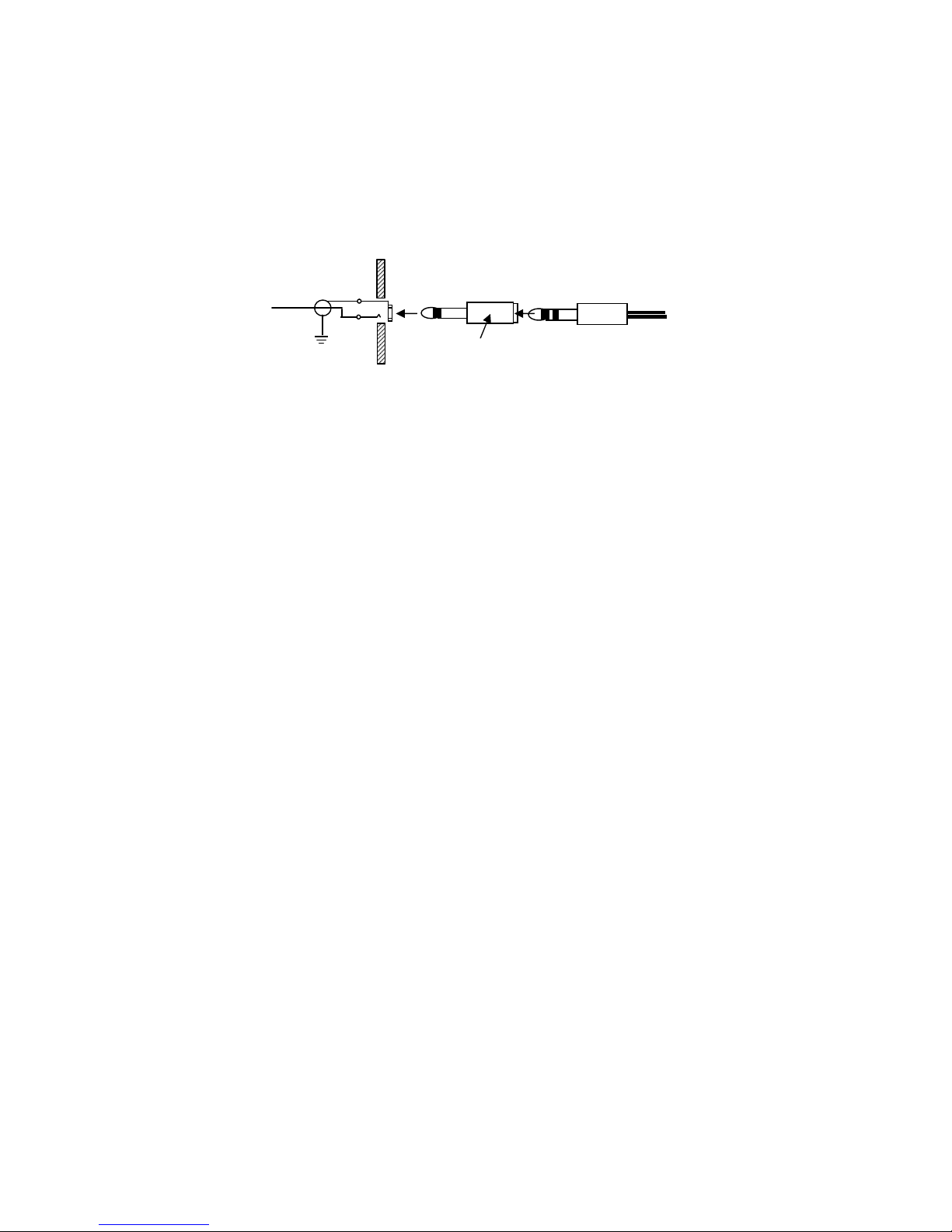
6.5mm (1/4")
3.2mm (1/8")
1.6mm (1/16")
BNC termination
BNC terminationBNC termination
BNC termination
Coaxial cable termination
Coaxial cable terminationCoaxial cable termination
Coaxial cable termination
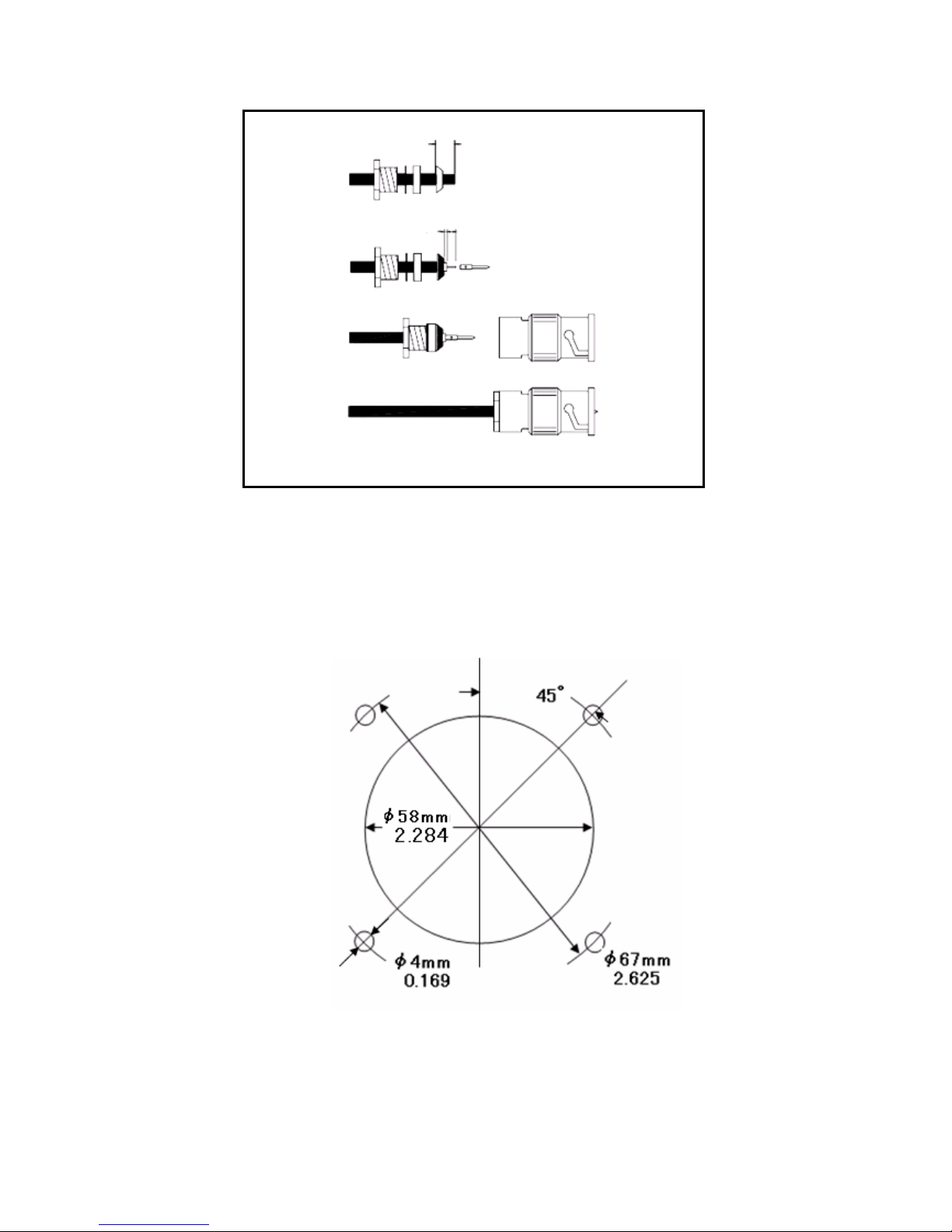
Radio ole cutout dimensions (drawing not to scale)
Radio ole cutout dimensions (drawing not to scale)Radio ole cutout dimensions (drawing not to scale)
Radio ole cutout dimensions (drawing not to scale)

Page 15
Limited Liability Warranty
Limited Liability Warranty Limited Liability Warranty
Limited Liability Warranty
Flig tline warrants t is product to be free from defects in materials and workmans ip for 1
year from t e date of purc ase or t e minimum period described by applicable consumer law.
If t e unit is installed by an organization w ic olds an avionics installation approval from
t e FAA, and t at organization as co-signed and dated t e warranty card, t e warranty
period s all be deemed to commence from t e date of installation.
T e customer s all be responsible for any transportation costs for return of t is product to
Flig tline.
T is warranty does not cover failures due to abuse, misuse, accident, unaut orized alteration,
or repairs carried out by parties ot er t an Flig tline or an approved Flig tline service center.
T is warranty does not cover failures w ere t e product as not been installed or operated, in
accordance wit t e provisions of t e User and Installation manual(s).
It s all be at Flig tline sole discretion to decide if a defect is a result of material or
workmans ip failure.
THE WARRANTIES AND REMEDIES CONTAINED HEREIN ARE EXCLUSIVE
AND IN LIEU OF ALL OTHER WARRANTIES EXPRESSED OR IMPLIED,
INCLUDING ANY LIABILITY ARISING UNDER WARRANTY OF
MERCHANTABILITY OR FITNESS FOR A PARTICULAR PURPOSE,
STATUARY OR OTHERWISE. THIS WARRANTY GIVES YOU SPECIFIC
LEGAL RIGHTS, WHICH MAY VARY FROM STATE TO STATE, AND
COUNTRY TO COUNTRY.
IN NO EVENT SHALL FLIGHTLINE BE LIABLE FOR ANY INCIDENTAL,
SPECIAL, INDIRECT OR CONSEQUENTIAL DAMAGES, WHETHER
RESULTING FROM THE USE, MISUSE OR INABILITY TO USE THIS
PRODUCT OR FROM DEFECTS IN THE PRODUCT.
Flig tline may at it discretion, refer product returns for repair or service, to a service facility
closest to you. Flig tline reserves t e rig t to repair or replace t e unit or software or offer a
full refund of t e purc ase price at it’s sole discretion.
SUCH REMEDY SHALL BE YOUR SOLE AND EXCLUSIVE REMEDY FOR ANY BREACH
OF WARRANTY.
Supplied by:
Supplied by:Supplied by:
Supplied by:
Flig tline 2008
All Rig ts Reserved
Printed in Japan February 2008
00M52AC851010
Table of contents
Other FLIGHT LINE Transceiver manuals


