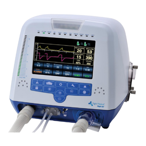
Flight Medical Innovations FLIGHT 50 User manual

FLIGHT MEDICAL INNOVATIONS LTD.
FLIGHT 50 Ventilator
Operator's Manual
LIT-0002 Rev. A00

Safety Instructions
General Warnings
Operator's Manual | ii
Legal Notice
Disclaimer
FLIGHT MEDICAL INNOVATIONS LTD. (FLIGHT MEDICAL) provides this
Operator’s Manual in its commitment to help reduce patient risk and injury.
However, this manual is not intended to in any way replace or substitute duty
of care to a patient, professional responsibility, or professional judgment, nor
is it intended to provide any warranty, promise, guarantee, assumption of risk
or duty, release, or indemnity. Physicians shall at all times maintain
responsibility for patient treatment and outcomes, and FLIGHT MEDICAL
further assumes no liability for patient treatment or outcome or for physician's
negligence, breach of duty of care, or malpractice.
The FLIGHT 50 Ventilator operator is solely responsible for selecting the
appropriate level and method of patient monitoring. Product modification or
misuse can be dangerous. FLIGHT MEDICAL disclaims all liability for the
consequences of product alterations or modifications, as well as for the
consequences which might result from the combination of this ventilator with
other products, whether supplied by FLIGHT MEDICAL or by other
manufacturers, unless such a combination has been specifically endorsed by
FLIGHT MEDICAL.
The design of FLIGHT 50 Ventilator, the Operator’s and Service Manuals, and
the labeling on the ventilator, take into consideration that the purchase and
use of the equipment is restricted to trained professionals, and that certain
inherent characteristics of the ventilator are known to the operator.
Instructions, warnings, and caution statements are therefore limited to the
specifics of the FLIGHT 50 Ventilator.
Federal law (US) restricts this device to sale by or on the
order of a physician.
This Operator’s Manual excludes references to various hazards which are
obvious to medical professionals and operators of this equipment, to the
consequences of product misuse, and to potential adverse effects in patients
with abnormal conditions.
When the FLIGHT 50 Ventilator is used in homecare and subacute
environments, only properly trained personnel should operate the ventilator.
FLIGHT 50 Ventilator is a restricted medical device designed for use by
respiratory therapists or other properly trained and qualified personnel under
the direction of a physician and in accordance with applicable state laws and
regulations.
Transport of patients with the FLIGHT 50 Ventilator requires that medical staff
have a good working knowledge of the ventilator’s use and problem resolution.
Proper emergency backup equipment must be immediately available during
transport.
FLIGHT 50 Ventilator operators must recognize their responsibility for
implementing safety monitoring mechanisms which supply appropriate

Safety Instructions
General Warnings
Operator's Manual | iii
information on equipment performance and patient condition. Patient safety
may be achieved through a wide variety of means, such as electronic
surveillance of equipment performance and patient condition. However,
equipment surveillance should not replace direct observation of clinical signs.
The liability of FLIGHT MEDICAL is subject to and limited to the exclusive
terms and conditions as set forth herein. Said liability is limited whether
arising out of, or related to, the manufacture and sale of goods, their
installation, demonstration, sales representation, use, performance, or
otherwise. Any liability based upon product warranty is limited regardless of
any fault attributable to FLIGHT MEDICAL and the nature of the action
(including breach of warranty, negligence, and strict liability).
The written warranties are in lieu of all other warranties, expressed or implied,
including, without limitation, warranties of merchantability, fitness for any
purpose, or non-infringement.
FLIGHT MEDICAL shall not be liable for any special incidental or consequential
damages incurred by the buyer to a third party. The buyer shall not be entitled
to make liability recoveries from FLIGHT MEDICAL due to such situations.
Warranty
FLIGHT 50 Ventilator warranty does not apply for/ in case of:
Defects caused by misuse, mishandling, tampering, or by
modifications not authorized by FLIGHT MEDICAL or its
representatives.
Rubber and plastic components and materials, which are guaranteed
to be free of defects at time of delivery.
Any product which proves during the warranty period to be defective in
workmanship or material, will be replaced, credited, or repaired. FLIGHT
MEDICAL retains the discretion to select the most suitable of these options.
FLIGHT MEDICAL is not responsible for deterioration, wear, or abuse. In all
cases, FLIGHT MEDICAL will not be liable beyond the original selling price.
Application of this warranty is subject to the following conditions:
FLIGHT MEDICAL or its authorized representatives must be promptly
notified upon detection of the defective material or equipment.
Defective material or equipment must be returned to FLIGHT
MEDICAL or its authorized representative.
Examination by FLIGHT MEDICAL or its authorized representatives
must confirm that the defect is covered by the terms of this
warranty.
The above is the sole warranty provided by FLIGHT MEDICAL. No other
warranty, expressed or implied, is intended. Representatives of FLIGHT
MEDICAL are not authorized to modify the terms of this warranty.
In no way does this or any of FLIGHT MEDICAL's policies, training materials,
guidelines, or instructions create an obligation for FLIGHT MEDICAL to perform
any services.

Safety Instructions
General Warnings
Operator's Manual | iv
Table of Contents
1SAFETY INSTRUCTIONS ..................................................................... 1-1
1.1 GENERAL WARNINGS ......................................................................... 1-1
1.2 CAUTIONS ...................................................................................... 1-3
1.3 CONTACT INFORMATION...................................................................... 1-4
2SPECIFICATIONS ............................................................................... 2-1
2.1 INTENDED USE ............................................................................. 2-1
3VENTILATOR DESCRIPTION ............................................................... 3-1
3.1 FRONT PANEL OVERVIEW .................................................................... 3-1
3.1.1 Turning the FLIGHT 50 Ventilator On/Off................................ 3-1
3.1.2 Changing the MODE Control ................................................. 3-1
3.1.3 Changing between Pressure Control and Volume Control.......... 3-2
3.1.4 Changing a Parameter (or Multiple Parameters) ...................... 3-2
3.1.5 Enabling/Disabling Auto Panel Lock ....................................... 3-3
3.2 FRONT PANEL CONTROLS AND INDICATORS ............................................... 3-3
On / Standby ............................................................................... 3-4
3.2.1 MODE Control..................................................................... 3-4
3.2.2 A/CMV Mode (Assist / Control Mandatory Ventilation) .............. 3-5
3.2.3 SIMV Mode (Synchronized Intermittent Mandatory Ventilation). 3-6
3.2.4 SPONT Mode (Spontaneous Ventilation) ................................. 3-6
3.2.5 ▲Up and ▼Down Control ................................................... 3-6
3.2.6 Frequency of Breaths (ƒ) ..................................................... 3-7
3.2.7 tI(Inspiratory Time) ............................................................ 3-8
3.2.8 Volume Control (tidal volume) .............................................. 3-8
3.2.9 Pressure Control (target pressure) ........................................ 3-9
3.2.10 Ptrig (sensitivity) ...............................................................3-10
3.2.11 PEEP/CPAP ........................................................................3-10
3.2.12 PSupport...........................................................................3-11
3.2.13 Manual Inflation.................................................................3-11
3.2.14 Humidifier On Button..........................................................3-12
3.2.15 (mandatory flow) ...........................................................3-13
3.2.16 I:E Ratio (inspiratory time to expiratory time) .......................3-13
3.2.17 Internal Battery Test Button and Indicator ............................3-14
3.2.18 Internal Battery Charge Level Meter .....................................3-14
3.2.19 Push to Unlock Button and Auto Lock Indicator ......................3-15
3.2.20 Silence / Reset ..................................................................3-15
3.2.21 Paw Meter (airway pressure meter) ......................................3-16
3.3 FRONT PANEL ALARMS.......................................................................3-16
3.3.1 High Paw and Low Paw Alarm Control and Display (Airway
Pressure) ....................................................................................3-16
3.3.2 ▲Paw (High Pressure) Alarm (user adjustable) .....................3-17

Safety Instructions
General Warnings
Operator's Manual | v
3.3.3 ▼Paw (Low Pressure) Alarm (user adjustable)......................3-17
3.3.4 High Iand Low IAlarm Control and Display (inspiratory
minute volume) ...........................................................................3-18
3.3.5 ▲I(High Insp. Minute Volume) Alarm (user adjustable) ......3-18
3.3.6 ▼I(Low Insp. Minute Volume) Alarm Back-up Ventilation (user
adjustable) .................................................................................3-19
3.3.7 High Baseline Pressure Alarm (automatic) .............................3-20
3.3.8 Occlusion Alarm, Circuit (automatic).....................................3-20
3.3.9 Occlusion Alarm, Device (automatic) ....................................3-20
3.3.10 Low Baseline Pressure Alarm (automatic)..............................3-21
3.3.11 Check Prox Line Alarm (automatic) ......................................3-21
3.3.12 Apnea Alarm (automatic) ....................................................3-22
3.3.13 PCV Not Reached Alarm (automatic).....................................3-22
3.3.14 Humidifier Alarm (automatic) ..............................................3-22
3.3.15 Battery Low Alarm .............................................................3-23
3.3.16 Battery Empty Alarm (automatic).........................................3-23
3.3.17 Fault, Battery System Alarm, Device Alert (automatic) ...........3-24
3.3.18 Power Switchover Alarm (automatic) ....................................3-25
3.3.19 Device Alert Alarm (automatic) ............................................3-25
3.3.20 Shut Down Alert Alarm (automatic) ......................................3-26
3.4 FRONT PANEL MESSAGE DISPLAY WINDOW ..............................................3-27
3.4.1 Message Monitoring............................................................3-27
3.4.2 Alarm and Caution Messages ...............................................3-28
3.4.3 Setting Limitation Messages ................................................3-28
3.5 LEFT SIDE CONNECTORS ....................................................................3-29
3.5.1 Airway Pressure Connector..................................................3-29
3.5.2 Gas Output Connector ........................................................3-29
3.5.3 Exhalation Valve Connector .................................................3-29
3.5.4 Temperature Probe Connector .............................................3-29
3.5.5 RS-232C Connector ............................................................3-29
3.5.6 Emergency Air Intake .........................................................3-29
3.6 RIGHT SIDE CONNECTORS ..................................................................3-30
3.6.1 Fresh Gas Intake and Filter Cover ........................................3-30
3.6.2 External Power Connector ...................................................3-30
3.6.3 Equipotential Connector ......................................................3-31
3.6.4 Power Cord Ferrite .............................................................3-31
3.7 OPTIONAL ACCESSORIES....................................................................3-31
3.7.1 Air/Oxygen Entrainment Mixer .............................................3-31
3.7.2 Oxygen Blending Bag Kit.....................................................3-32
3.7.3 Auto Lighter Cable .............................................................3-32
3.8 USER SET UP.................................................................................3-32
3.8.1 User Set Up Parameter .......................................................3-33

Safety Instructions
General Warnings
Operator's Manual | vi
4THEORY OF OPERATION..................................................................... 4-1
4.1 GENERAL SYSTEM OVERVIEW................................................................ 4-1
4.2 SETTING THE MAIN PARAMETERS ........................................................... 4-2
4.3 A/CMV MODE ................................................................................. 4-2
4.4 SIMV MODE (SYNCHRONIZED INTERMITTENT MANDATORY VENTILATION).......... 4-2
4.5 SPONT MODE (SPONTANEOUS VENTILATION) .......................................... 4-3
4.6 PSUPPORT (PRESSURE SUPPORT)........................................................... 4-4
4.7 PRESSURE CONTROL (PRESSURE CONTROL VENTILATION).............................. 4-4
4.8 VOLUME CONTROL (VOLUME CONTROL VENTILATION)................................... 4-4
4.9 BACK-UP VENTILATION ....................................................................... 4-5
4.9.1 Back-up Ventilation in A/CMV and SIMV Modes:...................... 4-5
4.9.2 Back-up Ventilation in SPONT Mode: ..................................... 4-5
4.9.3 Cancellation of Back-up Ventilation ....................................... 4-6
5VENTILATOR SETUP AND USE ............................................................ 5-1
5.1 INTRODUCTION ................................................................................ 5-1
5.2 ASSEMBLING THE VENTILATOR .............................................................. 5-1
5.3 VENTILATOR SET UP PROCEDURE ........................................................... 5-2
5.3.1 Exhalation Valve Calibration ................................................. 5-4
5.4 PATIENT SET UP PROCEDURE................................................................ 5-1
5.5 BUILT-IN HUMIDIFIER ........................................................................ 5-3
5.5.1 General Description ............................................................. 5-4
5.5.2 Preparation for Use ............................................................. 5-4
5.5.3 Set Up and Operation .......................................................... 5-5
5.6 OXYGEN ACCESSORIES ....................................................................... 5-6
5.6.1 Air / Oxygen Entrainment Mixer (Optional Accessory) .............. 5-6
5.6.2 Oxygen Blending Bag Kit (Optional Accessory)........................ 5-8
6CLEANING AND MAINTENANCE ........................................................ 6-12
6.1 CLEANING AND DISINFECTING..............................................................6-12
6.1.1 FLIGHT 50 Ventilator ..........................................................6-13
6.1.2 FLIGHT 50 Ventilator Accessories .........................................6-13
6.1.3 Humidifier Assembly (V51-00000-60 only) ............................6-13
6.1.4 Humidifier Temperature Probe .............................................6-15
6.1.5 Reusable Patient Circuits.....................................................6-16
6.2 MAINTENANCE ................................................................................6-21
6.2.1 Preventive Maintenance ......................................................6-21
6.2.2 Dual Internal Battery Maintenance .......................................6-21
6.2.3 15,000 Hour Maintenance ...................................................6-22
6.3 GENERAL WARNINGS ........................................................................6-22
7VENTILATOR QUICK CHECK PROCEDURE ........................................... 7-1
7.1 INTRODUCTION ................................................................................ 7-1

Safety Instructions
General Warnings
Operator's Manual | vii
7.1.1 Setting Up the Ventilator for the Test .................................... 7-1
7.2 QUICK CHECK PROCEDURE ............................................................ 7-2
7.2.1 Power Switchover Alarm Check ............................................. 7-2
7.2.2 Alarms and Indicators Check ................................................ 7-3
7.2.3 Paw Monitor / Pressure Meter Check...................................... 7-4
7.2.4 Volume/Frequency Monitor Check ......................................... 7-4
7.2.5 Internal Battery Check......................................................... 7-4
7.3 CHECK-OFF SHEET............................................................................ 7-5
7.4 ABBREVIATED CHECK PROCEDURE.................................................. 7-6
7.4.1 Inspection Check ................................................................ 7-6
7.4.2 Exhalation Valve Calibration ................................................. 7-6
7.4.3 Battery Function and Charge Level Verification ....................... 7-7
7.4.4 Operation Verification .......................................................... 7-7
8INDEX ................................................................................................ 8-1


Safety Instructions
General Warnings
Operator's Manual | 1-1
1 Safety Instructions
At all times, strictly follow this manual. The safe use of the FLIGHT 50
Ventilator requires full understanding of its operation, and adherence to the
manual's instructions. The equipment is only to be used for the purpose
specified in section 1.1. Observe all of the WARNINGS and CAUTIONS
posted in this manual, and on buttons found on the FLIGHT 50 Ventilator
and associated accessories.
1.1 General Warnings
External power connection: To maintain grounding
integrity when using AC power, only connect to hospital
grade receptacles. Always disconnect the external power
supply prior to servicing. There is a risk of explosion if
used in the presence of flammable anesthetics.
All settings and adjustments in the different ventilation
modes must be made in accordance with a physician's
prescribed therapy.
Do not use electrically conductive patient circuits.
Always use a clean, disinfected patient circuit.
Always use an outlet filter or equivalent at the Airway
Pressure Connector, to protect the internal transducers
from moisture and other contaminants.
The ventilator is ready for operation only when:
It is completely assembled.
The OVP has been successfully completed.
Failure to identify and correct alarm violations may result
in patient injury.

Safety Instructions
General Warnings
Operator's Manual | 1-2
Ensure that the oxygen source is not empty before and
during the use of the optional Air/Oxygen Entrainment
Mixer or Oxygen Blending Bag Kit.
As Li-Ion batteries are charged and discharged over time,
their ability to hold a charge is decreased with use. This
can shorten the amount of time the ventilator can
function while on battery power.
The batteries should be replaced when they no longer
meet the needs of the user. This depends on a number of
factors including settings and usage patterns.
Charge the batteries for a minimum of three hours before
powering the ventilator from the batteries. This ensures
that the batteries will be fully charged.
During storage, charge the batteries for a minimum of
three hours every 30 days. This improves the chances of
always having charged batteries.
Always ensure that the green Ext. Power LED is
illuminated after connecting the FLIGHT 50 Ventilator to
an external AC or DC power source. If the LED is not
illuminated, check all power connections and resolve any
problems.
Always plug the FLIGHT 50 Ventilator into an AC power
supply source when not in use. This will ensure the best
battery performance.
The flow resistance of the air inlet filter, located on the
right side of the ventilator, will likely increase with
repeated use. Ensure that the filter is changed regularly.
Only a FLIGHT MEDICAL approved patient circuit can be
used with the FLIGHT 50 Ventilator.

Safety Instructions
Cautions
Operator's Manual | 1-3
Only a FLIGHT MEDICAL approved exhalation valve can be
used with the FLIGHT 50 Ventilator.
Perform an exhalation valve calibration each time a clean
circuit/exhalation valve is installed.
The FLIGHT 50 Ventilator has been tested and found to comply with the
EMC limits according to the EN60601-1-1-2 standard class B. These limits
are designed to provide reasonable protection against harmful interference
in a typical medical installation. The equipment generates uses and can
radiate radio frequency energy and, if not installed and used in accordance
with these instructions, may cause harmful interference to other devices in
the vicinity. However, there is no guarantee that interference will not occur
in a particular installation. If it is found that this equipment causes harmful
interference with other devices, which can be determined by turning the
equipment off and on, the user is encouraged to try to correct the
interference by one or more of the following measures:
Reorient or relocate the receiving device.
Increase the distance between the equipment.
Connect the equipment into an outlet on a circuit different from
that to which the device (s) is connected.
Consult the manufacturer for help.
1.2 Cautions
Only use medical grade oxygen with the Air/Oxygen
Entrainment Mixer or Oxygen Blending Bag Kit.
Do not place liquid containers in the immediate vicinity or
on top of the FLIGHT 50 Ventilator. Liquids that get into
the ventilator can cause equipment malfunction and
damage.
After the FLIGHT 5050 Ventilator is serviced, it must
completely pass an Operational Verification Procedure
(OVP) before being returned to patient use.
An authorized FLIGHT MEDICAL factory-trained technician
must do all service or repairs performed on the FLIGHT
5050 Ventilator.

Safety Instructions
Contact Information
Operator's Manual | 1-4
Do not open the ventilator or perform service on an open
unit while connected to external power.
Use standard antistatic techniques while working inside
the ventilator or handling any electronic parts.
Clean all external accessories of the ventilator prior to
servicing.
Water in the oxygen supply can cause equipment
malfunction and damage.
Batteries contain Li-Ion. Do not discard them in an
incinerator or force them open. Batteries should not be
disposed of with normal waste.
Use the tools and equipment specified in this manual to
perform specific procedures.
1.3 Contact Information
Address further questions or problems to one of the FLIGHT MEDICAL
offices.
FLIGHT MEDICALINNOVATIONS Ltd.
Address: 13 Hamelacha St.,Lod 71520,ISRAEL
Tel: +972-8-923-5111
Fax: +972-8-923-6111
Email: info@flight-medical.com
Website: www.flight-medical.com
European Authorized Representative
Obeliss.a
Address: Boulevard GénéralWahis 53 1030 Brussels, BELGIUM
Tel: +32 2 7325954
Fax: +32 2 7326003
Email: mail@obelis.net

Specifications
INTENDED USE
Operator's Manual | 2-1
2 Specifications
2.1 INTENDED USE
FLIGHT 50 Ventilator is intended to provide continuous or intermittent
mechanical ventilation support for the care of individuals who require
mechanical ventilation. Specifically, the FLIGHT 50 is applicable for adult
and pediatric (i.e., infant, child and adolescent) patients, greater than or
equal to 10kg (22 lbs).
FLIGHT 50 Ventilator is a restricted medical device intended for use by
qualified, trained personnel under the direction of a physician; it is
suitable for use in hospital, sub-acute, emergency room, and home care
environments, as well as for transport and emergency response
applications. Front panel controls allow trained operators to select
between a number of operational modes, pressure support and volume
or pressure control. Flight 50 Ventilator has a comprehensive built-in
alarm system to alert the user to violations of set safety limits. When
new and fully charged, the internal battery system provides up to 10
hours of power. With its patented, self-contained gas supply source,
FLIGHT 50 Ventilator requires no external air compressor.

Specifications
SYMBOLS and SPECIFICATIONS
Operator's Manual | 2-2
2.2 SYMBOLS and SPECIFICATIONS
Main Power On
Alarm Setting
Main Power Standby
Audible Alarm Silence/Reset
Equipotentiality
High Alarm Set High Alarm
▼▼
Low Alarm Set Low Alarm
Refer to Operating Manual
Low Alarm Set Low Alarm
Applied Parts Type BF

Specifications
SYMBOLS and SPECIFICATIONS
Operator's Manual | 2-3
Controls/Alarms/Monitors
Range/Selection
MODE (Pressure or Volume Control)
A/CMV
SIMV
SPONT
Volume Control (Tidal Volume)
100 to 2,200 mL, ATPS, ± 10%
Pressure Control (Target Pressure)
PEEP +5 to 60 cmH2O / mbar
(Flow)
6 to 100 L/min
tI (Inspiratory Time)
0.1 to 3.0 sec
ƒ(Frequency)
1 to 99 b/min
Ptrig (Sensitivity)
–9.9 to 0 cmH2O / mbar, pressure triggering (Patient Effort
Indicator LED blinks once each time the airway pressure
reaches the Ptrig setting.)
PEEP/CPAP
0 to 30 cmH2O / mbar
P support (Pressure Support)
0 to 60 cmH2O / mbar above baseline pressure, limited to
PEEP + Psupport ≤ 60 cmH2O / mbar
I:E Ratio
1:99 to 3:1
Maximum Limited Airway Pressure
(Safety Valve)
100 cmH2O (98 mbar)
Manual Inflation
3 sec maximum
(While button is pushed, the ventilator closes the exhalation
valve and delivers an operator controlled breath to the
patient.)
Humidifier (Optional)
19ºC to 39ºC
Airway Pressure Meter
-10 to 100 cmH2O/-10 to 98 mbar
Alarm Silence/Reset Button & Indicator
Pressing the button silences an audible alarm violation for
60 seconds and resets a latched alarm indicator. LED lights
to indicate that Silence is active.
ALARMS Indicators
Indicators for violated alarms blink red. When the alarm is
no longer violated, the indicator latches (stays lit). Cancel a
latched indicator by pressing the Silence/Reset button.
Int. Battery Button and Indicator
Pressing the button displays the internal battery charge level
in the airway pressure meter (Paw) window. Use only when
operating on the internal battery system for accurate
reading. LED lights to indicate internal battery system
operation and alarms.
Controls/Alarms/Monitors
Range/Selection

Specifications
SYMBOLS and SPECIFICATIONS
Operator's Manual | 2-4
The time between the Battery Low Alarm violation and the Battery Empty
Alarm violation will vary depending on the ventilator load. At high volumes and
pressures, the Battery Empty Alarm will occur much sooner after the Battery
Low Alarm, than it will at lower volumes and pressures. In all cases, the stated
minimum times for each alarm will be met, even if the two alarms occur
almost simultaneously.
Device Alert (5 messages)
Ventilator malfunction: FAULT BAT SYS, OCCLUSION, 10V
SHUTDOWN, SYSTEM ERROR or MOTOR FAULT
Shut Down Alert
On to Standby/Off Shut Down Alert
FIO2(with optional accessories)
0.21 to 1.00
On / Standby Button
Press once to put in Setting condition. (On-Setting/LED off)
Press again to begin ventilating (On-Ventilating/LED on).
When the FLIGHT 50 Ventilator is ventilating, press two
times to put ventilator into Standby/Off condition (LED off).
Push To Unlock Buttons & Indicator
Pressing the button unlocks the front panel buttons, if they
were locked by automatic panel lock feature. Auto lock is
enabled/ disabled in User Set Up. LED lights to indicate panel
is locked.
Alarms
▲Paw (High Pressure)
4 to 99 cmH2O / 4 to 99 mbar, must be 1< Low Paw
▼Paw (Low Pressure)
3 to 98 cmH2O / 3 to 98 mbar, limited by ≥ PEEP + 3 and
High Paw -1
Low Baseline Pressure
Paw < PEEP - 3 cmH2O/mbar for 3 sec during exhalation
High Baseline Pressure
Paw > PEEP + 8 cmH2O/mbar at onset of a breath or 3 sec
after the start of exhalation
Occlusion
Paw > PEEP + 15 cmH2O/mbar at onset of a breath or 3 sec
after start of expiration
Apnea
30 sec ± 3 sec
PCV Not Reached
Paw P < 50% of PCV setting
▲IInsp. Min. Volume
1.1 to 50.0 L/min
▼IInsp. Min. Volume
0.1 to 49.0 L/min
Check Prox Line
Prox Paw does not match machine Paw during inspiration
Humidifier (5 messages)
Humidifier malfunction/disconnection
Power Switchover
External power to internal battery switchover alert
Battery Low
Minimum of 30 minutes battery time remains until shutdown
Battery Empty
Minimum of 15 minutes battery time remains until shutdown

Specifications
SYMBOLS and SPECIFICATIONS
Operator's Manual | 2-5
Message Display Window
Up to 16 characters, LED alpha
numeric display. Displayed
monitored parameters:
VT(Actual delivered tidal volume)
VI(Inspiratory minute volume)
ƒ(Total breath frequency)
Paw P (Peak airway pressure)
Paw M (Mean airway pressure )
Paw B (Baseline airway pressure)
H (Hours of operation)
S (Software version)
L (or Q) (Buzzer volume (Loud or Quiet) for audible alarm)
Other displayed parameters
(In USER SET UP):
Power Save (On / Off)
Airway Pressure Units (cmH2O / mbar)
Set Up (User / Default)
Auto Panel Lock (Enabled / Disabled)
Tech. Setup (Technical set up, refer to Service Manual)
Front Panel Indicators
Modes:
A/CMV
SIMV
SPONT
Green LED indicates that A/CMV mode is active.
Green LED indicates that SIMV mode is active.
Green LED indicates that SPONT mode is active.
Controls:
Volume Control
Pressure Control
Green LED indicates Volume Control ventilation.
Green LED indicates Pressure Control ventilation.
Alarms:
▲Paw (High Pressure)
▼Paw (Low Pressure) / Apnea
Device Alert
▲I(High Insp. Min. Volume)
▼I(Low Insp. Min. Volume)
(Back-Up Vent)
Red LED indicates high peak airway pressure, high baseline
pressure, or occlusion alarm violation.
Red LED indicates low peak airway pressure, low baseline
pressure, apnea, or PCV (50% of PCV setting not achieved)
alarm violation.
Red LED indicates ventilator malfunction alert.
Red LED indicates high inspiratory minute volume alarm
limit is violated.
Red LED indicates low inspiratory minute volume alarm limit
is violated.
Miscellaneous Indicators
Silence / Reset
Yellow LED indicates that the audible alarm is silenced for 60
seconds.
Auto Lock On
Green LED indicates that the panel is currently locked.
On / Standby
Green LED indicates that the FLIGHT 50 is ventilating.
Ptrig
Green LED blinks on to indicate patient breathing effort.

Specifications
SYMBOLS and SPECIFICATIONS
Operator's Manual | 2-6
(Flow)
Green LED indicates that Flow is displayed in the / I:E Ratio
numeric window display.
I:E
Green LED indicates that the I:E Ratio is displayed in the
/ I:E Ratio numeric window display. Blinking LED indicates
a breath with an inverse I:E Ratio.
Ext. Power / Charging Int.
Battery
Green LED indicates external power is on and the internal
battery is being charged. Red LED indicates power
switchover to internal battery.
Int. Battery (Push to Test)
Yellow LED indicates internal battery is in use. LED blinks
yellow to indicate Battery Low alarm condition or blinks red
to indicate Battery Empty alarm condition.
Humidifier On
Green LED indicates humidifier is active. LED blinks yellow to
indicate humidifier alarm condition.
Hardware
Requirements
Electrical
Applied parts type BF
External A.C. /D.C. (Battery Input)
100-240 VAC, max. 2 A
50 / 60 / 400 Hz
12-30 VDC, max. 12 A
Dual Internal Battery
Primary battery: lead acid, 12 VDC, 5 AH
Secondary back up battery: nickel metal hydride,12 VDC,
2.1 AH
When new and fully charged, the Dual internal battery supplies
power for up to 10 hours of operation at these settings: A/CMV
mode, ƒ=15, Volume Control=500 mL,
tI=1.0 sec, PEEP=Ø, max. airway pressure 30 cmH2O/mbar,
Power Save mode ON.
The dual internal battery charges whenever the FLIGHT 50
Ventilator is connected to an external power source.
Battery charge level is best maintained by keeping the
FLIGHT 50 Ventilator continuously connected to external
power.
The primary internal battery capacity diminishes with age.
As the battery ages the Battery Low alarm will occur
sooner. If this begins to infringe on the needed battery
time, prior to scheduled replacement, the primary internal
battery should be replaced.
RS-232C Interface /Remote Alarm
Output
8 pin SEMCONN connector. Operates at 19,200 baud. Allows
put for interfacing with central alarms systems
Pneumatics
Gas delivery system requires no external air compressor.

Specifications
SYMBOLS and SPECIFICATIONS
Operator's Manual | 2-7
Miscellaneous
Description
Operating Temperature
–18ºC to 50ºC
For proper operation at low range temperatures (-18°C), the
FLIGHT 50 Ventilator must be started in a normal room
temperature environment and allowed to run for 30
minutes prior to transfer to colder environment.
At temperatures over 40ºC the charging circuit is disabled
and the internal battery does not charge.
Operating Humidity
15 to 95% non-condensing
Operating Altitude
Sea level to 15,000 ft (0 to 4,572 m)
There is no altitude limitation when FLIGHT 50 Ventilator is
operated in a pressurized environment.
Operating Pressure
600 to 1,100 mbar
Regulatory and Agency
Standards/Requirements
Complies with the following international standards and
requirements:
IEC 60601-1:1988 (+A1:1991 +A2:1995; EN 60601-1:1990
+A1:1993 +A2:1995 +A3:1996) Medical Electrical
Equipment –Part 1: General Requirements for Safety
CEI/IEC 60529:2001 Degrees of Protection Provided by
Enclosures (IP Code)
IEC 60601-1-2:2001 (+A1:2006) Medical Electrical Equipment,
Collateral Standard: Electromagnetic Compatibility –
Requirements and Tests
IEC 68-2-6 Test Fc Environmental Tests: Vibration
(sinusoidal)
IEC 68-2-29 Test Eb Environmental Tests: Bump
IEC 68-2-32 Test Ed Environmental Tests: Free Fall
IEC 68-2-36 Test Fdb Environmental Tests: Random Vibration
Storage Temperature
–40ºC to 65ºC
Storage Humidity
0 to 95% non-condensing
Height (includes handle)
10 inches (26 cm)
Width
11 inches (27 cm)
Depth
8 inches (20 cm)
Weight
16.7 lbs. (7.6 kg) without humidifier
18.0 lbs. (8.2 kg) with humidifier

Specifications
SYMBOLS and SPECIFICATIONS
Operator's Manual | 2-8
Patient Range
Adult - Pediatric (i.e. infant, child & adolescent) with body
weight >10 kg
Factory Default Parameters
Patient Settings
MODE
A/CMV
Volume Control
500 mL
tI
1.0 sec
ƒ
15 b/min
Ptrig
-1.0 cmH2O
Paw Alarms
5 cmH2O Paw
40 cmH2O Paw
IAlarms
3 L/min I
20 L/min I
PEEP/CPAP
0 cmH2O
Psupport
0 cmH2O
Humidifier
Off
Buzzer Volume
Loud
User Set Up
Power Save
Pressure Units
Auto Panel Lock
Set Up
On
cmH2O
Disabled
User
Patient Circuit
Reusable 22 mm I.D. adult/pediatric circuit with 3/16 inch
(4.8 mm) I.D. proximal pressure sensing line, 1/8 inch
(3.2 mm) I.D. exhalation valve control drive line, and
exhalation valve.
Exhalation Valve
FLIGHT MEDICAL’S FLIGHT 50 exhalation valve (P/N V54-00000-
67) is manufactured and designed specifically for the FLIGHT 50
Ventilator. FLIGHT MEDICAL does not approve of the use of
any type or brand of exhalation valve that has not been tested
and approved by FLIGHT MEDICAL for use with the FLIGHT 50.
FLIGHT 50 HUMIDIFIER
(operates on A.C. power only)
Set Target Temperature Range
19ºC to 39ºC
Operating Water Volume
300 mL
Usable Volume of Water Bottle
265 mL
Compliance at Minimum Water Level
0.5 mL/cmH2O / mbar @ 23ºC
Table of contents
Other Flight Medical Innovations Medical Equipment manuals
Flight Medical Innovations
Flight Medical Innovations Flight 60 iO2 User manual

Flight Medical Innovations
Flight Medical Innovations Flight 60 iO2 User manual
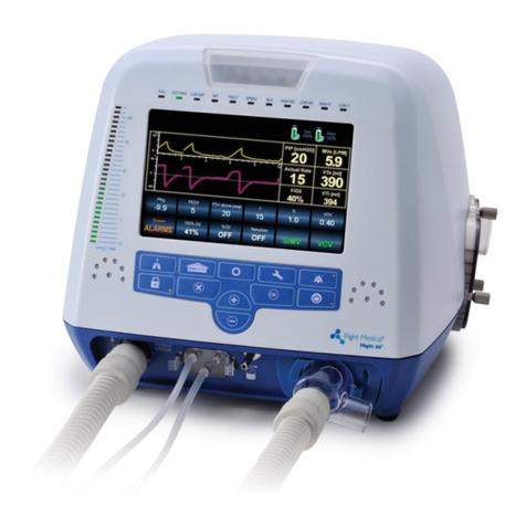
Flight Medical Innovations
Flight Medical Innovations FLIGHT 60T Series User manual
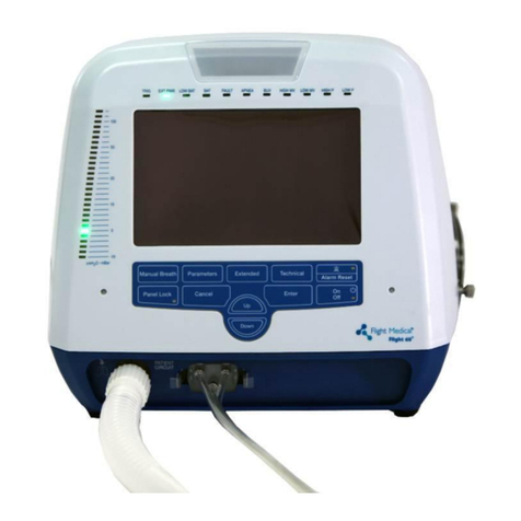
Flight Medical Innovations
Flight Medical Innovations Flight 60 Ventilator User manual
Popular Medical Equipment manuals by other brands
Acare Technology
Acare Technology lifebox quick guide
Owlet
Owlet Band manual
Invacare
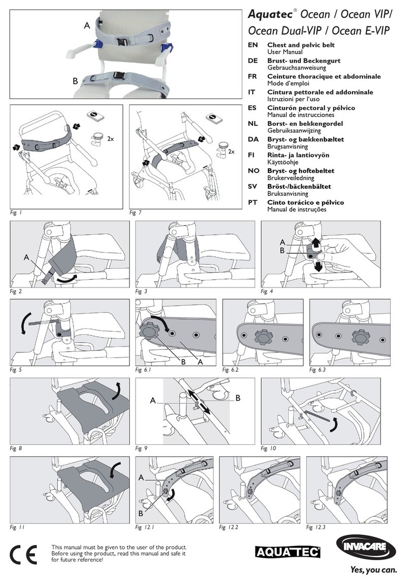
Invacare Aquatec Ocean VIP user manual
AD Maiora
AD Maiora ERGOMED 99-2M-E instruction manual
Utah Medical Products
Utah Medical Products Filshie Sterishot II Inservice Reference Guide

Synthes
Synthes SynFrame Light-transmitting Rod 387.362 Instructions for use
