FlightSafety LEARJET 45 Installation guide


Courses for the Learjet 45 and other Learjet aircraft are taught at the
following FlightSafety Learning Centers:
FlightSafety International
Tucson Learning Center
1071 East Aero Park Blvd.
Tucson, AZ 85706
(800) 203-5627 • Fax (520) 918-7111
FlightSafety International
Atlanta Learning Center
1010 Toffie Terrace
Atlanta, GA 30354
(800) 889-7916 • Fax (678) 365-2699
Copyright © 1997 by FlightSafety International, Inc. All rights reserved.
Printed in the United States of America.

iii
FOR TRAINING PURPOSES ONLY
FOR TRAINING PURPOSES ONLY
NOTICE
The material contained in this training manual is based on in-
formation obtained from the aircraft manufacturer’s Pilot Manuals
and Maintenance Manuals. It is to be used for familiarization and
training purposes only.
At the time of printing it contained then-current information. In
the event of conflict between data provided herein and that in
publications issued by the manufacturer or the FAA, that of the
manufacturer or the FAA shall take precedence.
We at FlightSafety want you to have the best training possible.
We welcome any suggestions you might have for improving this
manual or any other aspect of our training program.

v
CONTENTS
Chapter 1 AIRCRAFT GENERAL
Chapter 2 ELECTRICAL POWER SYSTEMS
Chapter 3 LIGHTING
Chapter 4 MASTER WARNING SYSTEM
Chapter 5 FUEL SYSTEM
Chapter 6 AUXILIARY POWER UNIT
Chapter 7 POWERPLANT
Chapter 8 FIRE PROTECTION
Chapter 9 PNEUMATICS
Chapter 10 ICE AND RAIN PROTECTION
Chapter 11 AIR CONDITIONING
Chapter 12 PRESSURIZATION
Chapter 13 HYDRAULIC POWER SYSTEMS
Chapter 14 LANDING GEAR AND BRAKES
Chapter 15 FLIGHT CONTROLS
Chapter 16 AVIONICS
Chapter 17 MISCELLANEOUS SYSTEMS
WALKAROUND
APPENDIX

1-i
CHAPTER 1
AIRCRAFT GENERAL
CONTENTS
Page
INTRODUCTION ................................................................................................................... 1-1
GENERAL............................................................................................................................... 1-2
STRUCTURES ........................................................................................................................ 1-2
General ............................................................................................................................. 1-2
Fuselage ........................................................................................................................... 1-2
Wing............................................................................................................................... 1-15
Empennage..................................................................................................................... 1-17
Static Discharge Wicks .................................................................................................. 1-18
Airplane Antennas ......................................................................................................... 1-19
REVIEW QUESTIONS ........................................................................................................ 1-20
FOR TRAINING PURPOSES ONLY
LEARJET 45 PILOT TRAINING MANUAL
FlightSafety
international

1-iii
ILLUSTRATIONS
Figure Title Page
1-1 Learjet 45.................................................................................................................. 1-2
1-2 General Dimensions................................................................................................. 1-3
1-3 Turning Radius......................................................................................................... 1-4
1-4 Danger Areas............................................................................................................ 1-5
1-5 Fuselage Sections..................................................................................................... 1-6
1-6 Nose Section Avionic Access Panel (Left Side) ...................................................... 1-6
1-7 Nose Section Avionic Access Panel (Right Side) .................................................... 1-6
1-8 Cockpit Layout (Typical) ......................................................................................... 1-8
1-9 Instrument Panel....................................................................................................... 1-9
1-10 Airplane Doors....................................................................................................... 1-10
1-11 Passenger/Crew Entry Door (Closed/Open) .......................................................... 1-11
1-12 Airplane Door Messages and Warnings................................................................. 1-12
1-13 Door Latch Inspection Ports and Inside Locking Handle...................................... 1-13
1-14 Emergency Exit Hatch ........................................................................................... 1-13
1-15 Windshield and Window Locations ....................................................................... 1-14
1-16 Tailcone Access Doors........................................................................................... 1-15
1-17 Wing Configuration ............................................................................................... 1-16
1-18 Learjet 45 Wing ..................................................................................................... 1-17
1-19 Learjet 45 Empennage ........................................................................................... 1-17
1-20 Airplane Static Discharge Wicks ........................................................................... 1-18
1-21 Airplane Antennas ................................................................................................. 1-19
FOR TRAINING PURPOSES ONLY
LEARJET 45 PILOT TRAINING MANUAL
FlightSafety
international
INTRODUCTION
This training manual provides a description of the major airframe and engine systems
installed in the Learjet 45 Model. This chapter covers the structural makeup of the air-
plane and gives a general description of the systems.
The material presented has been prepared for the basic design data, and all subsequent
changes in airplane appearance or system operation will be covered during academic train-
ing and in subsequent revisions to this manual. No material is meant to supersede or sup-
plement any of the manufacturer’s system or operating manuals.
LEARJET 45 PILOT TRAINING MANUAL
FlightSafety
international
CHAPTER 1
AIRCRAFT GENERAL
1-1
FOR TRAINING PURPOSES ONLY
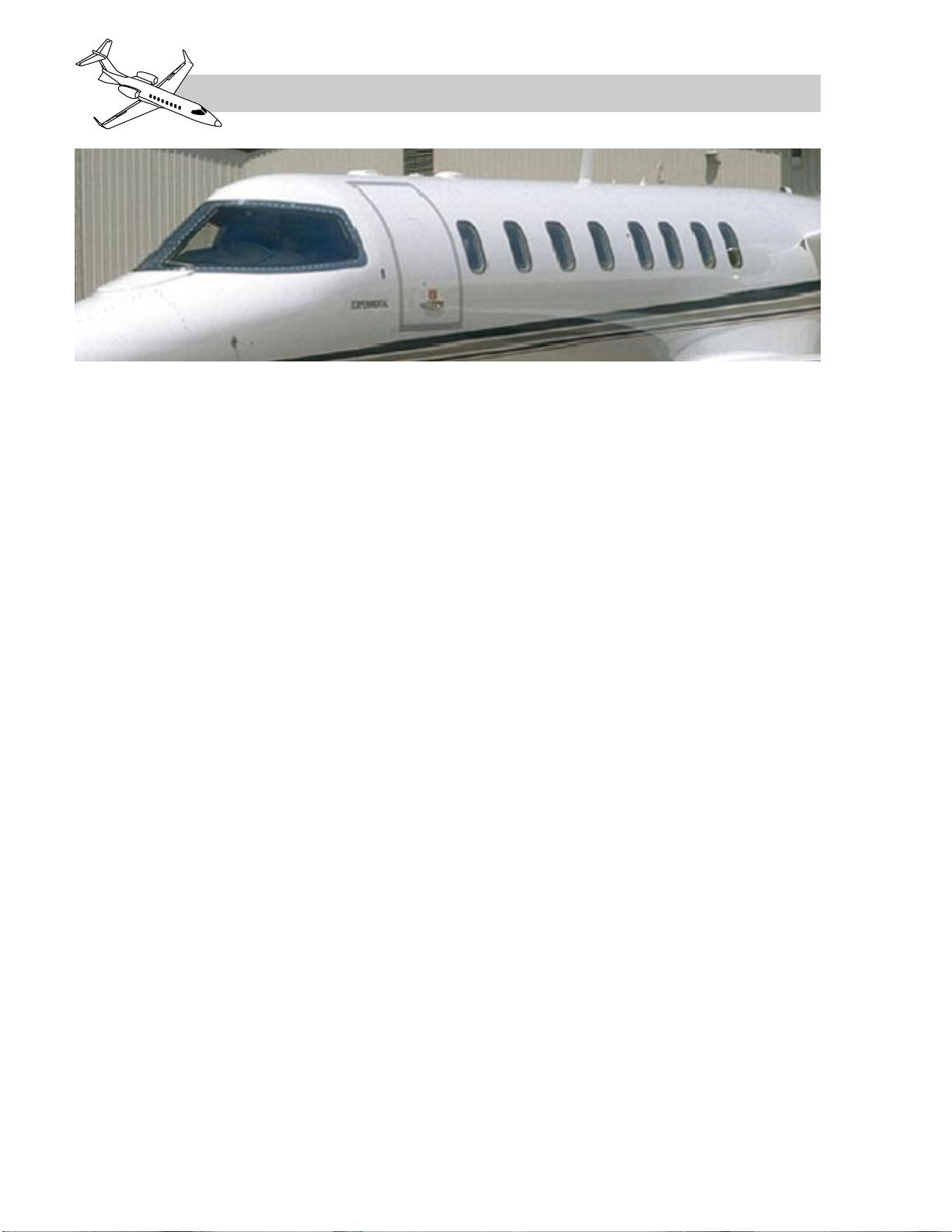
GENERAL
The Learjet 45 is certified under FAR Part 25
and Part 36 as a transport category airplane. The
aircraft is also certified under EC JAR 25
(European Community–Joint Airworthiness
Requirements). It is designed for all-weather
operation, and cleared for operation up to
51,000 feet and to 0.81 Mach (Figure 1-1).
STRUCTURE
GENERAL
The Learjet 45 aircraft structural design meets
or exceeds FAR Part 25 requirements with re-
spect to fatigue and damage tolerance evalua-
tion. The structure consists of the fuselage,
the wing, the empennage and flight controls.
The discussion on the fuselage includes all
doors and windows. Figure 1-2 illustrates the
general dimensions of the airplane.
Figure 1-3 displays the Learjet 45 turning ra-
dius, based upon a nosewheel orientation of
60 degrees from center at slow speed.
Figure 1-4 is the manufacturer’s display of
danger areas around the Learjet 45. Areas por-
trayed represent the weather radar transmission
cone as well as sections in front of the engine
intakes and aft of the engine exhaust cone.
FUSELAGE
General
The fuselage is made of conventional metal,
semimonocoque construction, of near circu-
lar cross–section. The fuselage is constructed
in three major assemblies and then mated into
four basic sections (Figure 1-5). They are:
1. The nose section, which extends from
the radome aft to the forward pressure
bulkhead.
2. The pressurized section, which includes
the cockpit and passenger areas, extends
aft to the rear pressure bulkhead.
3. The fuselage fuel section, which starts
just aft of the rear pressure bulkhead
and extends to the tailcone.
4. The tailcone section, consisting of the
portion of the airplane aft of the fuel sec-
tion.
The fuselage also incorporates attachments
for the wings, tail group, engine support py-
lons, and the nose landing gear.
LEARJET 45 PILOT TRAINING MANUAL
1-2
FOR TRAINING PURPOSES ONLY
FlightSafety
international
Figure 1-1. Learjet 45

LEARJET 45 PILOT TRAINING MANUAL
FlightSafety
international
1-3
FOR TRAINING PURPOSES ONLY
Figure 1-2. General Dimensions
17.2'
9.3'
45.8'
47.8'
3.7'
3.7'
2.3'
5.4'
9.9'
58.4'
14.3'

LEARJET 45 PILOT TRAINING MANUAL
1-4
FOR TRAINING PURPOSES ONLY
FlightSafety
international
Figure 1-3. Turning Radius
N
O
S
E
W
H
E
E
L
W
I
N
G
T
I
P
NOTE: TURNING RADIUS EXPRESSED ABOVE IS BASED UPON 60 NOSEWHEEL DEFLECTION.
39' ft. 4 in.
(1,199 cm)
30 ft. 1 in.
(917 cm)
FS 141.85 FS 454.87
FBL 180.72

LEARJET 45 PILOT TRAINING MANUAL
FlightSafety
international
1-5
FOR TRAINING PURPOSES ONLY
Figure 1-4. Danger Areas
ENGINE INTAKE
12 FEET (4 M)
WEATHER RADAR
9 FEET (2.7 M)
ENGINE EXHAUST
750°F (399°C)
100°F
(38°C) 40 FEET (12 M)
NOTE: EXHAUST DANGER AREA
SHOWN FOR IDLE RPM. VALUES
APPROXIMATELY DOUBLE FOR
TAKEOFF RPM.
NOTE:
NOTE:
THE ANTENNA SCAN AREA
MUST BE FREE OF METALLIC
OBJECTS FOR A DISTANCE
OF AT LEAST 100 FEET.
REFUELING OPERATION
MUST NOT BE PERFORMED
WITHIN 100 FEET OF THE
ANTENNA SCAN AREA.

In addition to the cockpit and passenger com-
partments, the fuselage includes a nose wheel-
well, an unpressurized, heated, tailcone
baggage compartment, and an unpressurized
tailcone equipment bay.
Nose Section
At the nose of the fuselage is the radome.
Constructed of fiberglass honeycomb, the
radome houses the weather radar. Aft of the
radome the nose section is constructed of alu-
minum alloy materials and provides housing
for the avionics equipment, the subfloor equip-
ment bay, the forward pressure bulkhead and
the nose wheelwell.
Two removable access panels, one on each
side of the nose section, provide access to the
avionic equipment (Figures 1-6 and 1-7). The
panels are secured with camlock fasteners.
The nose section avionics bay is cooled in
flight by the air outflow from the pressurized
section which is exhausted into the nose wheel-
well.
LEARJET 45 PILOT TRAINING MANUAL
1-6
FOR TRAINING PURPOSES ONLY
FlightSafety
international
NOSE
SECTION PRESSURIZED SECTION FUEL
SECTION TAILCONE SECTION
REAR OF FUEL
COMPARTMENT
AFT PRESSURE
BULKHEAD
FORWARD
PRESSURE
BULKHEAD
FORWARD
EDGE OF DOOR
AFT EDGE
OF DOOR
Figure 1-5. Fuselage Sections
Figure 1-6. Nose Section Avionic Bay
(Left Side)
Figure 1-7. Nose Section Avionic Bay
(Right Side)
Pressurized Section
The pressurized area is between the forward
pressure bulkhead and the aft pressure bulk-
head. This primarily circular section includes
the cockpit and the passenger area and in-
cludes a lavatory.
The cockpit and cabin are separated by di-
viders. The cockpit extends from the forward
pressure bulkhead approximately 60 inches
to the cabin divider. The cockpit (typical) is
illustrated in Figure 1-8.
The passenger cabin extends from the cabin
divider approximately 19.75 feet (237 inches)
to the aft pressure bulkhead. The passenger
cabin offers a flat floor, a maximum height of
4.9 feet (59 inches) and a maximum width of
5.1 feet (61 inches). Sixteen cabin windows
with sun shades are provided. The standard in-
terior includes a coat closet and a full galley
in the forward cabin. An enclosed aft lavatory
features an externally-serviced flushing toi-
let. The standard cabin provides seating for
eight passengers and an option is available to
use the lavatory for a ninth passenger seat.
The standard lavatory provides 15 cu.ft. of
baggage volume in addition to the 50 cu.ft. of
tailcone baggage.
The instrument panel (typical) is displayed
in Figure 1-9.
The two piece passenger/crew door is located
on the left side of the fuselage, just aft of the
cockpit. An emergency exit door/hatch is located
on the right side, over the wing leading edge.
There are sixteen total cabin windows, eight
on each side. Within the passenger compart-
ment there are fourteen windows. The sixth
cabin window aft on the right side is located
within the emergency exit. There are two win-
dows located in the lavatory section, one on
each side.
LEARJET 45 PILOT TRAINING MANUAL
FlightSafety
international
1-7
FOR TRAINING PURPOSES ONLY

LEARJET 45 PILOT TRAINING MANUAL
1-8
FOR TRAINING PURPOSES ONLY
FlightSafety
international
Figure 1-8. Cockpit Layout (Typical)
1. PEDESTAL AND THROTTLE QUADRANT
2. AIR OUTLETS (ANKLE)
3. PILOT'S CIRCUIT BREAKER PANEL
4. COPILOT'S CIRCUIT BREAKER PANEL
5. PUBLICATION STORAGE AREAS
6. AIR OUTLETS (WEMAC)
7. MAP LIGHTS
8. SUNVISOR
9. DOME LIGHT
10. PILOT'S CONTROL COLUMN AND WHEEL
11. COPILOT'S CONTROL COLUMN AND WHEEL
12. INSTRUMENT PANEL
13. MAGNETIC COMPASS
14. CREW WARNING PANEL
2 2
1
34
55
6 6
7
898
9
7
10 11
12 13 14

LEARJET 45 PILOT TRAINING MANUAL
FlightSafety
international
1-9
FOR TRAINING PURPOSES ONLY
THROTTLE
QUADRANT
ENGINE/FUEL PANEL
FLIGHT
MGMT
SYSTEM
APU
TRIM
HF
SELCAL
WX RADAR
SYS TEST/CDH
PILOT'S
PRIMARY
FLIGHT
DISPLAY
EICAS
AUDIO
CWP
RMU-1 RMU-2
MULTI-
FUNCTION
DISPLAY
CO-PILOT'S
PRIMARY
FLIGHT
DISPLAY
AUDIO
DISPLAY
CONTROLLER
FLIGHT GUIDANCE
CONTROLLER
1 1
22
3
3
4
19
56
7 7
8 89 910 11 12 13 14 15 16 17
1 - L/R DISPLAY UNIT REV PANEL
2 - L/R AOA INDICATOR (OPTIONAL)
3 - L/R DIGITAL CHRONOMETER
4 - STANDBY AIRSPEED INDICATOR
5 - STANDBY ATTITUDE INDICATOR
6 - STANDBY ALTIMETER
7 - L/R RUDDER PEDAL ADJUSTMENT
8 - L/R CREW LIGHTS PANEL
9 - L/R AHRS PANEL
10 - ELECTRICAL CONTROL PANEL
11 - REVERSION CONTROL PANEL
12 - ANTI-ICE PANEL
13 - AIRPLANE LIGHT CONTROL
14 - GEAR/HYDRAULIC PANEL
15 - CABIN PRESS/OXYGEN PANEL
16 - ENVIRONMENTAL CONTROL
17 - CVR CONTROL PANEL
18 - SLIP/SKID INDICATORS
19 - STANDBY COMPASS
DU-1 DU-2 DU-3 DU-4
18
18
DISPLAY
CONTROLLER
Figure 1-9. Instrument Panel (Typical)
Doors
Passenger/Crew Door
The passenger/crew door is the primary means
of ingress and egress for the passengers and
the crew (Figure 1-10). The 30-inch-wide door
has a clamshell design, each half hinged to the
fuselage. The upper half also serves as an
emergency exit. The bottom half has two in-
tegral entrance steps and a lower flip down step
(Figure 1-11). The lower step must be folded
in when the lower door is closed.
The upper portion of the door has both outside
and inside locking handles which are fastened
to a common shaft through the door. Rotating
either of these handles to closed drives six
locking pins into the fuselage frame (three
pins forward and three aft) and two pins
through interlocking arms on the lower door
that secure the door halves together.
The upper entry door has a small vent door lo-
cated in the center of it. When the inside or out-
side upper door handle is rotated to the open
position the vent door cycles open and then
closed. Through the arrangement in the upper
door opening mechanism, the vent door opens
before the locking pins are retracted and then
closes again when the locking pins are fully
retracted.
The lower door has a single locking handle on
the inside of the door. Rotating the lower door
handle to the closed (forward) position drives
four pins into the fuselage frame (two for-
ward and two aft).
LEARJET 45 PILOT TRAINING MANUAL
1-10
FOR TRAINING PURPOSES ONLY
FlightSafety
international
Figure 1-10. Airplane Doors
EMERGENCY DOOR
(RIGHT SIDE)
HANDLE
1G
MAIN DOOR
VENT DOOR
BAGGAGE DOOR
(LEFT SIDE)
TAILCONE ACCESS DOOR
(RIGHT SIDE)
1G
LOCKING PIN / MICROSWITCH COMBINATION
OVER-CENTER MECHANISM MICROSWITCH

There are a total of 12 locking pins on the two
door sections. When the door handles are in
the closed position, each pin makes contact
with a microswitch. If any of the switches are
not tripped when the door handles are closed
warning and advisory messages remain illu-
minated to alert the crew (Figure 1-12).
A red “ENTRY DOOR” warning light on the
CWP (crew warning panel) and a red “ENTRY
DOOR” message on the CAS (engine instru-
ment/crew alerting system) illuminates when-
ever any of the 12 pins on the entry door are
not in the closed position.
A white “ENTRY DOOR PIN” advisory mes-
sage will also appear on the CAS when the air-
plane is on the ground with the door open and
the entry door pins are not all fully open. It will
be accompanied by the ENTRY DOOR warn-
ing indications.
Also, the “ENTRY DOOR” CWP annunciator,
and the “ENTRY DOOR” and “ENTRY
DOOR PIN” CAS messages all illuminate if
the DOOR circuit breaker on the pilot circuit
breaker panel is out.
Amber caution messages are also displayed on
the CAS for additional access doors that are
not secure (i.e. tailcone access door, the bag-
gage door and the emergency exit door). These
same CAS messages are illuminated when-
ever the corresponding doors are opened in-
tentionally.
Visual backups, to insure the passenger/crew
door is secured, consist of sight holes located
on the inside of the doors. These sight holes
allow for a visual inspection to confirm that
the pins have engaged properly. The sight
holes (Figure 1-13) are located on both the
upper and lower doors.
LEARJET 45 PILOT TRAINING MANUAL
FlightSafety
international
1-11
FOR TRAINING PURPOSES ONLY
VENT DOOR
KEYLOCK
OUTSIDE
HANDLE
Figure 1-11. Passenger/Crew Entry Door (Closed/Open)
PULL-UP
CABLE
LOWER
HANDLE

Upper passenger/crew door opening and clos-
ing is assisted by a pair of gas struts. The gas
struts, when fully extended, hold the door open.
A keylock provides positive outside security
for the main entry upper door locking mech-
anism, but must not be employed when the
airplane is occupied since the upper door also
serves as an emergency exit. To alert the crew
to this situation, the red ENTRY DOOR light
on the CWP illuminates whenever the key-
lock is engaged and electrical power is ap-
plied to the airplane. The red “ENTRY DOOR”
and the white “ENTRY DOOR PIN” messages
are also displayed on the CAS in this situation.
LEARJET 45 PILOT TRAINING MANUAL
1-12
FOR TRAINING PURPOSES ONLY
FlightSafety
international
N1
ITT
SAT C
CAS
FUEL
FLT
ECS
HYD
ELEC
SUMRY
LF
1000 R1750 FLAPS 20
6.5
PITCH TRIMLBSFUEL 4450
-15
50.0
76
60
984
50.0
80
60
1002
N2
OIL PSI
OIL C
FF PPH
550 550
75.0
75.0
1700
ELECT
VOLTS
EMER-V
AMPS
TEMP C
28.5 28.0
28.0
200 300
30 50
HYD/ECS
MAIN
B-ACUM
OXY C
OXY PSI
3000
2000
+10
1800
FLT
SPLR
PIT
AIL
RUD
0
0
R 3
L 2
Honeywell
Honeywell
ENTRY DOOR
EMERGENCY EXIT
EXTERNAL DOORS
ENTRY DOOR PIN
END
R REV
UNSAFE
R OIL
PRESS
LOW
RENG
PYLON
OVHT
RFUEL
PRESS
LOW
ENTRY
DOOR
GENFAIL
RBLEED
AIR
LEAK
RBATT
OVHT
STAB
OVHT
EMER
BATT
WING/
STAB
LEAK
LBATT
OVHT
WING
OVHT
GEAR
LBLEED
AIR
LEAK
NORMAL
BRAKES
FAIL
L ENG
PYLON
OVHT
LFUEL
PRESS
LOW
L REV
UNSAFE
L OIL
PRESS
LOW
CAS Message Logic Summary
W
C
C
A
W = Warning C = Caution A = Advisory
ENTRY DOOR
EMERGENCY EXIT
EXTERNAL DOORS
ENTRY DOOR PIN
Any main entry door pin not closed, or key locked (gnd only)
Emergency escape hatch exit not fully latched
Tailcone or baggage door not fully latched
Any pin not in agreement with the door open,
or key locked (gnd only)
TYPE
MSG
ENTRY
DOOR
ENTRY DOOR
EMERGENCY EXIT
EXTERNAL DOORS
ENTRY DOOR PIN
END
Figure 1-12. Airplane Door Messages and Warnings

The lower passenger/crew door has a cable
that is used to pull the door closed from the
inside. A secondary latch, located on the for-
ward door frame engages a catch on the upper
forward corner of the lower door, when the
door is closed. The tab on this spring loaded
latch has to be raised to open the lower door.
This door is also equipped with gas dampers
for opening and closing. When fully open, the
door is supported by stops within the dampers.
A rubber seal fastened around the main door
frame allows pressurized cabin air to enter,
forming a positive seal around the door.
Emergency Exit Hatch
The removable emergency exit door (hatch) is
located on the right side of the fuselage (Figure
1-14). The 20 by 36 inch emergency hatch
contains both an internal and an external latch
release mechanism. From inside the airplane,
the door may be secured by a “REMOVE BE-
FORE FLIGHT” flagged security pin that re-
stricts movement of the locking pins when
inserted.
From inside the aircraft, the emergency exit
door is opened by pulling the internal latch
handle, labeled “EXIT–PULL,” downwards.
This extracts the two locking pins, located at
the top of the hatch. The exit door can then be
pulled inward. The bottom edge of the emer-
gency exit door sits behind a lip that serves as
a non-retaining hinge during removal and in-
stallation of the emergency exit.
The emergency exit door may be opened from
outside the airplane, once the internal security
pin has been removed, by depressing the PUSH
panel at the top of the door. This action per-
forms the same unlatching of the locking pins
as does pulling the latch assembly handle from
inside the airplane. The door can then be
pushed inward and set aside. The hatch weighs
approximately 35 pounds.
Whenever the emergency exit locking mech-
anism has been disengaged, an amber caution
message, “EMERGENCY EXIT” is displayed
on the CAS (Figure 1-12).
LEARJET 45 PILOT TRAINING MANUAL
FlightSafety
international
1-13
FOR TRAINING PURPOSES ONLY
Figure 1-14. Emergency Exit Hatch
Figure 1-13. Door Latch Inspection Ports
and Inside Locking Handle
Windows
Windshield
The windshield consists of the pilot’s and co-
pilot’s windshield halves (Figure 1-15). The
windshields are of a sandwich construction uti-
lizing two plies. The exterior surface is scratch
resistant glass and is coated with a substance
that readily sheds rain droplets. The inner ply
is made of polycarbonate material and provides
the structural protection for the crew. The
windshields have an electrically powered in-
tegral heating element between the layers for
complete deicing and internal defogging.
Cabin Windows
There are sixteen cabin windows; seven on
each side of the passenger compartment and
one on each side in the lavatory. They are
made of two separate panes of acrylic plastic
with an air space between. One window is lo-
cated in the emergency exit door/hatch. Each
window has an accordion type shade installed.
Fuel Section
The fuel section is located aft of the rear pres-
sure bulkhead. This section contains the fuse-
lage fuel tank.
Tailcone Section
The tailcone section extends aft from the fuel
section to the empennage. A door is located
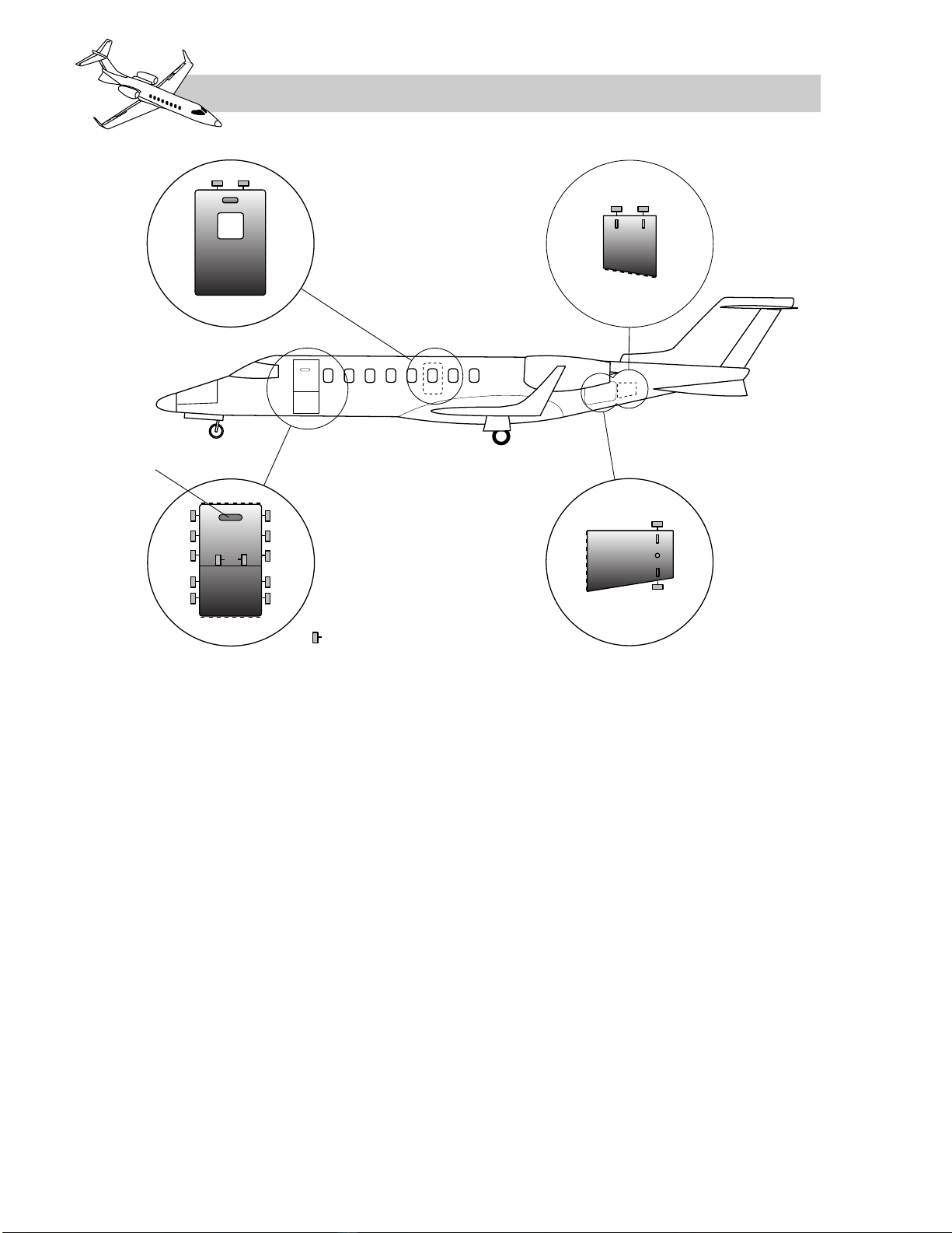
on either side of the tailcone section (Figure
1-16). These doors provide access to the air-
plane baggage compartment (left side) and to
the tailcone equipment bay (right side).
Access to the lighted and heated, unpressurized
baggage compartment, approximately 50 cubic
feet (capacity not to exceed 500 pounds), is pro-
vided through the external door on the left-hand
side of the tailcone section, just below the en-
gine nacelle. The 33 inch wide door is hinged
at the forward edge (Figure 1-16) and secured
by two latches and a security lock. A small
locking arm is provided at the top of the door
to rigidly hold the door in the open position.
LEARJET 45 PILOT TRAINING MANUAL
1-14
FOR TRAINING PURPOSES ONLY
FlightSafety
international
Figure 1-15. Windshield and Window Locations
Table of contents
Other FlightSafety Aircraft manuals


