FlightSafety TM-3-B User manual


NOTE: The portion of the text affected by the changes is indicated by a vertical line in the outer margin
of the page. Changes to illustrations are indicated by miniature pointing hands. Changes to wiring diagrams
are indicated by shaded areas.
Dates of issue for original and changed pages are:
Original...... 0....... September1999
Revision..... A...... January2001
Revised Section 3 of Touchscreen Ref.
Manual and made the Ops & Ref
manualsspecificfortheB737ratherthan
job specific
TOTAL NUMBER OF PAGES IN THIS PUBLICATION IS 214 CONSISTING OF THE FOLLOWING:
PAGE
NUMBER CHANGE
NUMBER* PAGE
NUMBER CHANGE
NUMBER* PAGE
NUMBER CHANGE
NUMBER* PAGE
NUMBER CHANGE
NUMBER*
Cover............... 0
A.................. 0
i................... 0
Operation Manual
Cover............... 0
ithruv.............. 0
1-1thru1-5.......... 0
2-1thru2-17......... 0
3-1thru3-27......... 0
4-1thru4-7.......... 0
Touchscreen Reference Manual
Cover............... 0
ithrux.............. 0
1-1thru1-5.......... 0
2-1thru2-10......... 0
3-1thru3-107........ 0
4-1thru4-6.......... 0
I-1thruI-3........... 0
G-1thruG-7......... 0
*Zero in this column indicates an original page.
LIST OF EFFECTIVE PAGES TM-3-B 737-IOS1-007
INSERT LATEST CHANGED PAGES. DESTROY SUPERSEDED PAGES.
FSI-SSD A
NT IOS Operation/Touchscreen

INTRODUCTION
The Instructor Operations Manual and the Touchscreen Reference Manual provide an instructor with
operating procedures for developing and conducting flight simulation sessons using the Instructor/Operator
Station(IOS).TheInstructor OperationsManualdescribeshardwarecomponents, andprovidesinstructions
for the operation of these controls and indicators. The Touchscreen Reference Manual describes software
components, and provides instructions for the operation of the touchscreens.
The Instructor Operation Manual and the Touchscreen Reference Manual for the IOS are written to be
used with the simulator specific Malfunction Document which is provided upon simulator delivery or
shortly thereafter.The MalfunctionDocument is uniqueto eachsimulatorand containsdetailedinformation
about the nature and qualities of aircraft malfunctions that can be inserted into training sessions. These
three companion documents are prepared to be general enough to be helpful in a variety of situations,
and to be useful for both the novice and experienced operator.
The IOS is a powerful, comprehensive tool that the instructor uses to conduct training sessions. These
manuals reflect this power and complexity. The manuals address all the capabilities available through the
IOS in reasonable detail; however, considering the complexity of the IOS and the various uses to which
it is put, a certain amount of practice and experimentation by the user is advised and will be necessary
to develop competency with the IOS.
TM-3-B 737-IOS1-007
FSI-SSD i Operation (NT IOS)
B737 JAN 2001


Table of Contents
SECTION 1 : INSTRUCTOR STATION OVERVIEW
1.1. INTRODUCTION ...............................................1-1
1.2. OVERVIEW....................................................1-1
1.3. GENERALSYSTEMDESCRIPTION...............................1-1
1.4. SIMULATORRELATEDDOCUMENTS............................1-3
1.5. HARDWAREFEATURES........................................1-3
1.5.1. ControlPanels..............................................1-4
1.5.2. Touchscreens...............................................1-4
1.5.3. Keyboard..................................................1-4
1.5.4. Printer....................................................1-4
1.5.5. WritingSurface.............................................1-4
1.5.6. Seats......................................................1-5
1.5.7. CockpitManagementMonitorSystem...........................1-5
1.5.8. Telephone .................................................1-5
1.6. SOFTWAREFEATURES.........................................1-5
SECTION 2 : DESCRIPTION OF CONTROLS AND INDICATORS
2.1. INTRODUCTION...............................................2-1
2.2. EXTERIORCONTROLSANDINDICATORS........................2-1
2.2.1. Access Ramp...............................................2-2
2.2.2. BackPorch................................................2-2
2.2.3. OnMotionWarningLamp....................................2-3
2.2.4. EmergencyLadder .........................................2-3
2.2.5. SimulatorEntrance .........................................2-3
2.2.6. PressureSensitiveMats.......................................2-4
2.2.7. OperationIndicators.........................................2-5
2.2.8. ExteriorEmergencyLight.....................................2-5
2.3. INTERIORCONTROLSANDINDICATORS ........................2-6
2.3.1. InteriorEmergencyLight.....................................2-6
2.3.2. Thermostat.................................................2-6
2.3.3. CompartmentLightingSwitch.................................2-7
2.3.4. RampControlSwitches ......................................2-7
2.3.5. MaintenanceLightingSwitch..................................2-8
2.3.6. ControlPanels..............................................2-8
TM-3-B 737-IOS1-007
FSI-SSD i Operation (NT IOS)
B737 JAN 2001

2.3.6.1. CommunicationsControlPanel............................2-9
2.3.6.2. Clock/Simulator Sound Control Panel .......................2-10
2.3.6.3. LightingControlPanel...................................2-11
2.3.6.4. HydraulicControlPanel..................................2-12
2.3.6.5. Freezes/Resets Control Panel ..............................2-13
2.3.6.6. MiscellaneousControlPanel..............................2-14
2.3.7. SmokeControlPanel ........................................2-15
2.3.8. CommunicationsJacks.......................................2-16
2.3.9. Keyboard/Mouse Jacks .......................................2-17
SECTION 3 : OPERATION
3.1. INTRODUCTION ...............................................3-1
3.2. INITIAL CONDITIONS ..........................................3-1
3.2.1. Walk Around Inspection......................................3-1
3.3. BRINGINGSIMULATIONUP.....................................3-2
3.3.1. BeginningOfSessionSimulatorSetUp .........................3-2
3.4. BRINGINGSIMULATIONDOWN.................................3-4
3.4.1. End-Of-SessionSimulatorReset................................3-4
3.5. CONTROLPANELOPERATION..................................3-5
3.5.1. Communications............................................3-5
3.5.1.1. VHFCOMMXMT......................................3-7
3.5.1.2. AUX#1ANDAUX#2..................................3-7
3.5.1.3. PILOT,CO-PILOT,andOBSERVERMONITOR.............3-7
3.5.1.4. INSTRUCTOR AUDIO and MAINTENANCE INTERPHONE . . 3-7
3.5.2. Clock/Simulator Sound Control Panel ...........................3-8
3.5.2.1. Clock.................................................3-9
3.5.2.1.1. ClockControls ....................................3-9
3.5.2.1.2. UsingTheElapsedTimeMeter.......................3-10
3.5.2.1.3. SettingtheClock(SeeFigure3-5).....................3-11
3.5.2.2. Simulator Sound ........................................3-12
3.5.3. LightingControlPanel.......................................3-12
3.5.3.1. ConsoleLightingControls................................3-12
3.5.3.2. DisplayControls........................................3-12
3.5.3.3. CompartmentLight......................................3-13
3.5.4. HydraulicControlPanel......................................3-14
3.5.4.1. ControlLoading........................................3-14
TM-3-B 737-IOS1-007
FSI-SSD ii Operation (NT IOS)
B737 JAN 2001

3.5.4.2. MotionSystem.........................................3-14
3.5.4.3. Reset.................................................3-15
3.5.4.4. HydraulicPowerOff ....................................3-15
3.5.5. Freezes/Resets ..............................................3-16
3.5.5.1. Position Freeze .........................................3-17
3.5.5.2. Total Freeze ...........................................3-17
3.5.5.3. Fuel Freeze ............................................3-17
3.5.5.4. Altitude Freeze .........................................3-17
3.5.5.5. Flight Freeze...........................................3-18
3.5.5.6. ApproachIAF..........................................3-18
3.5.5.7. TakeoffPoint ..........................................3-18
3.5.6. MiscellaneousControlPanel...................................3-19
3.5.7. SmokeControlPanel ........................................3-19
3.5.7.1. InstructorStartUp ......................................3-20
3.5.7.2. READY...............................................3-21
3.5.7.3. EmergencyExhaust .....................................3-21
3.5.7.4. UsingSmokeGeneratingControls..........................3-21
3.6. PRINTER......................................................3-21
3.6.1. PrinterControlPanel.........................................3-21
3.6.1.1. PrinterControlPanelDefinitions...........................3-22
3.7. INSTRUCTOR/OBSERVERSEATS................................3-24
3.7.1. SeatAdjustments............................................3-24
3.8. THERMOSTAT.................................................3-26
3.9. COMPUTERSYSTEMS..........................................3-27
SECTION 4 : EMERGENCY CONDITIONS
4.1. HAZARDS.....................................................4-1
4.1.1. Electrical Hazards ...........................................4-1
4.1.2. Motion Hazards.............................................4-1
4.1.3. Fire Hazards ...............................................4-2
4.2. STOPPINGTHESIMULATORINANEMERGENCY.................4-3
4.3. ALTERNATIVESTOEMERGENCYOFF...........................4-6
4.4. EVACUATINGTHESIMULATOR.................................4-7
TM-3-B 737-IOS1-007
FSI-SSD iii Operation (NT IOS)
B737 JAN 2001

List of Figures
SECTION 1 : INSTRUCTOR STATION OVERVIEW
Figure1-1.TypicalInstructorOperatingStation........................1-2
SECTION 2 : DESCRIPTION OF CONTROLS AND INDICATORS
Figure2-1.ExteriorViewOfSimulator ..............................2-1
Figure2-2.SimulatorFloorPlan(ViewFromTop).....................2-2
Figure2-3.EmergencyLadder......................................2-3
Figure2-4.ExteriorViewOfInstructorCompartment...................2-4
Figure2-5.ExteriorSimulatorIndicators..............................2-5
Figure2-6.SimulatorInteriorView..................................2-6
Figure2-7.RearSwitchPanel......................................2-7
Figure2-8.ControlPanelsLocation .................................2-8
Figure2-9.CommunicationsPanelLocation...........................2-9
Figure 2-10. Clock/Simulator Sound Panel Location ....................2-10
Figure2-11.LightingControlPanelLocation..........................2-11
Figure2-12.HydraulicControlPanel................................2-12
Figure 2-13. Freezes/Resets Panel Location ...........................2-13
Figure2-14.MiscellaneousControlPanelLocation.....................2-14
Figure2-15.SmokeControlPanelLocation...........................2-15
Figure2-16.CommunicationJacks..................................2-16
Figure 2-17. Keyboard and Mouse Jacks..............................2-17
SECTION 3 : OPERATION
Figure3-1.CommunicationsJacks ..................................3-6
Figure3-2.InstructorCommunicationPanelControls...................3-6
Figure 3-3. Clock/Simulator Sound Panel Controls......................3-8
Figure3-4.ClockOperation-ElapsedTimeMeter.....................3-10
Figure 3-5. Clock Operation - Setting the Clock........................3-11
Figure3-6.LightingControlPanelLocation...........................3-13
Figure3-7.HydraulicControlPanelOperation.........................3-15
Figure 3-8. Freezes/Resets Panel Controls.............................3-16
Figure3-9.MiscellaneousControlPanelOperation.....................3-19
Figure3-10.SmokeControlPanel...................................3-20
TM-3-B 737-IOS1-007
FSI-SSD iv Operation (NT IOS)
B737 JAN 2001

Figure3-11.PrinterandControlPanelLocation........................3-22
Figure3-12.PrinterControlPanel...................................3-23
Figure3-13.Instructor/ObserverSeatAdjustments......................3-25
Figure3-14.ThermostatLocation...................................3-26
SECTION 4 : EMERGENCY CONDITIONS
Figure 4-1. Remote Annunciator ....................................4-2
Figure4-2.EmergencyOff.........................................4-3
Figure4-3.RampControlSwitches..................................4-4
Figure4-4.EmergencyHydraulicOff................................4-5
Figure4-5.HydraulicControlPanelPushButtons......................4-6
Figure4-6.EmergencyLadder......................................4-7
TM-3-B 737-IOS1-007
FSI-SSD v Operation (NT IOS)
B737 JAN 2001

SECTION 1 : INSTRUCTOR STATION OVERVIEW
1.1. INTRODUCTION
The purpose of the Instructor Operating Station (IOS) is to provide the facility from which the instructor
can monitor, control, and direct the training environment to which the student is exposed. This manual
describes the Instructor Operating Station equipped with one 21" touchscreen and two 14" touchscreens.
The size and configuration of screens and terminals installed could change due to the availability of
equipment.
1.2. OVERVIEW
The Instructor Station is located in the simulator behind the cockpit on the left side. It consists of one 21
inch touchscreen, two 14 inch touchscreen, control panels, two recessed lights, air conditioning vents,
and other miscellaneous equipment. Figure 1-1 illustrates a typical IOS layout. The IOS functions as the
instructor’s interface with the simulator and the student. Additionally, this Instructor Station provides
maintenancefacilities likesoftwaredebugging,self-diagnostics,andcomputerdiagnostics.Theinstructor’s
tools are the touchscreens and control panels.
1.3. GENERAL SYSTEM DESCRIPTION
The IOS is composed of two systems: hardware and software. The hardware system is presented in the
first part of this manual. The screens themselves, through which most of the instructor’s interface with
the simulator is accomplished, are considered part of the software, and are presented in the Touchscreen
Reference Manual which is in the second part of this manual.
TM-3-B 737-IOS1-007
GENERAL SYSTEM DESCRIPTION
FSI-SSD 1-1 Operation (NT IOS)
B737 JAN 2001
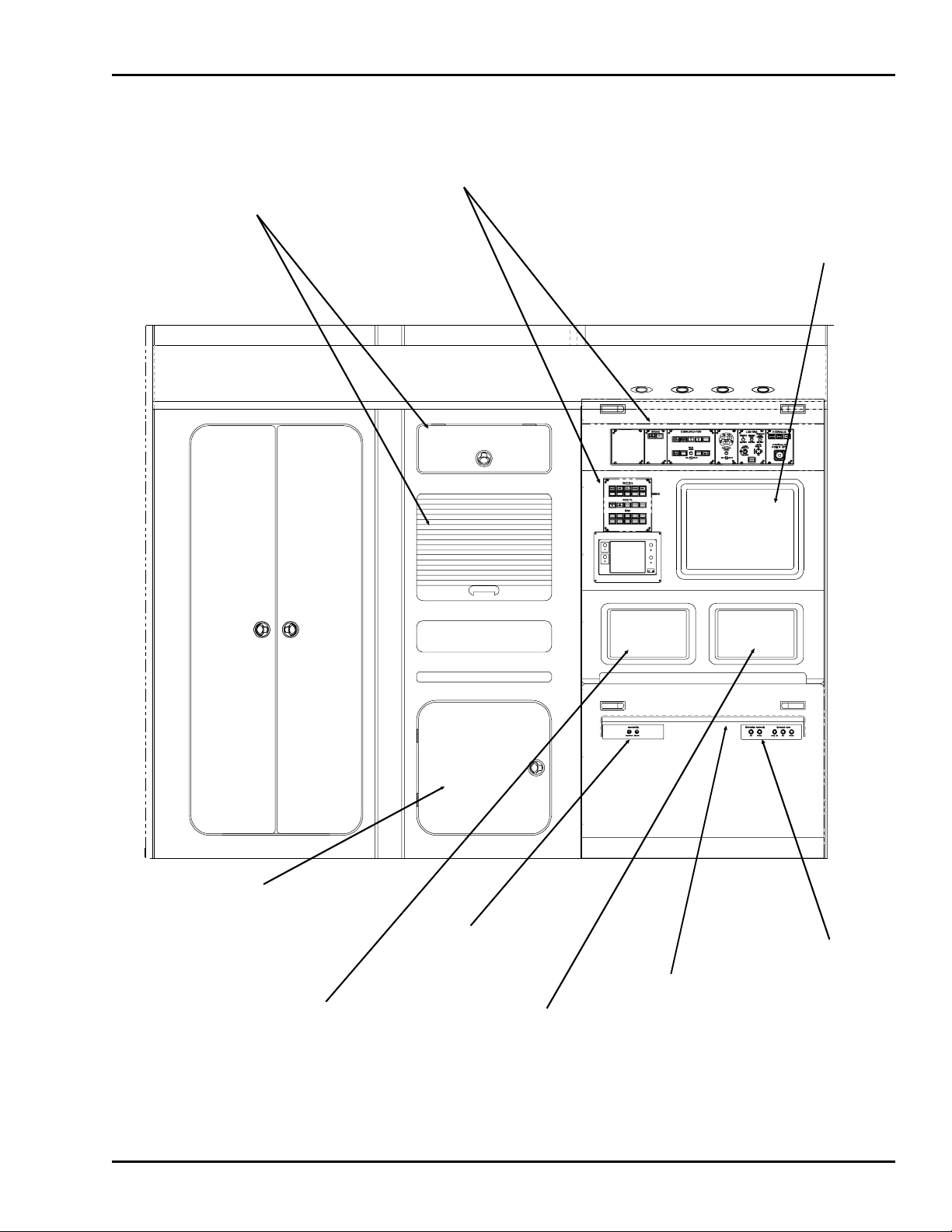
Control
Panels
Left
Touchscreen
Writing
Surface
Right
Touchscreen
Upper
Touchscreen
Cabinet containing
VCR and
Miscellaneous
CMMS Equipment
Bookshelf
and
Storage
Areas
Keyboard
and Mouse
Jacks Microphone and
Headset Jacks
Figure 1-1. Typical Instructor Operating Station
TM-3-B 737-IOS1-007
GENERAL SYSTEM DESCRIPTION
FSI-SSD 1-2 Operation (NT IOS)
B737 JAN 2001

In the hardware system, the main operator related components are:
•CONTROL PANELS:
COMMUNICATION HYDRAULIC
CLOCK/SIMULATOR SOUND FREEZES/RESETS
LIGHTING MISCELLANEOUS
SMOKE
•TOUCHSCREENS:
UPPER TOUCHSCREEN LEFT TOUCHSCREEN
RIGHT TOUCHSCREEN
•KEYBOARDS •WRITING SURFACE
•PRINTER •SEATS
•VIDEO RECORDER for CMMS •TELEPHONE
1.4. SIMULATOR RELATED DOCUMENTS
Additional manuals which the instructor should be familiar with are the IOS Touchscreen Reference
Manual, the Malfunction Document, the Touchscreen Printout Document, and the IOS Operation and
Maintenance Manual. The IOS Touchscreen Reference Manual is contained in the last half of this manual.
1.5. HARDWARE FEATURES
The touchscreens and panels located in the instructor compartment communicate with the off-board host
computer to allow the instructor to control and monitor simulated flight.
TM-3-B 737-IOS1-007
HARDWARE FEATURES
FSI-SSD 1-3 Operation (NT IOS)
B737 JAN 2001

1.5.1. Control Panels
There are several control panels on the instructor station. They include the Communication,
Clock/Simulator Sound, Lighting, Hydraulic, Freezes/Resets, and Miscellaneous control panels. This
simulator also contains a smoke generating system so a Smoke Control panel is also installed. The switches
located on these panels can be used, independently or in conjunction with other simulator systems, to
control and monitor simulation. Figure 1-1 shows the location of the control panels.
1.5.2. Touchscreens
There are three touchscreens located at the Instructor Station and are referred to as the upper touchscreen,
left touchscreen, and right touchscreen. The touchscreens are used by the instructor to monitor and control
the training session.
1.5.3. Keyboard
The keyboard for the touchscreens is stored in mounting brackets which are located in the storage closet
to the side of the Instructor Station console. The keyboard is mainly used by technicians to perform
computer related maintenance. Keyboard entries are not required for the control of the training session.
1.5.4. Printer
The printer is a color graphics printer and is usually located off board the simulator in the computer room.
This printer will print most screen displays from the touchscreens.
1.5.5. Writing Surface
The Instructor Station writing surface is a flat table top that can be stowed away when not in use.
TM-3-B 737-IOS1-007
HARDWARE FEATURES
FSI-SSD 1-4 Operation (NT IOS)
B737 JAN 2001

1.5.6. Seats
The instructor’s seat is located behind the cockpit, next to the Instructor Station console. It is cushioned
and has lockable adjustments. An additional seat is positioned to allow an observer to view the student’s
training.
1.5.7. Cockpit Management Monitor System
The simulator is equipped with the Cockpit Management Monitor System (CMMS). This system includes
a video and audio recording system that allows the instructor to record training sessions for later review.
The video recorder is usually located in a cabinet at the lower left of the instructor work surface and the
video camera is positioned between the pilot and co-pilot stations. The microphones are located within
the cockpit. Control of the CMMS is accomplished through the touchscreens and the video image may
be viewed on the upper monitor.
1.5.8. Telephone
The simulator is equipped with a telephone on the instructor station. The telephone can be connected to
the site’s telephone system which enables the personnel inside the trainer to communicate with personnel
outside the simulator while the flight training is in progress.
1.6. SOFTWARE FEATURES
The reactions of the simulator are controlled by programs stored in the host computer. Simulation software
interfaces with simulator hardware devices to generate an accurate representation of an actual flight.
Malfunctions, aircraft sounds, aircraft controls, visual scenes, and communications are controlled through
simulation software.
The touchscreens present displays which can be activated when simulation programs are running. The
instructor uses these screens to control and direct flight simulation.
TM-3-B 737-IOS1-007
SOFTWARE FEATURES
FSI-SSD 1-5 Operation (NT IOS)
B737 JAN 2001
SECTION 2 : DESCRIPTION OF CONTROLS AND INDICATORS
2.1. INTRODUCTION
Section 2 describes the location of the controls and indicators on the Instructor Station and those within
the instructor’s compartment that pertain to flight training and emergency procedures.
2.2. EXTERIOR CONTROLS AND INDICATORS
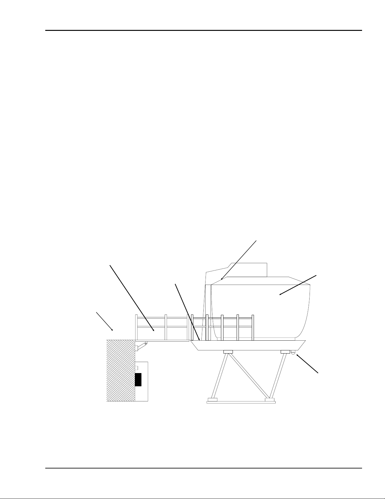
The following figures illustrate a typical layout of a FlightSafety Simulator. Figure 2-1 illustrates the
exterior view and Figure 2-2 illustrates the floor plan of a simulator.
AWRAMP.GEM
Access
Ramp
Instructor
Compartment
Back
Porch
Exterior
Platform
Cockpit, or
Student
Station
On Motion
Warning
Lamp
Figure 2-1. Exterior View Of Simulator
TM-3-B 737-IOS1-007
EXTERIOR CONTROLS AND INDICATORS
FSI-SSD 2-1 Operation (NT IOS)
B737 JAN 2001
2.2.1. Access Ramp
The access ramp is the walkway between the exterior platform and the entrance to the simulator. It has
a guard rail on each side and pressure sensitive mats covering the floor. Figure 2-2 illustrates the location
of the access ramp in the down position. The access ramp will raise vertically when the motion system
is enabled and lower when motion is deactivated.
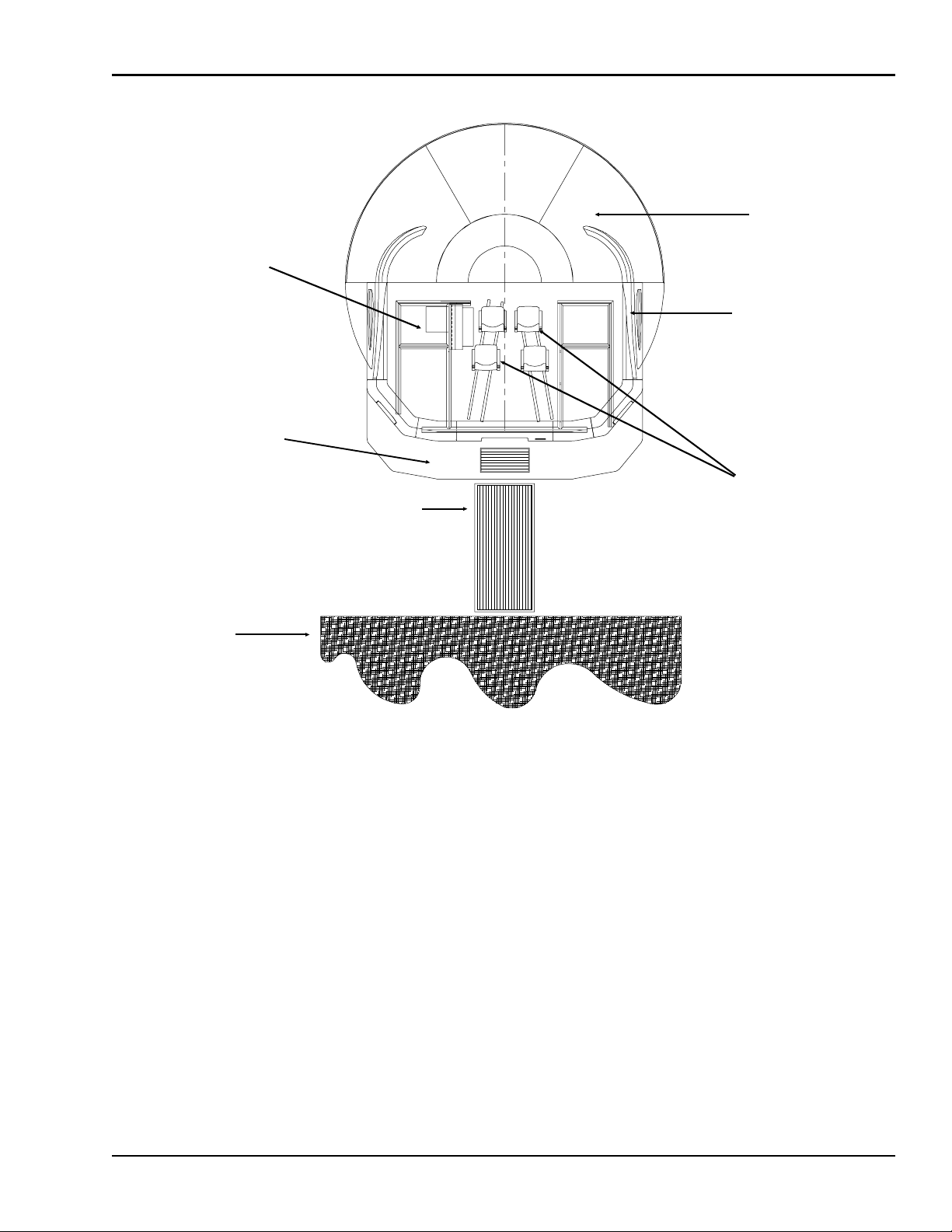
2.2.2. Back Porch
The back porch is the walkway surrounding the exterior of the simulator. The area directly in front of the
simulator entrance is covered with a pressure sensitive mat. Figure 2-2 illustrates the location of the back
porch of the simulator.
Instructor
Compartment
Cockpit
Area
Instructor
Station
Console
Instructor/
Observer Seats
Exterior
Platform
Access
Ramp
Back Porch
Figure 2-2. Simulator Floor Plan (View From Top)
TM-3-B 737-IOS1-007
EXTERIOR CONTROLS AND INDICATORS
FSI-SSD 2-2 Operation (NT IOS)
B737 JAN 2001

2.2.3. On Motion Warning Lamp
All FlightSafety Simulators are equipped with an on motion warning lamp to alert personnel that the
simulator isin motion. The warning lamp islocated on thesimulator frame andflashes when thesimulator’s
motion system is enabled. Figure 2-1 illustrates the general location of the on motion warning lamp.
2.2.4. Emergency Ladder
The Emergency Ladder is located in a compartment on the back porch of the simulator in front of the
door. It is used if the ramp does not work or if the simulator comes to rest in a position such that the
ramp would be of no use. See Figure 2-3. Procedures for using the ladder are found in Section 4, Paragraph
4.4., Evacuating The Simulator.
2.2.5. Simulator Entrance
The entrance to the simulator is located on the back of the instructor compartment. It has a hinged door
with a latch to keep the door closed during operation. See Figure 2-4. On some simulators, the motion
system cannot be enabled until the door is closed and latched.
Ladder
Compartment
Recessed On
Back Porch
Figure 2-3. Emergency Ladder
TM-3-B 737-IOS1-007
EXTERIOR CONTROLS AND INDICATORS
FSI-SSD 2-3 Operation (NT IOS)
B737 JAN 2001

2.2.6. Pressure Sensitive Mats
FlightSafety Simulators are equipped with pressure sensitive mats that are located on the access ramp and
directly in front of the door on the back porch of the simulator. The location of the back porch pressure
sensitive mat is illustrated in Figure 2-4. These are the mats with red rectangular emblems. These mats
house switches which are connected to the motion system. If a person is standing on the access ramp, the
motion system will not enable. If the motion system is enabled and a person steps onto the access ramp,
the motion system will shut down normally. If a person steps on the back porch mat while motion is
enabled, the motion system will abort and the access ramp will not descend. To lower the ramp, use the
Emergency Ramp Control switch.
Operation
Indicators
Pressure
Sensitive
Mat Exterior
Emergency
Light
Figure 2-4. Exterior View Of Instructor Compartment
TM-3-B 737-IOS1-007
EXTERIOR CONTROLS AND INDICATORS
FSI-SSD 2-4 Operation (NT IOS)
B737 JAN 2001
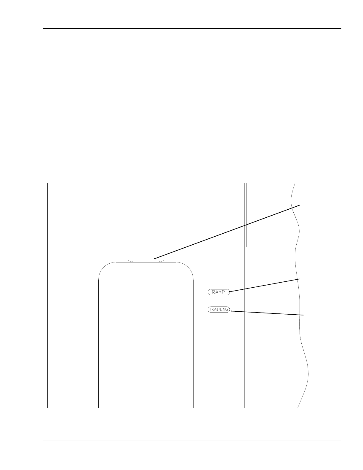
2.2.7. Operation Indicators
There are two rectangular Operation Indicators located near the entrance of the simulator. The Ramp
indicator flashes red when the access ramp is in motion and the TRAINING indicator illuminates red
when the control loading system is engaged. See Figure 2-5.
2.2.8. Exterior Emergency Light
The Exterior Emergency Light is located above, and outside the entrance to the simulator. It operates on
emergency battery power. The exterior emergency light illuminates automatically when the simulator
loses electrical power and remains illuminated for approximately 30 minutes or until power is restored.
SeeFigure2-5.
TRAINING
Indicator
Exterior
Emergency
Light
RAMP
Operation
Indicator
Figure 2-5.Exterior Simulator Indicators
TM-3-B 737-IOS1-007
EXTERIOR CONTROLS AND INDICATORS
FSI-SSD 2-5 Operation (NT IOS)
B737 JAN 2001
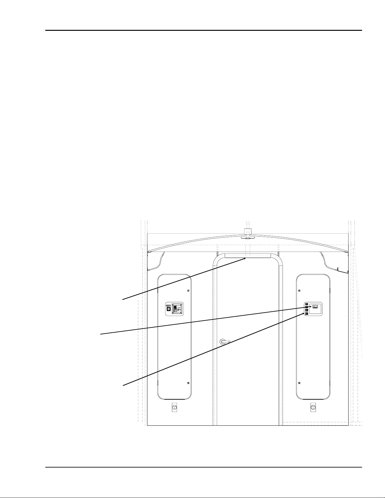
2.3. INTERIOR CONTROLS AND INDICATORS
See Figure 2-6 for the interior view of the simulator door and the controls and indicators located there.
2.3.1. Interior Emergency Light
The Interior Emergency Light is located inside the simulator above the entrance. It operates on emergency
battery power. The interior emergency light illuminates the interior automatically when electrical power
to the simulator is lost, and remains illuminated for approximately 30 minutes or until power is restored.
SeeFigure2-6.
2.3.2. Thermostat
The Thermostat is located on the rear wall adjacent to the simulator entrance, along with the Compartment
Floodlight Switch and Emergency Ramp Control Switch. See Figure 2-6. It is a programmable unit which
is operated as a home unit would be.
Interior
Emergency Light
(located in ceiling
above door)
Compartment
Floodlight Switch
and Emergency
Ramp Control
Switches
Thermostat
Figure 2-6. Simulator Interior View
TM-3-B 737-IOS1-007
INTERIOR CONTROLS AND INDICATORS
FSI-SSD 2-6 Operation (NT IOS)
B737 JAN 2001
Table of contents
Other FlightSafety Aircraft manuals


Popular Aircraft manuals by other brands


Grumman American
Grumman American AA-5 1975 owner's manual

Airplane Factory
Airplane Factory Sling-2 Pilot operating handbook

Air Creation
Air Creation SKYPPER evo 912 IS Pilot operating handbook

BOMBARDIER
BOMBARDIER SD3-60 Maintenance manual

Van's Aircraft
Van's Aircraft RV-12 Pilot operating handbook

Remos
Remos G-3 /600 Maintenance manual