Wowings Skua 1500 Instructions for use

- 1 -
Wowings Skua 1500
CONSTRUCTION MANUAL
Copyright 2005 Wowings
www.wowings.com

- 2 -
Thank you very much for purchasing the Skua 1500, hereto simply referred to as the S-15.
Although made primarily of soft EPP foam, this RC slope glider is still capable of causing
significant damage to property and serious personal injury or death to bystanders or yourself. Please
ensure that you fly this model in a safe and responsible manner and obey your local laws and
regulations. By building and/or flying the S-15 you assume all responsibility for any damage or
injury it may cause. As the kit manufacturer, Wowings accepts no liability for any damage or injury
caused by our products. If you do not agree to these terms, please contact your place of purchase
prior to commencing construction to arrange returning this kit for a refund.
Wowings’S-15 is legally protected as a registered design. Please do NOT copy any aspect of the
design, including its proprietary airfoil sections, even if only for private use. We have invested a lot
of time (and money) in developing this unique high performance glider and it is based on a
foundation of many years of flying and building experience. These kits are not mass-produced by a
large faceless corporation. We directly rely on, and sincerely appreciate, your support through the
purchase of our glider kits.
Now onto the fun stuff…First, please ensure that nothing is missing from the S-15 kit and that none
of the contents have been damaged. If anything is missing or damaged please contact your place of
purchase immediately to make arrangements for replacement parts to be supplied. Your S-15 kit
should contain the following:
•2 x EPP foam wing halves (each with two panels joined together)
•2 x lengths of 9mm diameter fiber glass tubular
•2 x length of carbon ribbon
•2 x lengths of spruce spar
•4 x lengths of balsa (two marked with outlines for trailing edge pieces and two for elevons)
•2 x steel pushrods with clevises attached
•1 x piece of coreflute marked with outlines for fins
•1 x blue plastic spar joiner
•1 x pack of Dubro nylon control horns (total of 2 control horns)
•1 x pack of Dubro E-Z connectors (total of 2 connectors)
To complete the kit you will require the following tools and supplies:
•Sharp trimming knife (large retractable disposable type is ideal)
•Sandpaper and sanding block, screwdriver, drill, pliers, hack-saw and ruler
•48mm (2”) wide cross-weave filament tape
•Covering material (eg. coloured packing tape or iron-on film such as UltraCote or Profilm)
•3M “Super 77” or 3M “Multi-Purpose” spray adhesive
•5 minute epoxy glue (eg. Selley’s Araldite)
•Goop/Goo glue (eg. Pacer’s Zappa-Dappa-Goo II or Second Wind’s Shoe Goo II) or
Polyurethane glue (eg. Selley’s Durabond, Gorilla Glue or Elmer’s ProBond) or 30 minute
epoxy glue (not ideal).
•Hot-melt glue –not essential
•Lead for optional ballast slugs and nose weight
The following radio equipment is recommended:
•Rechargeable receiver battery pack in flat configuration (4 x AA size cells).
•Receiver (minimum 2 channel)

- 3 -
•2 x servos. Either metal-geared micro/mini size servos (eg. GWS Micro 2BBMG or Hitec
HS-85MG) or standard size servos (eg. GWS S03TXF2BB or Hitec HS-311).
•2 x 100mm or 300mm servo extension leads
•If your transmitter doesn’t have a built-in elevon mixing function you will also need a
electronic elevon mixer (eg. DigiMix II)
Take a few minutes to have a quick read through this entire instruction manual prior to starting so
that you have an overview of the steps involved. Please don’t be tempted to deviate from these
instructions unless you are an experienced builder and are confident that your changes won’t
negatively affect the structural integrity or flying performance of the S-15. These instructions are
based in metric units but I have also tried to include the equivalent imperial measurement as much
as possible. For your reference, 1 inch (”) equals 25.4 millimeters (mm). An online version of these
instructions, with colour photos, is located on Wowings website at www.wowings.com .
SPAR INSTALLATION
Polyurethane (PU) glue is probably the best option for gluing in the wing spars. It foams up and
expands during the curing process and penetrates into the surrounding EPP foam creating a strong
tight bond without adding a lot of weight. However, if not used carefully it can create a mess and
possibly even ruin the wing. For this reason, these instructions will focus on using more fool-proof
glues instead. If you decide to try using PU glue for the first time, it’s best to experiment a little on
some scrap EPP before applying it to your wing. Ensure there’s a layer of waxed paper between the
wing and the bottom wing bed because the PU glue penetrates through the EPP easily. Be sparing
with the amount of PU glue used and wipe the spar with a damp cloth prior to gluing in place to
help the glue activate. Ensure that the wing is adequately weighted down in its beds while the glue
is curing.
1. Remove the foam wing cores from their
beds. Gently bend open the spar slot and
carefully remove the foam “noodle” from
the spar channel. Trial fit the 9mm carbon
spars to ensure that no bits of foam have
been left in the spar channel. They should
fit easily without the spar slot being forced
apart. Remove the spars and put them aside
to be used shortly.
2. Glue the two wing halves together using
hot-melt glue, a contact adhesive or spray
adhesive (epoxy is also OK but can
sometimes becomes a little brittle).

- 4 -
3. Locate the plastic spar joiner and place it
on top of the central wing join. Align so
that the spar joiner’s hole is centered over
the wing join line and that both ends are
centered on top of the spar channel.
4. Trace around the wing joiner with a pen
and then use a sharp utility knife to cut
along this outline all the way through the
foam. Push out the resulting foam plug and
put it aside to be used later.
5. Also trace the outline of the spar joiner on
a scrap piece of EPP (perhaps from the top
part of a wing bed) for possible use later.
6. Glue both 9mm spars into the spar joiner
using 5 minute epoxy glue. Ensure that
each spar is pushed all the way into the
spar joiner.
7. Gently bend open the spar slot and run a
bead of goop/goo glue (30 minute epoxy is
also fine but not quite as good) inside the
spar channels of both wing halves. Starting
at one wing tip, bend open the spar slot and
push the spar assembly into the spar
channel. Once the whole spar assembly has
been inserted, use a piece of dowel, or
back of a pen or pencil, to firmly push the spar assembly all the way down into the channel
so that the glue is forced up and around the spars, coating them entirely. This process can
also be helped by bending the wing chord-wise, temporarily opening and closing the spar
slot. Wipe off any excess glue.
8. Place the entire wing back into its foam beds and rest it on a completely flat hard surface
(eg. table or floor). We suggest removing the top portion of the wing beds by cutting along
the leading edge. Weight it down so that the wing is kept flat and completely snug with the
bottom curve of its foam beds. To avoid deforming the foam make sure the weights aren’t
too heavy and that they are spread fairly evenly. Bags of sand are ideal because they contour
to the top of the wing. Leave overnight (or as per glue’s instructions) in this position while
the glue fully cures.
WING ASSEMBLY
There are a couple of options here regarding the spruce drag spars (sub-trailing edge spars). If you
want to build your S-15 as light as possible they can be omitted entirely. As a “standard” build we
suggest at least attaching spruce drag spars to the outer panels’ sub-trailing edge. Attaching them to
the inner panel’s sub-trailing edge as well (prior to installing the balsa fixed trailing edge pieces)
increases strength even further with only a small increase in weight.
For those that like being a bit different, you also have the option of building the S-15 with a single
fin on a central boom instead of the standard dual fins (most robust). These instructions won’t detail
the single fin option but it’s a relatively simple matter of using the provided 5mm diameter carbon
tube as a boom embedded into the bottom surface of the wing (into both the balsa trailing edge and

- 5 -
foam) approximately 100mm (4”) forward from the trailing edge. You may wish to substitute the
coreflute fin for a balsa one (not provided) if choosing this option.
9. Locate the two lengths of wooden (spruce) drag spars.
10. If you wish to install drag spars to the inner wing panels, cut off the appropriate length
(approximately 320mm) from each length of spruce (not off the same piece).
11. Use epoxy to glue these pieces of spruce to
the inner wing panels and hold in place
with masking tape while curing. If using 5
minute epoxy just do one side at a time so
you have adequate working time to get
them aligned and secured properly.
12. Once the glue has cured, sand off the outer
ends of the spruce so that they’re angled in
line with the outer wing panels foam sub-
trailing edge.
13. Locate the two balsa trailing edge pieces.
Cut out along the lines marked. Place them
up against the centre panels’ foam trailing
edges to make sure they fit nicely together in the middle. The bottom surface of the balsa
trailing edges is the one that had the cut-out lines marked on them (and the surface that
meets the leading edge at a 90 degree angle). When butted up against the foam trailing edge,
the bottom surface of the balsa trailing edge piece should form a continuation of a straight
line starting from the from the rear half of the foam airfoil shape.
14. Once you are happy that they will fit nicely, round off the top and bottom edges of the outer
end only of each balsa trailing edge piece (not where they join together) to make covering
easier later on.
15. Use 5 minute epoxy to glue one of the balsa trailing edge pieces to the drag spar (or the
foam if no drag spar was installed). Hold in place with masking tape and use a straight edge
(ruler) held against the rear section of the bottom of the wing and the bottom of the balsa
trailing edge to ensure correct alignment (straight line). Once the glue has cured repeat this
process for the second balsa trailing edge piece, also end gluing to the first piece where they
meet at the center of the wing.
16. Once the glue has cured, mark out lines on
the fixed balsa trailing edge that continue
about 50mm (2”) in from both ends in line
with the outer panels’ foam trailing edge.
Mark out a second set of lines parallel to
these with the thickness of the spruce drag
spar material (3mm, or 1/8”).
17. Use a saw to cut along the forward line and
then widen to the correct width with a
knife and/or sandpaper.
18. Locate your two remaining lengths of
spruce drag spar and trial fit them to the
foam trailing edge of the outer wing panels
and into the slots you’ve created in the balsa fixed trailing edge. Adjust the slots as
necessary to form a nice snug fit.
19. Mark and cut the two pieces of spruce to length so that they stop flush at the wingtips.

- 6 -
20. Once you’re happy that everything will fit
together properly, use epoxy to glue these
pieces of spruce to the outer wing panels
and into the slots in the fixed balsa trailing
edge and hold in place with masking tape
while curing. If using 5 minute epoxy just
do one side at a time so you have adequate
working time to get them aligned and
secured properly.
21. Once the glue has fully cured, trim and
sand off any glue along the glue lines of
the drag spars and balsa trailing edge and
any parts of the balsa trailing edge or drag
spars that are protruding above the surface of the foam (mainly along the outer wing panels
towards the wing tips). The aim is to create a smooth transition from the foam portion of the
wing to the spruce and balsa trailing edge of the wing so that there’s a nice continuation of
the slightly reflexed airfoil shape. This is important both from an aerodynamic point of view
and for aesthetics (so the transition is not noticeable once the model is covered).
22. Locate the two balsa elevon pieces and cut out along the lines marked. You will have a left
and a right elevon, each orientated so that their narrower end is at the wing tip.
23. Using a sanding block, sand a 45 degree
bevel along the leading edge of each
elevon, with the 45 degree opening on their
bottom surface (ie. they’ll be hinged on top
surface).
24. Round off the top and bottom edges of
each end of both elevons to make covering
easier. Put them aside to be installed later.
25. Round off the top and bottom edges of
each wing tip using a sharp knife. You may
also wish to round the leading edge corners
of the wing tips when viewed from above.
26. Locate the piece of coreflute supplied in
the kit and cut out the two fins as marked.
27. Mark out where the slots for the fins will
go on the wing. You’ll need a slot 2mm to
3mm (3/32” to 1/8”) wide and 75mm (3”)
long, with the rear of the slot starting
40mm (1 1/2”) forward of the rear edge of
the outer panels spruce drag spar (edge of
foam if no drag spar installed). It should be
positioned just slightly inboard of the panel
join line.
28. The area of the wing behind the fin slots in
reinforced with the supplied carbon ribbon.
Cut the length of carbon ribbon exactly in
half for use as two reinforcement spars.

- 7 -
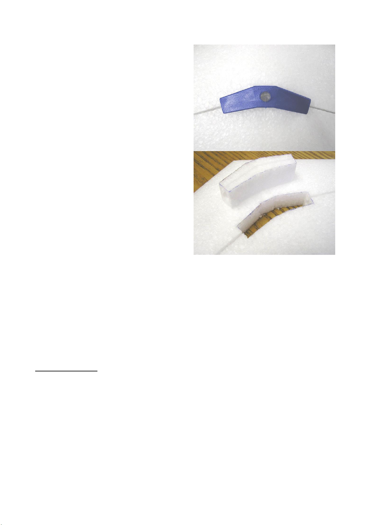
29. Mark out where the carbon reinforcement ribbons are to be placed. They should be centered
approximately 25mm (1”) behind the marked location for the fin slots and aligned so that
each one is roughly parallel with the main spar on their half of the wing.
30. Cut vertical slits about 10mm (3/8”) deep for the carbon ribbon along the lines marked and
test fit to ensure correct depth (they should be flush with the top surface of the wings at
either end).
31. Once you’re happy that the carbon reinforcement ribbons fit nicely, glue them in place with
thin CA glue or epoxy. It’s a good idea to place the wing back in its beds while the glue
cures to ensure correct alignment.
32. Use a light-weight spackle/filler to fill in any voids above the carbon reinforcement ribbons
if required. Then sand smooth to the contour of the wing.
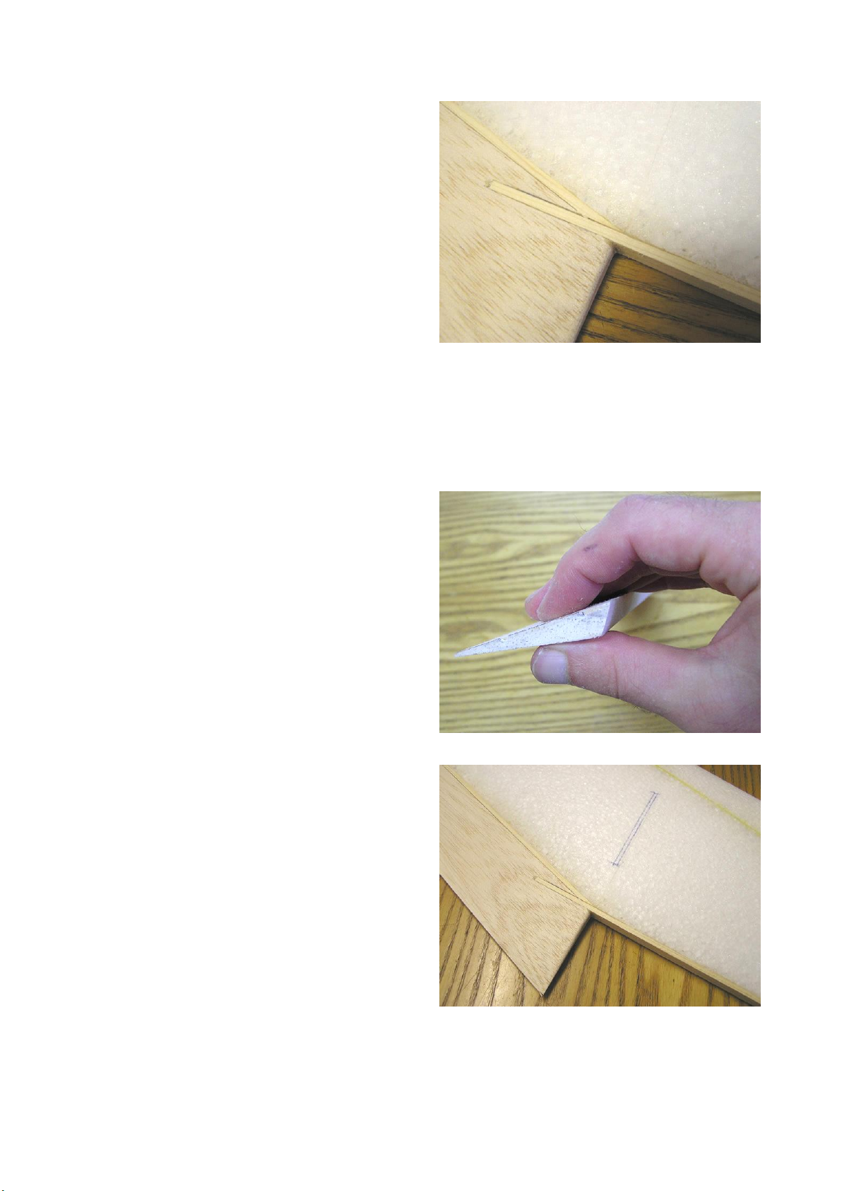
33. Now cut out the fin slots along the outlines you marked earlier. Cut all the way through the
wing with a very sharp blade, being extra careful to keep the cuts vertical. Poke out the foam
from the slots with the end of a ruler or a metal pushrod.
34. Test fit the fins to ensure that they fit tightly into the foam in a vertical position and that
their trailing edge is in line with the wing’s trailing edge (NB: If drag spars were installed on
the inner panels, the balsa trailing edge will need to get trimmed a little to match the width
of the elevons). When pushed all the way down, the fins should butt up against the top
surface of the wing. Trim the bottom edge of the fins to match the wings contour if
necessary. Once you’re happy with the fit remove the fins and put them aside for later.
BALLAST TUBE INSTALLATION
This section of the instructions are for those with a S-15 ballast kit. These can be purchased
separately in addition the standard S-15 kit and contain the following:
•1 x length of 9/16” (14mm) diameter brass tube
•1 x length of 1/2” (13mm) diameter brass tube
•1 x length of pine dowel
•1 x EPP foam “jacket” for brass ballast tube
Installation of a ballast tube is optional but recommended so as to achieve optimum flying
performance in a wider range of conditions. Ballast weight is added to a glider to make it fly faster
through the air. The amount of ballast weight able to be added is dependent on the amount of lift
being generated by the slope you’re flying from. Increasing weight is particularly useful in windy
conditions to maintain good penetration into the wind. Ballast adjustment is also crucial for
competitive racing, enabling the glider’s wing-loading to be optimized for any given set of flying
conditions.
For “dynamic soaring” (DS) however, one should aim for as little ballast weight as possible. Extra
weight should only be added if it’s needed for penetration through turbulence and retention of
energy through the circuit. Unlike “normal”slope soaring in which the airfoil relies on gravity
(weight) as its fuel for generating speed, DS simply relies on differential airspeeds and gravity
becomes insignificant as a source of acceleration. Extra weight during DS increases the in-flight
stresses on the airframe and decreases the efficiency with which the airfoil generates the necessary
lift to counteract the centrifugal forces of its elliptical circuit, both of which lead to a lower potential
top speed and a slower rate of acceleration.
The ballast tube must be positioned exactly on the finished glider’s CG position to avoid any
balance changes with ballast adjustment, so only go ahead with the installation at this point if

- 8 -
you’re confident you’ll be happy sticking with the CG placement we recommend. It may be safer to
leave the ballast tube installation until after your first test flight so that you can first arrive at the
exact CG location that best matches your personal preferences. The downside of leaving the ballast
tube installation until last is that you’ll need to cut through the filament tape and covering you’ve
applied and then repair this with a sufficient patch of filament tape and covering. The choice is
yours. These instructions outline the method for installation at this stage in the construction. If you
will be installing the ballast tube later, don’t forget to ensure that the area is kept free of the radio
equipment and its wires.
The brass tubes provided jump two steps in size. We figured it’s better to put up with a little rattle
rather than have lead slugs that get jammed in the ballast tube and/or need to get filed or sanded
down to fit easily. If you’d prefer not to have a rattle, simply purchase a 12” length of K&S brass
tubing with a 17/32” diameter (#140) for use as the ballast tube instead of the 9/16” one provided.
If you can get your hands on a ready-made ballast kit of suitable size (9/16” max. diameter ballast
tube) we highly recommend doing so instead of trying to make this yourself. Lead is a hazardous
substance to work with (particularly the fumes during melting and fine dust during grinding) due to
its toxicity so appropriate precautions should be taken if you decide to proceed with the following
steps to make the ballast system yourself.
35. Locate the 1/2” (13mm) diameter brass tube. This can be used as the housing for your lead-
filled “slugs” (cylindrical sections). Mark out the tube so that it is divided into 8 equal
lengths each measuring 1 1/2" (38mm).
36. Use a hack-saw to cut the tube into 8 equal sections, seal of one end of each one with
masking tape and then push into some damp sand or soil to hold them securely upright.
37. Melt some lead in a used tin can. Lead
fumes are extremely toxic so ensure this is
done outside well away from other people
and wear an appropriate respirator.
38. Carefully pour the molten lead into the 8
tubes until they are all full and then leave
them to cool.
39. Grind/sand the ends of these lead ballast
slugs so that they are all exactly the same
size and so that there are no sharp edges.
Lead dust is extremely toxic so ensure an
appropriate respirator is worn and
thoroughly clean away and dispose of the
lead dust afterwards.
40. Locate the 1/2” (13mm) diameter pine dowel and cut into lengths exactly the same size as
the lead ballast slugs. You will only require 6 of these.
41. Sand to size and smooth as per the ballast slugs.
42. Locate the 9/16” (14mm) diameter brass tube. This is to be used as the ballast tube to
accommodate the lead slugs when ballast is required.
43. Load up the ballast tube with all 8 lead slugs and measure/mark how much needs to be
trimmed off the ballast tube to bring it in line with where the lead slugs finish. Then cut the
ballast tube to the appropriate length with a hack-saw.
44. Locate the foam “jacket” for the ballast tube, remove its foam “noodle” and trim it to the
same length as the ballast tube.

- 9 -
45. Cover both openings of the ballast tube with a little masking tape to prevent glue entering
the tube and then glue the ballast tube into its foam “jacket” using epoxy or PU glue.
46. The ballast tube needs to be positioned
EXACTLY on the finished glider’s centre
of gravity (CG). This is to ensure that the
addition of ballast weight does not alter the
glider’s balance at all. Accurately measure
185mm (or your preferred CG location)
back from the nose and draw a line on the
BOTTOM surface of the wing at right
angles to the centre panel join line at this
point.
47. Mark the halfway point on the ballast
tube’s foam jacket.
48. Position the ballast tube (in its foam
jacket) on the bottom surface of the wing
so that its channel opening is directly on
top of the CG line you drew and also so
that it is centered over the centre wing
panel join line.
49. Trace around the ballast tube’s foam jacket
with a pen and then cut along this outline
all the way through the wing and remove
the resulting foam plug.
50. Test fit the ballast tube’s foam jacket into
this cut-out to ensure it fits snugly. Adjust
if necessary.
51. Use PU glue (or epoxy) to glue the ballast
tube and foam jacket assembly into the wing so that the side of the foam jacket with the
ballast tube channel opening is completely flush with the bottom surface of the wing. Place
the wing in its beds while the glue is curing to ensure correct wing alignment.
52. Once the glue has cured, cut off the excess foam from the foam jacket so that it is also flush
with the top surface of the wing. Sand smooth to form a clean continuation of the airfoil
shape.
53. Mark out an area for a hatch to access the
ballast tube that is approximately 30mm x
45mm (1 1/8” x 1 3/4”) and directly next
to one end of the ballast tube on the bottom
surface of the wing.
54. Cut along this outline all the way through
the wing and then remove the resulting
foam plug. Mark a line vertically up the
foam plug’s front side for later reference.
55. Mark out the required depth
(approximately 18mm or 11/16”) of the
access cavity on the foam plug on all sides
and then cut the foam plug in two along
this line.

- 10 -
56. Use hot-melt glue or spray adhesive (or any other glue of choice) and glue the thinner piece
of the plug back in place so it’s flush with the top surface of the wing. This forms the base
of the ballast tube access cavity.
57. Angle the side of the remaining piece of the foam plug that is furthest away from the ballast
tube. This is to provide clearance to move when it’s hinged later on.
58. Smear the inside of the cavity and the sides of the foam plug, except the one that forms the
bottom surface of the wing, with a thin layer of goop or epoxy. This is to help with
durability during opening and closing of the hatch and ballast adjustments. Once the glue
has cured on both the foam plug and the cavity, push the plug back into place. It should sit
flush with the bottom surface of the wing.
59. Cut a length of spruce (you should have
some scrap pieces leftover from the drag
spars) to about 40mm or 50mm (1 1/2” to
2”) in length and embed into the foam at
the opposite end of the ballast tube to the
access hatch. Glue in place with epoxy so
it’s flush with the bottom surface of the
wing and hard up against the end of the
ballast tube. You can also face the side of
the ballast access lid/plug with a piece of
spruce as well. This is to help prevent the
lead slugs from penetrating into the foam
during rough “landings” (ie. cartwheels).
RADIO INSTALLATION
You can use either standard size servos or metal-geared mini/micro size servos for the S-15.
Standard servos have the advantage of being cheaper, stronger and usually develop less “slop”
(free-play) in their gears. However, they are substantially heavier so the model will require more
nose weight to balance (because the servos are behind the CG), increasing its all-up weight further
(by up to about 100 grams). Their bigger size also necessitates that they’re positioned only a little
outboard from the wing panel join line (fin slot) so that they can fit into the thickness of the wing.
This presents the possibility of the elevons twisting a little under extreme aerodynamic loads. The
smaller servos on the other hand can be positioned further outboard so that the elevons are actuated
close to their aerodynamic center and their lighter weight reduces the all-up weight of the model
significantly. However, you must ensure they’re rated to provide adequate torque (at least
2.5kg.cm) and have metal gears for appropriate durability. We tend to favor the use of metal-geared
micro servos (mainly because of the weight issue) but the choice is entirely yours.
60. Gather together all the radio equipment
you plan to install into the glider and test
that it is working properly. If your receiver
and transmitter batteries are not fully
charged, charge them now.
61. Place your receiver’s flat 4xAA size
battery pack on top of the wing
immediately in front of the blue spar
joiner. Trace around it with a pen and then
cut around this outline all the way through

- 11 -
the foam. Remove this foam plug and draw a line vertically up its front side for later
reference.
62. Hold the side of your battery pack against the side of the foam plug so that it is centered and
trace lines to mark out the thickness of your battery pack. Repeat this for all four sides and
then cut off a bottom slice (base) and a top slice (lid) along these outlines. Mark the top of
the slices with an “x” for later reference and discard the remaining piece of the plug.
63. Using hot-melt glue (best), spray adhesive (sprayed into a puddle and then spread on) or 5
minute epoxy (not ideal), glue the base slice back into the bottom of the battery cut-out hole,
creating a base for the battery recess. Use the markings you made to orientate it correctly,
ensuring a perfect fit. Put the foam lid aside for later use.
64. Position your receiver within the area
between spar joiner and the ballast tube
location and to one side of the central wing
join (a recess for electronic elevon mixer
and/or excess length of leads will be
created on the other side later). Trace
around the receiver with a pen and then cut
out along this outline all the way down
through the foam. Remove this foam plug
and mark its front side with a vertical line
for later reference.
65. Decide whether you want to mount your
receiver flush with the top surface of the
wing or embed it beneath the surface. Base this decision on the layout and size of your
receiver and whether you intend to use a switch or plug the battery plug directly into the
receiver. I personally usually use receivers that have the plug sockets on the top surface (and
preferably the crystal as well) and mount them flush with the top surface of the wing. This
means the servo plugs are then sticking up above the wing’s surface (adding a little drag and
ugliness), but it is then simple and convenient to just plug in and take out the battery lead to
turn it on and off and gain easy access for charging.
66. Hold the side of your receiver against the side of the foam plug in the desired position (eg.
flush with the top surface) and trace the line(s). Repeat this for all four sides and then cut off
a bottom slice along this outline, and a top slice if you’ve decided to have your receiver
embedded below the surface. Mark the top of the slice(s) with an “x” for later reference and
discard the remaining piece of the plug.

- 12 -
67. Glue the bottom slice of the foam plug into the bottom of the receiver cut-out hole forming a
base for the receiver recess. Use the marks on its front side and top to orientate it correctly,
ensuring a perfect fit. If you have a top slice, put it aside for later use as a lid over the
receiver.
68. Next are the servo recesses. If you’re using micro or mini sized servos (metal-geared), we
suggest positioning them about 125mm (5”) outboard of the wing panel’s join line (fin slot).
If standard size servos are used they should be positioned about 15mm (9/16”) outboard
from the wing panel join line (fin slot). In either case the servos should be positioned so that
their control arm is on the outboard side.
69. Mark a line parallel to the wing panel join line at the appropriate distance outboard (125mm
or 15mm). At this area draw another line that is parallel to the spar and 5mm (3/16”) back
from the edge of the spar slot opening.
70. Decide whether you want to remove your
servos’ mounting lugs. These are generally
not required for foam gliders and their
removal makes mounting into foam a little
simpler and also enables the servos to be
positioned a little further forward. Base
your decision on the likelihood of
requiring the mounting lugs on the servos
for a different style of model in the future
and the availability and expense of
replacement servo cases.
71. Lay your servo on top of the wing so that
one of its sides is on the line you marked
parallel to the wing join and one of its
opposite corners (or servo mounting lugs)
is touching the line parallel to the spar slot.
Trace around the servo and then cut around
this outline with a sharp knife all the way
down through the foam. Push out the foam
plug and mark with a vertical line up its
front side for later reference.
72. Hold the side of your servo against the side
of the foam plug flush with the top surface
of the wing and trace out a line. Repeat this
for all four sides and then cut off a bottom
slice along this outline. Mark the top of the
slice with an “x” for later reference and discard the remaining piece of the plug.
73. Glue the bottom slice of the foam plug into the bottom of the servo cut-out hole forming a
base for the servo recess. Use the marks on its front side and top to orientate it correctly,
ensuring a perfect fit.
74. Repeat this process for the second servo recess on the other side of the wing.
75. Mark out the area next to the servo recess required to accommodate the servo arm and its
movement. It will be about 10mm (3/8”) wide by 20mm (3/4”) long. Cut out a triangular
shaped wedge down to the depth of the servo recess’s floor.
76. Repeat for the second servo recess on the other side of the wing.
77. Mark out an area next to the receiver to accommodate the excess length in the battery and
servo leads. An area approximately 30mm by 40mm (1 3/16” by 1 9/16”) is usually plenty.

- 13 -
Cut out a foam plug using the same method used for the receiver and servo recesses and
glue back in a 5mm to 10mm (3/16 to 3/8”) slice to form a base. Keep the remainder of the
foam plug for later use.
78. Cut slits into the top surface of the wing to accommodate the battery lead and servo leads.
The receiver antenna should be kept a little clear (and avoid any crossing if possible) of the
servo leads, battery leads and spar to avoid possible interference with the radio signal from
the transmitter. Cut a slit for the receiver antenna that loops around and then runs up about
25mm (1”) in from the foam trailing edge of one of the wing halves.
79. Fit the battery pack, receiver and servos into their recesses. Plug everything together and test
that it is working correctly. Make sure the servo arms are centered in the correct position
when the transmitter in on and its trims are neutral. The servo arms should be pointing
directly upwards, or leaning just slightly rearwards. Unscrew the servo arms and adjust if
required. Also check for correct direction of servo travel. Viewed from above, when your
transmitter’s elevator stick is pulled back for “up” control, both servo arms should move
forwards (towards the leading edge of the wing), and both servo arms should move
backwards when “down” control is applied. When your transmitter’s aileron stick is moved
to the right for “right roll” control, the right servo arm should move forwards and the left
servo arm backwards, and opposite when “left roll” control is applied.
80. Perform a “range check” for your radio equipment now. You should be able to control the
servos smoothly from 10 paces away with your transmitter’s aerial retracted (not extended at
all).
81. Once you are satisfied that your radio equipment is functioning correctly it’s time to start
building it into your glider. Soon retrieval of radio equipment will require surgery on your
glider so it is best to make any necessary adjustments or repairs now. Also keep in mind that
you will need to have access to a means of charging your receiver’s battery pack once it is
embedded into the glider. This can be by means of a special switch with charging socket or
as simple as having access to the battery pack’s plug (perhaps just having it plug into an
exposed socket of your receiver).
82. Coil up the excess length in the leads and insert them (along with the electronic elevon
mixer if used) into the recess you made next to the receiver. Slice off an appropriate
thickness from the top of the remains of this foam plug to form a lid and glue it in place
flush with the top surface of the wing.
83. Glue the battery recess’lid in place over the battery pack so it’s flush with the top surface of
the wing.
84. If you chose to embed your receiver below the wing surface, glue in the top slice from your
receiver’s foam plug now so that it is flush with the top surface of the wing.
85. Measure the distance from the bottom of the spar joiner to the bottom surface of the wing at
both the centre and the ends of the joiner. Cut a slice of the appropriate thickness from the
bottom of the spar joiner’s foam plug and glue it in place.
86. Repeat for the gap between the top of the spar joiner and the wing’s top surface. You may
want to use the scrap piece of EPP you marked out earlier (step #5) so that you don’t have
the gap from the spar slot.
87. Cut and/or sand off any excess glue from around the foam plugs so that they’re all flush
with the surface of the wing.
TAPING & COVERING
These instructions are based on using 48mm (2”) wide strapping tape with cross-woven fiberglass
filaments, hereto referred to simply as “filament tape”. The instructions outline the process of

- 14 -
covering with 48mm (2”) wide coloured polypropylene tape due to its simplicity and low cost.
Those who wish to spend a little extra money and take a little extra care can use a variety of other
covering materials such as Ultracote, Oracover and Profilm. These iron-on coverings provide a
much nicer finish and a little more strength but are a bit trickier to apply correctly. If using an iron-
on covering be sure not to use too high a heat or it may deform (melt) the foam. Also be careful not
to introduce any warps or twists into the wing when shrinking the covering. 3M Super 77 (“multi-
purpose”) spray adhesive is required regardless of the covering method used and is hereto referred
to simply as “spray adhesive”.
88. Thoroughly remove all dust from the glider and your work area.
89. Use masking tape to mask off any exposed radio equipment that you don’t want to get
sprayed with glue.
90. Go outside and spray the entire bottom surface of the wing with adhesive and then place it
upside down on a cardboard box (or anything else to keep it up off your work surface). Let
the spray adhesive dry for about 5 minutes (or until aggressively tacky).
91. Now it’s time to apply the filament tape. This provides essential tensile strength to the EPP
foam wing and helps to keep the glider rigid during flight. For each piece of tape applied,
overhang the wing by 25mm to 50mm (1” to 2”) and wrap around to the opposite surface of
the wing. When a piece ends at the balsa trailing edge you can just cut if off flush with the
edge (don’t wrap around). Rub each piece that is laid down with some fine sandpaper to
remove any release agent from the tape’s backing for better adhesion of subsequent layers of
filament tape, spray adhesive and/or covering. Thoroughly wipe off any dust that is created
each time.
92. Working on the bottom surface of the wing (that you just sprayed), lay a length of filament
tape along the spar line and continue along to the opposite wing half’s leading edge. Repeat
for the other wing half.
93. Lay a length of filament tape across the inner panels along the CG line (ballast tube
location) to form an “A” pattern with the previously laid filament tape.
94. Apply strips of filament tape to the wing in a crisscrossing pattern as per illustration.
95. Go outside again and spray the entire top surface of the wing with spray adhesive. Let dry
for about 5 minutes (or until aggressively tacky).
96. Apply filament tape patches over the servos and receiver (if mounted flush with the top
surface) to hold them securely in place.
97. Working on the top surface of the wing (that you just sprayed), lay a length of filament tape
along the spar line and continue along to the opposite wing half’s leading edge. Repeat for
the other wing half.

- 15 -
98. Lay a length of filament tape across the inner panels along the CG line (ballast tube
location) to form an “A” pattern with the previously laid filament tape.
99. Apply strips of filament tape to the wing in a crisscrossing pattern as per illustration (same
as bottom surface).
100. Locate the elevons you prepared
earlier and spray their bottom surface with
spray adhesive. Also spray the bottom
surface of the wing’s outer panels along
the foam trailing edge. Let dry for 5
minutes (or until aggressively tacky).
101. Cut a length of filament tape in half
lengthways and cut into six 65mm (2 1/2”)
long strips.
102. The balsa elevons are orientated so
that their narrower end is at the wing tip.
Position one of the elevons so that there is
a 2mm (3/32”) gap between its end and the
end of the fixed balsa trailing edge and
rotate it around so that it’s lying upside
down on top of the wing with its leading
edge in line with spruce drag spar. Use the
65mm (2 1/2”) long by 25mm (1”) wide
strips of filament tape to attach the balsa
elevon to the foam wing by wrapping
around pieces at either end and in the
middle of the elevon.
103. Repeat this process for the second
elevon.
104. Now rotate the elevons back
around so that they’re in their correct
position, butted up against the foam trailing edge with the 45 degree beveled opening at the
bottom.
105. Spray the top of both balsa elevons and the rear portion of the adjoining foam sub
trailing edges with spray adhesive. Let dry for 5 minutes.
106. Lay a strip of cross-weave filament tape down the entire hinge line of one elevon on
the top surface, positioned so that 1/3 of its width is on the elevon and 2/3 on the foam.
107. Repeat for the second elevon.
108. Spray the bottom surface of the wing along the wing’s center join line and each wing
tip with spray adhesive. Let dry for 5 minutes (or until aggressively tacky).
109. Lay a strip of filament tape along the centre chord of the wing, overlapping the panel
join line by about 12mm (1/2”). Lay another strip towards the other side of the join line,
overlapping the first by about 25mm (1”) so the overlap is centered over the panel join line.
Split and wrap around at the leading edge and cut off flush with the trailing edge.
110. Lay a strip of filament tape chord-wise (LE to TE) at each wing tip. Split and wrap
around at the leading edge and cut off flush at the trailing edge of the elevon.
111. Spray the top surface of the wing’s center join line and each wing tip with spray
adhesive. Let dry for 5 minutes (or until aggressively tacky).
112. Lay chord-wise strips of filament tape on the top surface at the wing’s center and
wing tips as per the bottom surface.

- 16 -
113. Spray the leading edges of the wing with spray adhesive and let dry for 5 minutes (or
until aggressively tacky).
114. Lay a length of filament tape along each of the four wing panels’ leading edges so
that half of the width is on the top surface and half on the bottom surface. Split and overlap
the tape at the panel joins and split and wrap the tape around at the nose and wing tips.
115. It’s now time for covering. Use a
pen to define the lines around the ballast
tube access hatch (on the bottom surface)
and fin slots (on the top surface) so you’ll
be able to see exactly where to cut through
the covering.
116. Spray the entire underside of the
glider with spray adhesive and let dry for 5
minutes (or until aggressively tacky).
117. Bend over the elevons and cover
the hinge gap area using 48mm (2”) wide
coloured covering tape.
118. Now start laying down strips of the
covering tape on the wing’s bottom surface starting at the trailing edge. Let the tape
overhang at the trailing edge (it will be trimmed later) and tape right over the gaps between
the elevons and fixed trailing edge (these
will be cut free later) but wrap around
25mm to 50mm (1” to 2”) overhangs at the
wing tips. Working your way forwards, lay
down each strip of tape span-wise (tip to
tip) overlapping the previous one by 5mm
to 10mm (3/16” to 3/8”). Don’t worry
about overlapping the leading edge of the
wing, just trim off flush for now (it will be
covered later). Stop short of the nose area,
you’ll cover this area later after the lead
balance weight has been embedded into the
nose.
119. Temporarily lay some plastic over this uncovered nose area to protect it from dust.
120. Turn the wing over and spray the entire top surface of the wing with spray adhesive
and let dry for 5 minutes (or until aggressively tacky). Cover as per bottom surface but
proceed covering all the way forwards to the tip of the nose on the top surface.
121. Using a straight edge (ruler) and sharp knife, trim off the tape that is overhanging the
trailing edge of the wing and elevons. Leave about 3mm (1/8”) back from the trailing edges
so that the tape is sealed to each other (sticky side to sticky side).
122. Cut the elevons free and then wrap a piece of covering tape around each exposed end
of the elevons and fixed trailing edges so that there is no balsa exposed.
123. If you’ve installed a ballast tube, cut free the access hatch leaving one of its sides
intact as a hinge. Before each flight the hatch should be secured with a piece of coloured
covering tape or clear tape to minimize drag and prevent it from opening.

- 17 -
LINKAGE HOOK-UP
124. Draw a line on the elevons straight back from each servo arm. Measure 7mm (1/4”)
back (towards TE) along this line from the elevons’ leading edge and mark. This will be the
position of the front of the base of the Dubro control horns.
125. Locate the package of Dubro control horns included in the kit. Separate the control
horns and their mounting back plates. Hold a control horn in place and mark the position for
the two holes. Drill the holes and install the control horns by screwing them onto their
plastic back-plate, sandwiching the balsa elevon in-between. Repeat for the second elevon’s
control horn.
126. Install the Dubro E-Z connectors onto the control horns. Just use the re-useable
nylon push-nut for now until its position on the control horn has been finalized. The second
hole from the top is a good place to start.
127. Locate the two metal pushrods (with attached steel clevises) included in the kit.
Screw the clevises so that they are positioned towards the middle of the threaded section of
the rods.
128. Push the metal pushrod through the hole in the E-Z connector (ensuring its lock-
screw is unwound) and attach the clevice to your servo arm, clamping together with a pair of
pliers. Repeat for the second pushrod.
129. Turn on your receiver and transmitter so that the servo arms are centered in their
neutral position. While holding the pushrod in place, move the elevon (the E-Z connector
should be free to slide up and down the pushrod) so that its trailing edge is just slightly
above the fixed trailing edge of the wing. While in this position, tighten the lock-screw on
the EZ-connector to fix it to the pushrod. Repeat for the second elevon.
130. Trim off the excess length of the pushrod using a pair of side-cutters/pliers.
FIN ATTACHMENT
Attachment of the front portion of the fins can either simply rely on a friction fit into the foam
or be held in place with tape as per the following procedure. We suggest not gluing them into
place because it can make replacing them after damage difficult.
131. Cut slits in the covering (and filament tape) over the fin slots on the top surface of
the wing and insert the fins into the wing so that they butt up against the contour of the
wing’s top surface.
132. While in this position, mark a 10mm (3/8”) long line at the leading edge of each of
the fins level with the top surface of the wing.
133. Remove the fins and cut a 10mm (3/8”) long slit through the leading edge of each fin
along the lines you marked.
134. Take a length of cross-weave filament tape and apply covering to it to match the top
surface of the wing near the fin. Alternatively use a good quality thick clear tape that is UV
resistant.
135. Cut off a 25mm (1”) piece of this covered tape and slide it into the slit you made in
the leading edge of the fin so that the fin has tape sticking out either side and in front of it.
Push the fin all the way down and secure with the tape onto the top surface of the wing.
136. Take another strip of this covered filament tape (or clear tape) and secure the trailing
edge of the fin by wrapping the tape from the fin down and around to the bottom surface of
the fixed balsa trailing edge piece. The fin should be secured down on top of the fixed balsa
trailing edge piece (not against its end) so that the elevon is still able to move freely. The

- 18 -
tape prevents the fin from ever getting pushed sideways into the elevon’s path and hindering
its movement.
137. Repeat for the second fin.
BALANCING
Correct fore-aft balance is achieved by adding lead to the nose area of the S-15. You can either melt
it yourself to the appropriate size and shape, use fishing sinkers beaten into shape with a hammer, or
make a slurry of lead shot mixed with epoxy glue.
For maximum effectiveness the lead should be positioned as far forward as possible but not so far
forward that it adversely affects the glider’s structural durability and/or the safety risk of impacts.
Please consult your local guidelines as to the minimum setback required for lead balance weight if
you intend to use the S-15 for competitive slope racing. It’s usually 1 1/2 inches (38mm) from the
wing’s leading edge and sometimes 2” (50mm) from the nose. Measurements are taken chord-wise
(direction of flight), not at right angles to the leading edge. Even if you don’t need it to comply with
competition rules and want to keep the glider’s weight to a minimum, we still recommend
maintaining AT LEAST a 30mm (1 3/16”) buffer of foam at the leading edge, preferably a little
more.
138. Now it’s time for the most important step in the S-15’s construction; adjusting the
glider’s centre of gravity (CG), also known as its balance point. If the glider is not
accurately balanced it will not fly well and may not even fly at all. An incorrect centre of
gravity is one of the most common causes of poor flight performance so take extra care here.
During balance adjustment your glider must have everything already installed in place ready
to fly, namely the fins and pushrods.
139. First, check that your glider is balanced side to side at the centre-line of the wing
(not necessarily always exactly at the panel join line). If required, you can embed a small
piece of lead into one of the wingtips towards the leading edge. If one wing half is
significantly heavier than the other the glider can have a tendency to roll one way better than
the other or consistently drop one wing tip when stalled (ie. one wing half is stalling
prematurely). Another sign that the wing is unbalanced (or warped) is when there is a
noticeable difference between the left and right elevon’s neutral trim position for straight
level flight.
140. Now the very critical fore-aft balance. The S-15 has been designed to balance at
185mm (7 1/4”) back from the tip of the nose. Carefully measure this distance back from the
nose and clearly mark it with a pen on the bottom surface of the wing. Measure it again to
make sure it’s accurate.
141. Now determine where your glider’s current balance point is. There are several ways
you can do this. Manufactured balancing stands are best but you can also make your own by
vertically mounting sticks of dowel into a base of wood with the dowel ends sharpened like
a screwdriver tip, or similar arrangements. As a next best option you can also use your
finger nail if you’re careful enough. The idea for all these methods is to accurately find the
distance back from the wing’s nose where it balances ie. where it is sitting horizontally and
can be made to tip forwards as easily as it can be made to tip backwards.
142. Decide whether you’re going to add some of the lead immediately in front of the
battery pack or have it all positioned to either side of the battery pack.

- 19 -
143. Temporarily tape varying amounts of lead weight at your desired positions, moving a
little forwards and backwards, and keep re-checking the balance point until the correct
balance is achieved. You’ll typically require between 100 and 200 grams of lead in the nose.
However, it’s the point at which it balances that is critical not the amount of lead used to
achieve this. Don’t be afraid of adding the necessary weight and don’t try and fudge the CG
measurement and think you’ll get away with it!
144. Once you have accurately
determined the amount of lead needed for
correct balance and the exact location of
where it needs to be placed, make cavities
in the foam to accommodate it. Cut from
the bottom surface and stop short of going
through to the top surface. Secure the nose
weight and reinforce the surrounding area
by covering with a patch of filament tape.
145. Re-check the CG to make sure it’s
exactly 185mm (7 1/4”) back from the
nose. Adjust if necessary.
FINAL COVERING
146. Spray the nose area on the bottom surface of the wing with spray adhesive, masking
off the area already covered, and let dry for about 5 minutes.
147. Continue applying the coloured covering tape from where you finished previously,
working your way forward until completely covered.
148. Lay strips of the coloured covering tape along the leading edge of each wing panel
so that half of the width is on the top surface and half on the bottom surface. Split and
overlap the tape at the panel joins and split and wrap around at the noses and wing tips.
149. Apply trims, stripes and/or other decorations as desired.
150. The included computer-cut vinyl “Skua” sticker has both a backing and a “fronting”.
To apply, peel the sticker of its yellow backing and press it down firmly in the desired
location. Then carefully peel off the transparent “fronting” leaving the cut-out lettering in
place.
FINAL SETUP
151. Turn on your radio equipment and re-check that everything is functioning correctly
and that the elevons are moving in the correct direction. When viewed from the rear, both
elevons should move up when your transmitter’s elevator stick is pulled back for “up”
control and both should move down when the elevator stick is pushed forward for “down”
control. When your transmitter’s aileron stick is moved to the right for “right roll” control,
the right elevon should move up and the left elevon should move down, and when the
aileron stick is moved to the left for “left roll” control, the left elevon should move up and
the right elevon should move down.
152. Re-check the neutral position of the elevons. Their bottom surface should form a
straight line with the rear half of the foam section of the wing, measured mid-span.
153. Adjust the elevons’ throw. Too much movement and the glider will become hard to
control, easier to stall and generally not very fun to fly. Too little movement and the glider

- 20 -
will become unresponsive and also not very fun to fly. The correct amount of elevon
movement for the S-15 is determined by its balance point, the pilot’s skill level and the
desired flight characteristics. As a starting guide, the trailing edge of the elevons (furthest
point inboard) should be able to move about 15mm (10/16”) up and the same amount down
from their neutral position for aileron control, ie. total movement of 30mm (1 3/16”). For
elevator control the elevons should only need about 8mm (5/16”) up and same amount down
from their neutral position ie. total movement of about 16mm (10/16”). Of course actual
movements during normal flight will be MUCH less, these just represent the maximum
throws you’re ever likely to require for full stick movement.
154. The amount of control surface movement for the elevons can be adjusted
electronically via some transmitters. If your transmitter has “end point adjustment” (EPA)
then adjust this setting until you achieve the desired amount of elevon movement for both
channels. Some computer radios with in-built elevon mixing may require this adjustment to
be done in the “dual rates” (D/R) setting instead. If you’re using a separate electronic mixer
to achieve the elevon mixing, good ones (like the DigiMix II) will have independently
adjustable rates to achieve your desired control throws.
155. Generally speaking, it’s best to have the pushrod connect to the servo lower down on
the servo arm and connect to the control horn higher up on the arm. This minimizes the
effect of any “slop” (free-play) in the servo gears.
156. Fully charge both your transmitter’s and receiver’s battery packs and perform a
“range check” prior to your first flight. Don’t forget to also make sure that no one else is
using the same radio frequency as you prior to turning on your transmitter at the flying site.
157. The S-15 is launched by hand. The
most powerful launching technique is to
grab the wing in the centre at the trailing
edge so that your palm is against the
wing’s bottom surface and your fingers
curled around the trailing edge onto the top
surface. The glider is then thrown like a
ball, keeping the nose pointing level at the
horizon, while your transmitter is held in
the other hand ready for immediate use.
There are also other techniques where the
wing is held by its nose but these are less
powerful. If you are not confident in
launching a flying wing it’s a good idea to have someone launch it for you, especially for its
maiden flight.
158. You will likely want to fine-tune the amount of elevon movement and perhaps also
slightly adjust the CG location to best suit your personal tastes. Having the balance point
further forward (a couple of millimeters) has a greater stabilizing effect ie. it will tend to
hold onto a level flight path stronger and/or return to a level flight path quicker. The trade-
off with a balance point further forward than it needs to be is that more up trim is required
for level flight, adding to the glider’s drag (reducing maximum flight speed) and reducing
the maximum amount of lift the wing can generate before stalling. The glider also becomes
less responsive to control inputs (less aerobatic and maneuverable), doesn’t retain as much
speed in its turns and doesn’t fly as well upside down. If the CG is too far back it will be
impossible to trim for level flight (unstable in pitch) and will become uncontrollable. You
can experiment with fine adjustments to the CG by taping a small piece of lead (around 10
grams) onto the centre of the wing and progressively moving it forwards and backwards
Table of contents
Other Wowings Aircraft manuals