Flow-Rite Eagle Eye Essential IV Installation instructions

Eagle Eye Essential IV
Installation and Operation Instructions
Insert Eagle Eye with sensor into cell.
Rotate valve into lock position.
Disconnect single point watering hose
from swivel T on chosen cell.
Remove valve.
Components
(1) EA-040 (BLACK) (1) EA-048 (MAVERICK)
(1) EA-041 (RED) (1) Instruction Sheet
(1) EA-042 (WHITE) (1) Self-tapping Screw
(1) EA-043 (ORANGE)
Tools Required
Power Drill
1/4” Hex Head Driver Bit
Specifications
Max Current Draw: 15 mA
Operating Voltage Range: 4V-12V
Operating Temp: -40°F - 176°F
Remove yellow cap and install swivel T.
Fasten #8 ring terminal with supplied
screw into negative strap minimum 3
maximum 4 cells towards negative post
(DO NOT CROSS ROWS)
Reconnect single point watering
hose onto swivel T.
1
3*
5
2
4
6
BL-644
For installation on small plate batteries, see page 2.
960 74th St., Byron Center, MI 49315 • phone: 616-583-1700 • www.flow-rite.com BL-644 -0422
NOTE:
• This product is intended to monitor electrolyte levels inside of flooded lead acid batteries. Failure to use this product in the
manner intended could compromise safety protection provided by the equipment.
• Probe should be wiped clean and terminals checked for corrosion each time the battery has preventative maintenance.
Failure to follow these instructions or use of unapproved installation equipment may cause injury and permanent damage to the
product or battery. Always use personal protection equipment when working on lead acid batteries. Never work on batteries if they
are gassing or on charge.
WARNING!
Connect with Us !
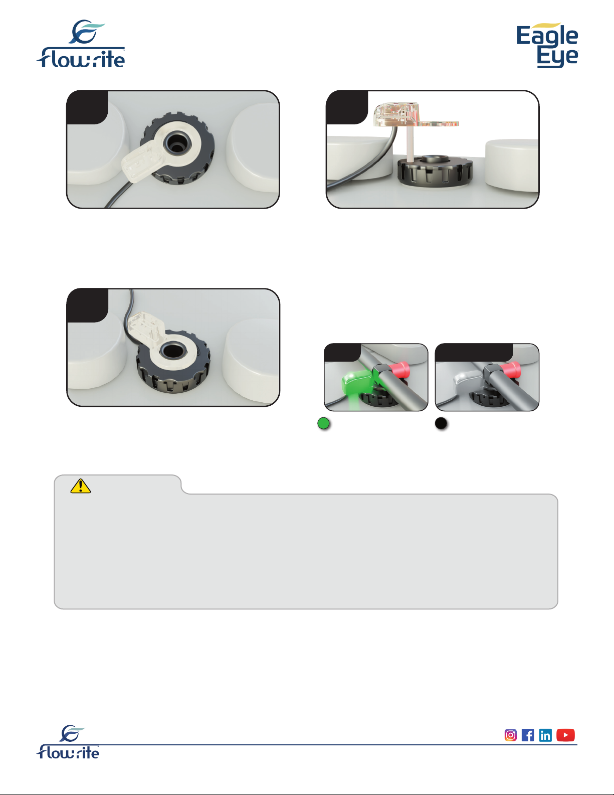
Follow these instructions if there is
interference with cell connector or
other obstacle during installation of
Eagle Eye sensor.
Eagle Eye probe can then be lowered
into the fully seated position.
Install the swivel T.
Lift probe as shown to allow valve to
be rotated into position.
(CAUTION: do not lift probe completely
out of valve. Doing so may damage
sheathing during re-install.)
*3A
3C
3B
Steady green light
indicates full water level.
When light is off, it is time
to water the batteries.
FULL
Follow these instructions (for step 3) for installation on small plate
batteries. All other steps are the same.
NEEDS WATER


