Dinex DiNLOG User manual

DiNLOG®
Emission Monitoring System (EMS)
User’s Manual
Dinex.net

DinLOG – User Manual
DOCUMENT REVISION HISTORY
Revision No.
Revision Date
Revision Description
1.0
05 April 2020
Original document
1.1
24 July 2021
Revision 1.1
1.2
15 February 2021
Telematics module added, modular cable harness
1.3
10 September 2021
Revision 1.3
1.4
25 October 2021
Error 55 added
1.5
01 February 2022
Revision 1.5
1.6
07 March 2022
Standard system document update

DinLOG –User Manual
Page | 3 Rev 1.6
Table of Contents
DOCUMENT REVISION HISTORY..............................................................................................................2
1. GENERAL.............................................................................................................................................4
1.1. System description........................................................................................................................4
2. INSTALLATION.....................................................................................................................................5
2.1. Unpacking the box ........................................................................................................................5
2.2. System components......................................................................................................................6
2.3. Schematic overview ......................................................................................................................9
2.4. Installation instructions................................................................................................................10
2.4.1. LogBase 04 installation.......................................................................................................10
2.4.2. OnRoad Panelbox...............................................................................................................11
2.4.3. Pressure sensor..................................................................................................................11
2.4.4. Temperature sensor............................................................................................................12
2.4.5. Cable harness.....................................................................................................................12
2.5. Initial setup..................................................................................................................................13
3. OPERATING THE SYSTEM...............................................................................................................14
3.1. OnRoad Panelbox.......................................................................................................................14
3.1.1. Buttons ................................................................................................................................14
3.1.2. Operating modes.................................................................................................................14
3.1.3. Logger configuration (maintenance mode) .........................................................................15
4. ALARM CODES..................................................................................................................................19
5. MAINTENANCE..................................................................................................................................20
5.1. Temperature sensor maintenance..............................................................................................20
5.2. Pressure sensor connection kit maintenance .............................................................................20
6. TROUBLESHOOTING........................................................................................................................21
6.1. Symptoms and solutions.............................................................................................................21
7. TECHNICAL SPECIFICATIONS.........................................................................................................22
7.1. DiNLOG LogBase 04..................................................................................................................22
7.2. OnRoad Panelbox ......................................................................................................................23
7.3. Temperature sensor probe..........................................................................................................24
7.4. Pressure sensor..........................................................................................................................25
7.5. Cable harness.............................................................................................................................26
DinLOG – User Manual
Page | 4 Rev 1.6
1. GENERAL
1.1. System description
DiNLOG is a complete, standalone solution for monitoring the status of the diesel particles and diesel
particulate filter. Its function is achieved through continuous measurement, display and logging of
exhaust gas temperature, back pressure, engine speed (rpm) and NOx /O2(optionally).
The values received from the sensors are evaluated and compared with preconfigured settings to
determine whether user intervention or maintenance is needed. For example, if the back pressure values
become too high (indicating that the filter is clogged) or too low (indicating that the filter is damaged), the
system will both alert the user with a visual and audible alarm and save the event in the logger memory.
Alarms generated by an event, together with the visual indications, remain active until the source (e.g.,
measured value) returns to normal levels. Audible notifications are switched off after the alarm is
acknowledged by the user.
The driver can observe the system operation by checking if the exhaust system temperature is within
optimal values for filter operation. If a back-pressure alarm is generated, the driver can raise the
temperature of the exhaust gases by increasing the engine speed and therefore can initiate the system
cleaning. When the back pressure is within the normal values again, visual warning will be turned off.
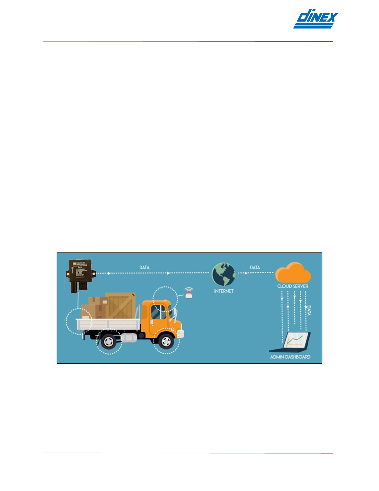
Additionally, the monitoring system can be connected to the PC software for online data monitoring, data
examination or system programming.
Figure 1.1. System overview

DinLOG – User Manual
Page | 5 Rev 1.6
2. INSTALLATION
2.1. Unpacking the box
In the DiNLOG EMS box you can find:
Nr.
Component name
Quantity
1
DiNLOG LogBase 04
1 pc
2
OnRoad Panelbox
1 pc
3
Pressure sensor connection kit (optional)
1 set
4
Temperature sensor connection kit
1 set
5
Cable harness
1 set
6
Battery connection fuse kit
1 set
7
DiNLOG Terminal connection interface (optional)
1 pc
Table 2.1. The components contained inside the box
Temperature sensor probe is included with the Cable harness!
DinLOG – User Manual
Page | 6 Rev 1.6
2.2. System components
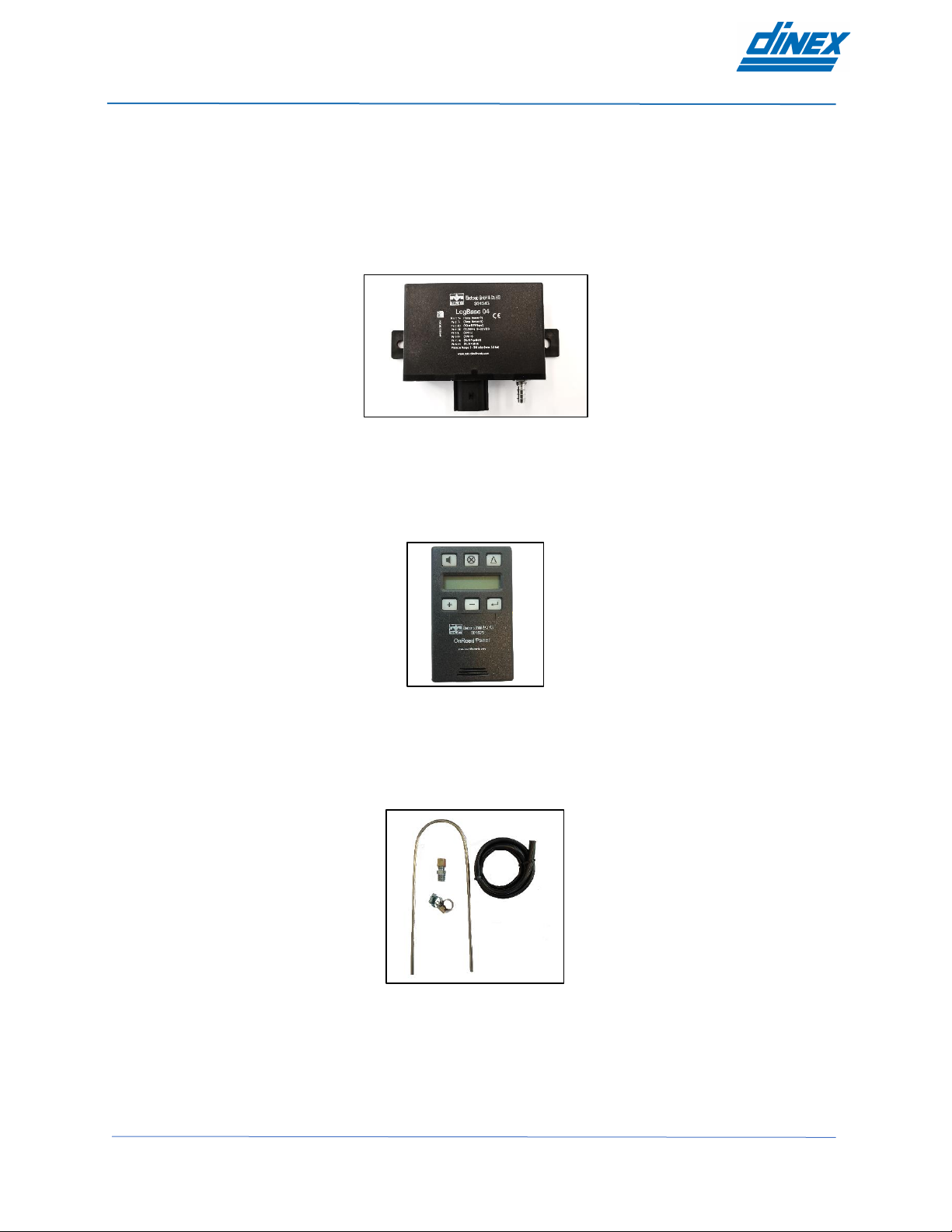
Main component of the DiNLOG EMS system is logger device which is the system brain and monitors all
the other components.
LogBase 04 has integrated pressure sensor, inputs for the temperature sensor probe and single I/O pin
which can be used as frequency input (engine speed/rpm) or alarm output. It also has a CAN bus
interface which is used to connect NOx sensor and OnRoad Panelbox or DiNLOG Terminal software.
Figure 2.1. DiNLOG-LogBase 04
OnRoad Panelbox is the user’s communication interface that is used to communicate with the logger unit.
Panelbox displays the online data, alarms the user, shows the system errors, and can be used to
parametrize the system. It has 6 function keys and buzzer / light notification.
Figure 2.2. OnRoad Panelbox
Pressure sensor connection kit (optional) has all the necessary components to connect the pressure
sensor with a filter. It is consisted of a stainless-steel pipe, ¼ NPT fitting, high temperature hose and
moisture separator (optional).
Figure 2.3. Pressure sensor connection kit
Temperature sensor connection kit has all the necessary components to connect the temperature sensor
with a filter. It is consisted of a ¼ NPT fitting and the temperature sensor itself is a part of the pre-connected
cable harness.
DinLOG – User Manual
Page | 7 Rev 1.6
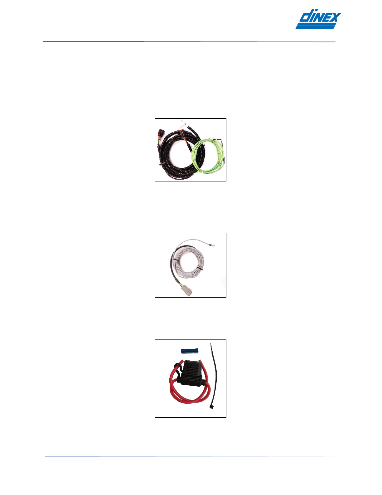
Cable harness is a complete connection kit (wired and tested) that simplifies the system installation. Cable
harness itself is modular which means it’s consisted of separate smaller cable harnesses for each system
component.
Power supply cable harness is used to connect LogBase 04 device to the EMS. Power supply
and I/O are to be connected to corresponding outputs / supplies. Temperature sensor comes pre-attached.
Harness can be further extended via black Deutsch connector.
Black Deutsch connector is used to connect OnRoad Panelbox, NOx sensor or ConnectedLogger module.
Figure 2.4. Power supply cable harness
OnRoad Panelbox cable harness is used to connect the OnRoad Panelbox to the EMS. Gray
Deutsch connector connects directly to Power supply cable harness. Other cable end is connected via RJ45
connector.
Figure 2.5. OnRoad Panelbox cable harness
Battery connection fuse kit has all the necessary components to connect the system to the battery and
acts as an overcurrent protection.
Figure 2.6. Battery connection fuse kit

DinLOG – User Manual
Page | 8 Rev 1.6
DiNLOG Terminal connection interface (optional) is used to connect the system to the DiNLOG
Terminal software running on a Windows PC. This adapter has RJ 45 connector from one side and DB9
connector on the other side. It is necessary to have a PCAN-USB adapter for this purpose.
Figure 2.7. DiNLOG Terminal connection interface
DinLOG – User Manual
Page | 9 Rev 1.6
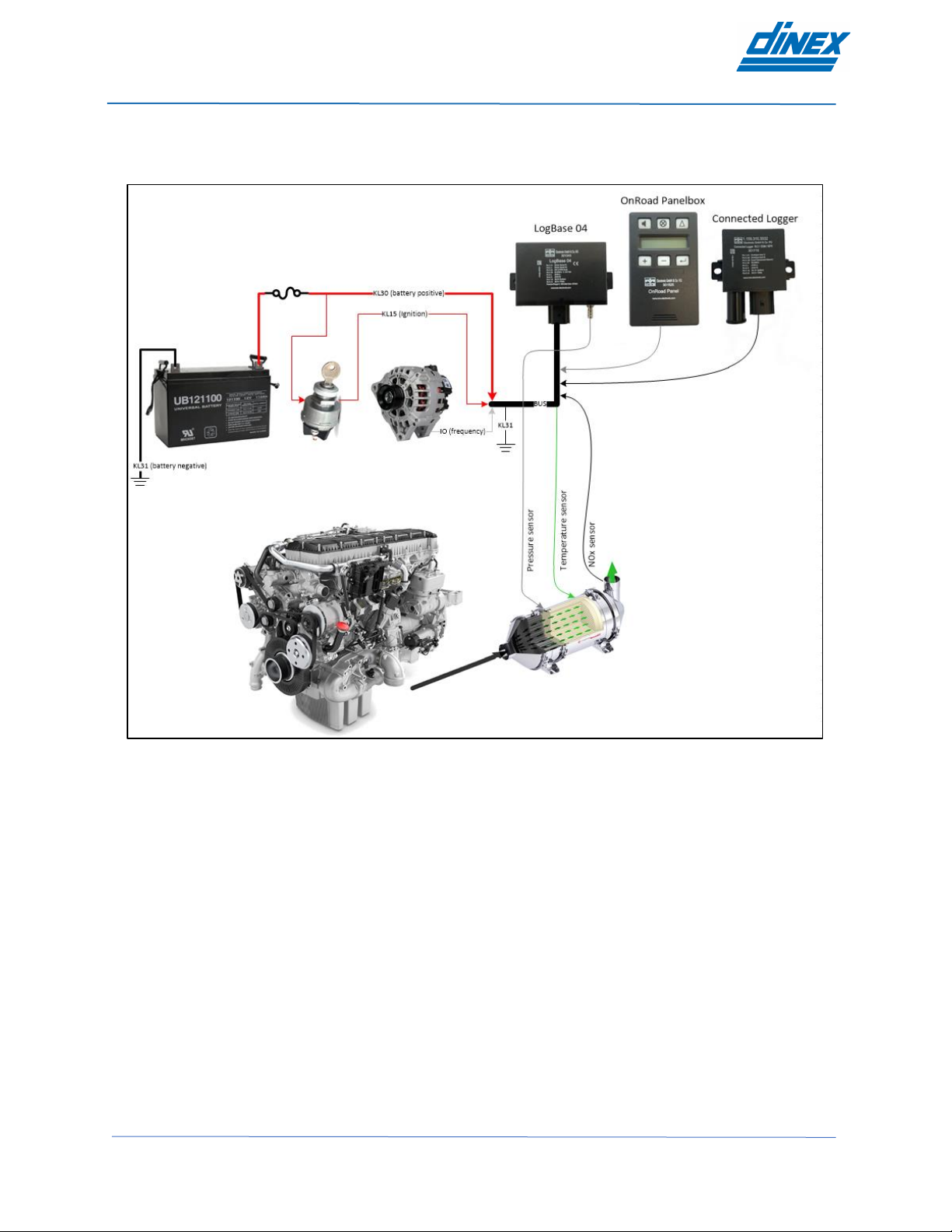
2.3. Schematic overview
A schematic overview of the DiNLOG EMS system and its components is given in the figure below:
Figure 2.8. Schematic overview of the system installation
DinLOG – User Manual
Page | 10 Rev 1.6
2.4. Installation instructions
IMPORTANT: DISCONNECT THE BATTERY PRIOR TO THE INSTALLATION!
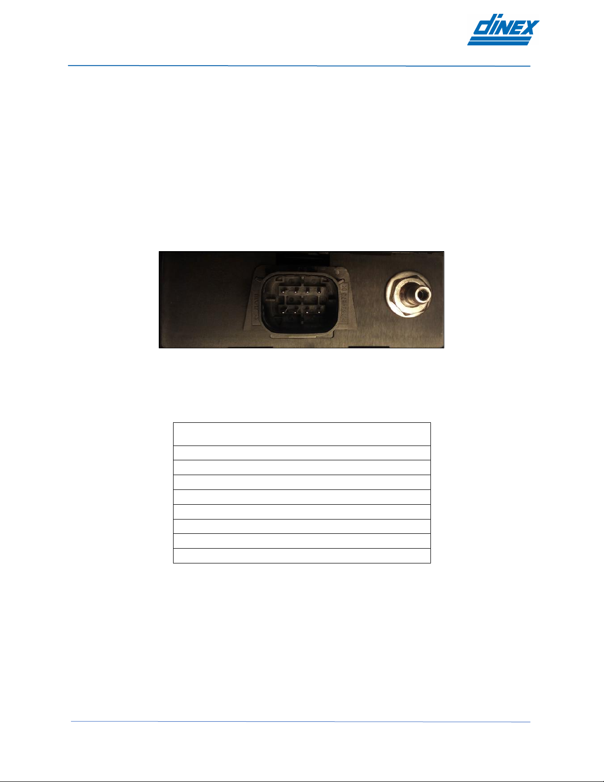
2.4.1. LogBase 04 installation
The LogBase 04 is to be vertically mounted (i.e., its connector positioned downwards), securely fixed and
installed in a position protected against water, excessive heat, and mechanical shock.
The device has two mounting holes, one on each side, with the pressure connection and device connector
being located next to each other.
The connector plug on the logger connects to the cable harness and has a security lock to prevent unwanted
disconnection. To remove the connector from the plug, press the black locking tab firmly and pull connector
from the plug.
Figure 2.9. LogBase 04 front panel connections
2.4.1.1. Pinout
LogBase 04 pinout is listed below:
Pin
number
Pin description
Wire color
1
Temperature sensor P
(green)
2
Temperature sensor N
(white)
3
Input / Output or RPM
(white / black)
4
KL30 / B+
(red)
5
CAN L
(green)
6
CAN H
(white)
7
KL15 / Ignition switch
(red / black)
8
KL31 / Ground
(black)
Table 2.2. LogBase 04 pinout
Table of contents


