Flow 94K HYPERPRESSURE User manual

94K HYPERPRESSURE™
INTENSIFIER
M-376 | REV. G | JUNE 2012

Due to continuing product improvement, the information contained in this document is subject to change without
notice. Flow International Corporation shall not be held liable for technical or editorial omissions made herein, nor
for any incidental or consequential damage resulting from the use of this material.
This document contains information protected by copyright. No part of this document shall be reproduced in any
manner without prior written consent from Flow International Corporation.
© Copyright 1997–2012 Flow International Corporation. All rights reserved.
HyperPressure™ is a trademark of Flow International Corporation.
This document is the original, non-translated version
2 | M-376 © Flow International Corporation
94K HYPERPRESSURE INTENSIFIER

94K HyperPressure™ Intensifier
Chapter 1. Intensifier Description
Physical specifications 5
Functional specifications 6
Operating principles 6
Chapter 2. Safety
Safety precautions 7
Warnings, cautions, and notes 7
Safety tips 8
Protective clothing 9
Emergency medical information 10
Chapter 3. Maintenance Procedures
Periodic maintenance 11
Maintenance tips 11
Maintenance precautions 11
Replacement parts diagram & table 12-14
Intensifier service notes 15
Torque specifications 15
Maintenance Procedure A
Using the Pressure Loading Tool to Assemble &
Disassemble the Intensifier 17
Tools required 17
The pressure loading tool 17
Assembling the intensifier 19
Disassembling the intensifier 21
Maintenance Procedure B
Replacing the Intensifier High-Pressure Seal 23
Service notes 23
Tools required 23
Maintenance Procedure C
Replacing the Intensifier High-Pressure
Cylinder 27
Service notes 27
Tools required 27
Maintenance Procedure D
Replacing the Check Valve Body Assembly and
Servicing the Inlet Components of the Check Valve
Body Assembly 31
Service notes 31
Lapping notes 32
Maintenance Procedure D1
Replacing the entire check valve body assembly 33
Service notes 33
Tools required 33
Maintenance Procedure D2
Lapping the check valve body face and installing
the inlet replacement kit 37
Service notes 37
Tools required 37
Maintenance Procedure E
Servicing and Replacing the Outlet Check Valve
Components 43
Tools required 44
Maintenance Procedure F
Servicing the Low-Pressure Components 47
Tools required 47
Chapter 4. Troubleshooting
Leakage from weep holes 63
Corrective actions 63
Other possible malfunctions 63
Leakage identification charts 64–74
Other possible problems/symptoms for
the intensifier 76
Chapter 5. Parts Lists
Intensifier assemblies 77
Check valve assembly 78
Low-pressure end 79
Piston assembly 81
Kits 82
© Flow International Corporation M-376 | 3
Introduction

Notes
4 | M-376 © Flow International Corporation
94K HYPERPRESSURE INTENSIFIER

CHAPTER 1
Intensifier Description
This manual will help you become familiar with your new Flow International (Flow) equipment. Information was
compiled from the most current information available at the time of publication.
Physical specifications
014623-1 or -3 Long-block intensifier
(Pressure Vessel Application)
Width ..............11.5x12in.(292x304mm)
Length.....................40.5in.(1028.7 mm)
Weight
Intensifier .....................265lb(120kg)
Manifold ........................51lb(23kg)
020070-1 Short-block intensifier (HyperPressure)
Width..................9x6in.(229x152mm)
Length........................42in.(1067 mm)
Weight
Intensifier .....................272lb(124kg)
© Flow International Corporation M-376 | 5

Functional specifications
Typeofshift..........................electric
Outputpressure........... 94,000psi(6483 bar)
Intensificationratio.....................31.4:1
Operating principles
The intensifier pump consists of a hydraulic system, a
high-pressure water delivery system, and a control
system. Details of the control, hydraulic oil and high-
pressure water systems can be found in the intensifier
pump manual.
The water is pressurized by using the fluid pressure in-
tensification principle. Hydraulic oil pressure acting on
the piston results in a force on the plunger, which pres-
surizes the water in the small chamber. Force equilib-
rium is achieved when the water pressure equals the
hydraulic oil pressure times the effective area of the pis-
ton divided by the area of the plunger, assuming no fric-
tion losses. The ratio of the effective piston area to
plunger area is defined as the pressure intensification
ratio.
6 | M-376 © Flow International Corporation
94K HYPERPRESSURE INTENSIFIER

CHAPTER 2
Safety
This chapter contains a comprehensive list of safety pre-
cautions that must be followed to ensure safe operation
of the equipment. These precautions must be read and
understood by everyone operating and maintaining the
equipment—before they start working with the equip-
ment. Note that OSHA and state safety agency rules
must be complied with in addition to those given in this
chapter and elsewhere in this manual. Applicable plant
general safety precautions must also be followed.
Safety precautions
Flow designed your high-pressure waterjet cutting
system and related equipment with safety in mind.
Throughout the manual, safety precautions and warnings
for specific operations are highlighted. Safety precau-
tions are also posted on the equipment. The operator
and service personnel shall pay particular attention to
these precautions at all times.
Operators of a high-pressure waterjet cutting system
must treat the system as they would treat any high-
speed cutting tool. Although the waterjet may appear
harmless, it is a high-energy cutting tool capable of cut-
ting many non-metallic materials such as composites,
plastics, and wood products. Misuse of this equipment
or carelessness in its application can be extremely haz-
ardous to operating personnel. Always treat the waterjet
cutting system with respect.
Warnings, cautions, and notes
Service procedures in the waterjet manuals include
safety warnings, cautions, and notes that must be read,
understood, and adhered to. These are specific catego-
ries of safety notices, and are defined as follows:
WARNING
Highlights an operating condition or service
procedure that can result in death or
serious injury to personnel.
CAUTION
Highlights an operating condition or service
procedure that can lead to impaired system
operation or equipment damage.
Note: Highlights an operating condition or service pro-
cedure that is considered essential for efficient operation
and service.
Replacement labels
•Part # 006317-1
3.75 x 6 in.
•Part # 009837-1
1.8 x 3 in.
© Flow International Corporation M-376 | 7

Safety tips
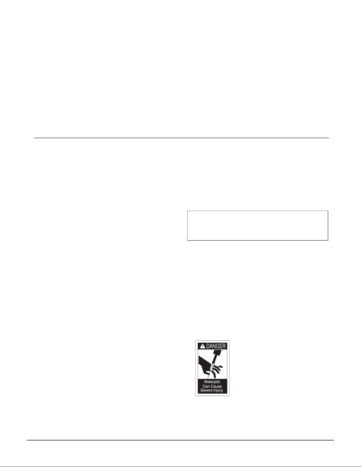
•Do not allow the waterjet stream to touch any part of
your body—it will cause serious injury.
•Do not point the waterjet at anyone.
•During equipment maintenance, take the system out
of service. The controls must be properly locked and
marked with a warning sign.
•All personnel required to perform any system operat-
ing or service function must pay particular attention
to all warning signs and notices posted in the plant
and on the equipment.
•All protective guards, shields, and covers must be in
place on the equipment at all times.
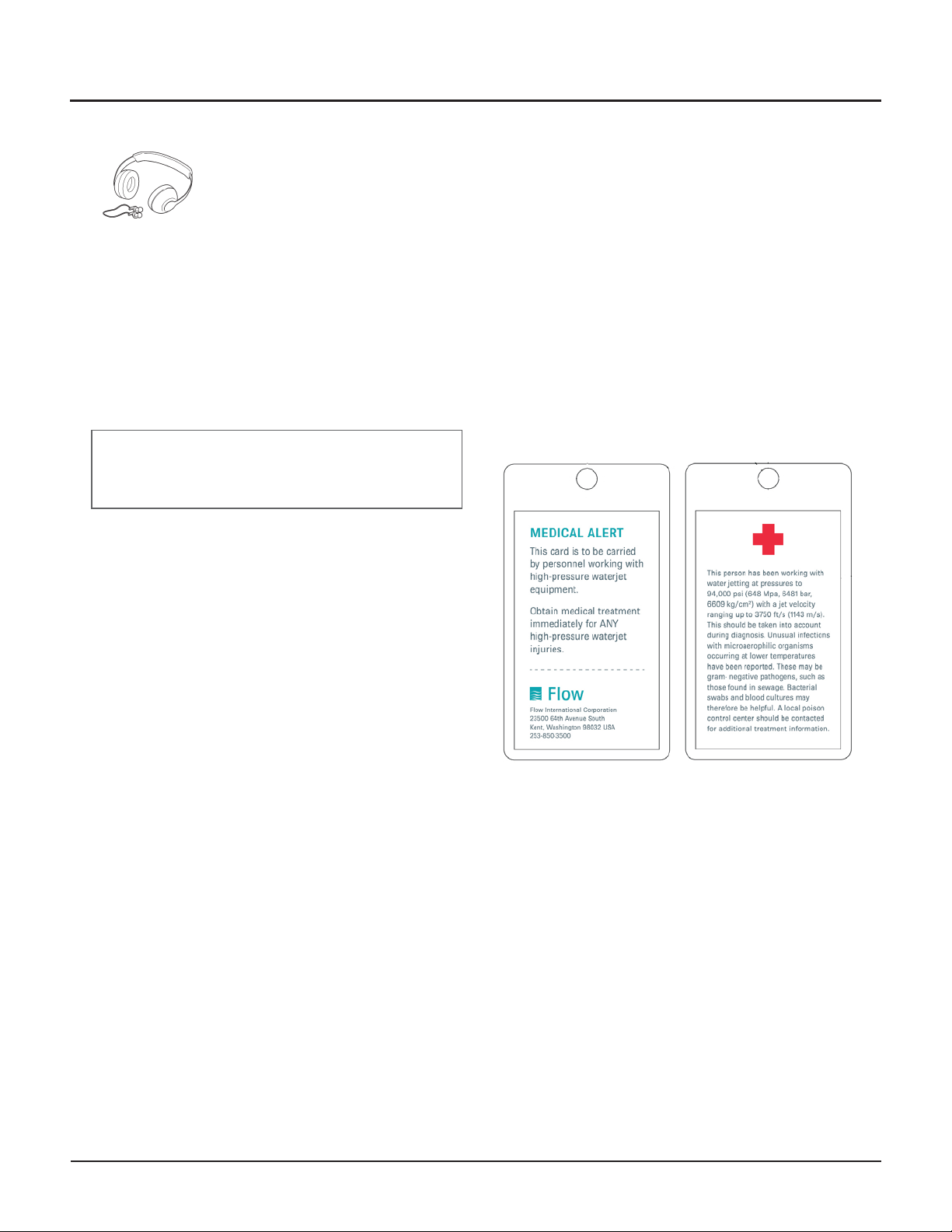
•First aid facilities must be provided in convenient lo-
cations throughout the plant. These locations must
be known by all personnel.
•Always keep the work area around the equipment
clean and free of debris. Oil spillage results in slip-
pery floors and must be cleaned up immediately.
•Any unfavorable conditions that may result in injuries
must be reported to the plant supervisor without
delay.
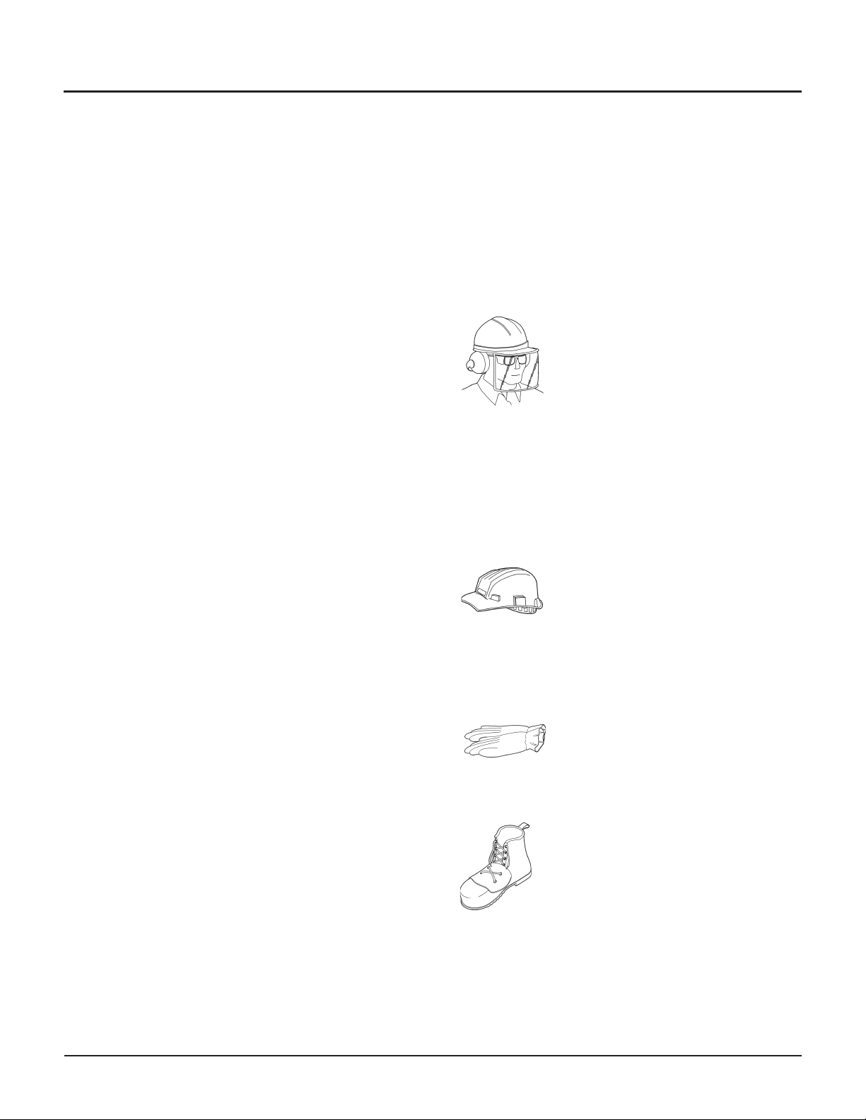
•As a general practice, it is recommended that safety
shoes, glasses, and hearing protection be worn by all
personnel working around the equipment. Do not
wear rings, watches, or necklaces when working
around any equipment that has moving parts.
Mechanical system
•Don’t start the system unless you know how to stop
it.
•Never maintain, service, or clean around the equip-
ment while it is operating.
•Use only the correct tools—wrong tools can cause in-
jury or costly damage to equipment.
•Never climb on or around the equipment on make-
shift devices. Use only approved catwalks, ladders, or
platforms.
•Do not exceed specified pressure setting limits for
pneumatic or hydraulic components. Exceeding
these limits may result in serious injury to personnel
or damage to the equipment.
•Shield and bundle equipment hoses and cables so
they do not obstruct the operator’s freedom of
movement.
•Be alert at all times when working around the
equipment.
•Clear all tools, parts, and rags from moving parts
after servicing the equipment.
Electrical system
•Only properly trained personnel shall perform elec-
trical and/or electronic troubleshooting and servicing
of electrical devices.
•Always assume that power is ON in all electrical
systems. Always check and lock out the main power
switches before servicing the equipment. Post a sign,
"Maintenance in Progress —Do Not Energize."
•Be aware that live electrical circuits are present in the
control console whenever the master disconnect is
on, regardless of whether the E-Stop is engaged.
•Disconnect circuit breakers and lock them in the
OFF position before servicing the electrical system.
If this isn’t possible, have someone stand by to pre-
vent someone from powering up the system.
•Take extra precautions when servicing the power sys-
tem in a damp environment.
•Never alter or bypass protective interlocks or devices
unless specifically instructed to do so, and only if all
precautions are followed.
•You must give capacitors sufficient time for discharge.
If this is not possible, discharging should be done
manually and with care.
•Do not use jumper wires across fuses, fuse holders,
or breakers.
•Make sure all tools are properly insulated for the job.
•Use only proper test apparatus; check regularly to
make sure it is working correctly.
•Use caution when connecting a test probe to test
points.
•All replacement wires must conform to the manufac-
turer’s specifications, including color coding, wire
numbers, and size.
•Close the control panel doors or junction box covers
after servicing.
8 | M-376 © Flow International Corporation
94K HYPERPRESSURE INTENSIFIER

Waterjet system
•High-pressure water can remain in the system for an
extended time after shutting down the water source.
Always bleed-down system pressure before servicing
any part of the system.
•Do not touch weep holes with your bare hands or try
to stop water by plugging the holes.
•Remember that the waterjet stream is a knife. Do not
introduce anything into its path that you do not in-
tend to cut.
•Wear a face shield when required by operating
instructions.
•Do not remove protective shields from high-pressure
tubing. If shields are removed for servicing, they
must be replaced before starting the system.
•Torque all fittings to the manufacturer’s torque
specifications.
•Stepping or leaning on high-pressure tubing can
break connections, causing leakage.
•Use only high-pressure fittings, valves, and tubing
certified for 94,000 psi (6483 bar) when making
alterations or additions to the high-pressure water
system.
•Do not alter or eliminate stress relief tubing coils.
•Follow the tubing manufacturer’s recommendations
for high-pressure tube bending radii.
•Do not exceed specified operating pressures for
high-pressure water system components.
•Do not over-torque fittings or bend swivels
excessively.
•Follow the manufacturer’s recommendations for
servicing the equipment, and use only original
manufacturer replacement parts.
•Follow the manufacturer’s system startup procedure
to ensure safe operation.
•Use care when lifting equipment covers during
operation.
Protective clothing
Personnel operating hand-held, high-pressure water cut-
ting or cleaning equipment and those working nearby
should wear the protective clothing and safety devices
described in this chapter.
Flow recommends that work-site safety personnel ap-
prove all safety equipment and clothing for everyone
working around waterjet equipment.
Eye protection
•At a minimum, operators must
wear safety glasses with side shields
and a visor (or goggles and a visor)
to guard against spray and flying
debris.
•All eye protection shall meet appro-
priate ANSI requirements for that
type of eye protection.
•Some states and countries have
their own eye protection rules that
must be followed.
Head protection
•Helmets must be worn at all times
by all personnel within the work
area.
•Helmet material must withstand
mechanical shock to 10 G in 8 ms
without fracturing.
Hand protection
•The operator must wear gloves at all
times. Leather gloves are preferred.
Foot protection
•Safety footwear with steel toe-caps
0.02 in. (5 mm) thick (minimum)
must be worn. The toe cap must
cover at least 30% of the footwear
length.
•For some applications, footwear
must be equipped with metatarsal
guards to provide instep protection.
© Flow International Corporation M-376 | 9
CHAPTER 2
Safety

Hearing protection
•Operators and other personnel ex-
posed to noise levels of more than
90 dBa for more than 1 hour must
wear suitable ear protection. Ear
plugs and muffs are usually
adequate.
Body protection
•Waterproof garments only protect the operator from
spray and flying debris. They DO NOT provide any
protection from direct jet impact.
WARNING
NEVER point a waterjet cutting or cleaning tool
at yourself or at any person. Do not aim any
waterjet tool at anything you do not want to cut.
Emergency medical information
Anyone who receives equipment-related injuries while
operating high-pressure water equipment should be
given immediate hospital attention. Because it is vital
that medical personnel have information about this type
of injury, all waterjet operating personnel should carry a
waterproof emergency medical tag such as the one illus-
trated below. This card describes the work and the na-
ture of injuries inherent in using waterjet cutting
devices. The card illustrated below can be purchased
from Flow (P/N A-8466).
The tag or card should contain the following standard
information:
10 | M-376 © Flow International Corporation
94K HYPERPRESSURE INTENSIFIER

CHAPTER 3
Maintenance Procedures
Periodic maintenance
Daily inspections and periodic maintenance will help
you get the maximum life, safety, and efficiency from
your Flow equipment. Periodic maintenance is regularly
scheduled preventive maintenance and includes replac-
ing worn parts that have reached the end of their ser-
vice life. It will help minimize unscheduled down time,
maximize equipment use, and eliminate unsafe operat-
ing conditions.
Flow recommends that you use a maintenance and ser-
vice log to record all service work.
Maintenance tips
•Stock enough spare parts to minimize down time
and help avoid rush part orders.
•Practice good housekeeping.
•Assign a complete set of service tools to the work
station.
Maintenance precautions
•Protect all machined and lapped mating surfaces
from damage.
•Carefully clean and blow out all parts being
reassembled. Do not use paper towels.
•Large components such as end bells, end caps,
low-pressure cylinders, and tie rods should be
washed in solvent and dried prior to reassembly.
•Do not use any substitutes for the fluids, sealants,
and lubricants recommended by Flow.
© Flow International Corporation M-376 | 11

Replacement parts
The view of the intensifier shown on Page 16 identifies components that need regular replacement. Maintenance
schedules for these components are identified by item number and description in the following table.
Item Part/component Qty*
Maintenance Replacement
Hours Procedure Parts/kits
Needed Hours Procedure Parts/kits needed
for each intensifier
1*
High-pressure
cylinder
020592-1
2 – – – AR A,C 02592-1
2 per intensifier
2*
Seal carrier
cartridge
052190-1 or
040015-1
2 – – – AR A,B 052190-1 or 040015-1
2 per intensifier
3**
Low-pressure
piston
011304-1 or
020080-1
1 – – – AR A,F
Low-pressure piston
011304-1
Low-pressure seal kit
013157-1 or 020080-1
4
Low-pressure
seal kit
013157-1
1 – – – AR A,F Low-pressure seal kit
013157-1
5*
High-pressure
plunger assembly
010253-1
2 – – – AR A,F
High-pressure plunger
assembly 010253-1
Low-pressure seal kit
013157-1
6* Retaining screw
004380-1 2 – – – AR A, D2
Check valve inlet
replacement kit
014884-1
7*
Inlet check valve
support
010564-1
2 – – – AR A, D2
8* Inlet poppet
015384-1 2– – –AR A, D2
Table references
* Flow recommends changing components on both sides of the intensifier at the same time.
**Use low-pressure piston 011304-1 on the long-block intensifier (052919-10); use low-pressure piston 020080-1 on the
short-block intensifier (020070).
AR = as required
12 | M-376 © Flow International Corporation
94K HYPERPRESSURE INTENSIFIER
no graphic

Replacement parts (continued)
Item Part/Component Qty
Maintenance Replacement
Hours Procedure Parts/Kits
Needed Hours Procedure Parts/Kits Needed
9* Check valve body
020077-1 2AR A,D2
B-1813-3 AR – –
10* O-ring
A-0275-131 2– – – AR – –
11* Check valve seat
014388-1 2– – –
AR A, E
Check valve outlet
replacement kit
014885-1
12* Outlet poppet
011309-1 2– – –
13*
Compression
spring
A-1606
2– – –
14* Outlet spring seat
042102-1 2– – – AR – –
15* Outlet adapter
042101-1 2– – – AR – –
16*
Check valve
assembly
020071-1
2 – – – AR –
Note: Items 9–15 are the components parts of Item 16, Check valve assembly
© Flow International Corporation M-376 | 13
CHAPTER 3
Maintenance Procedures

Replacement parts
14 | M-376 © Flow International Corporation
94K HYPERPRESSURE INTENSIFIER

Intensifier service notes
The following list was compiled from Flow customers
and Field Service Engineers. Following these suggestions
could help lower repair costs, shorten repair time, and
increase service life.
•Everyone working with the equipment must read and
understand all applicable maintenance/service proce-
dures before starting any work on the intensifier
pump, then carefully follow the instructions as they
work through each procedure.
•Carefully check the amount of water seepage from
the end bell weep hole. If leakage is less than 2 tea-
spoons (0.8 oz/23ml) per stroke and has not sud-
denly appeared or drastically increased, you do not
need to immediately stop the pump and change
seals. However, you should schedule maintenance as
soon as possible.
•Seals should be replaced when you are not able to
maintain correct pressure.
•Except for a complete overhaul or repairs that in-
volve the hydraulic oil cylinder, it is usually easier
and quicker to do repair work on the intensifier
while the intensifier remains on the pump frame.
However, this is not recommended in environments
where there is excessive dust or contamination.
•Repair all cracked parts and leakage from the check
valve immediately.
•Clean all parts with a clean, non-residue type solvent
such as Citra-safe or isopropyl alcohol. Use a dedi-
cated solvent tank if possible.
•All threaded high-pressure connections require a
fresh, even coating of Blue Lubricant. Clean parts
thoroughly, then apply new lube. Do not substitute
another product.
•All parts that contain high-pressure water (cylinder,
check valve body, tubing) are susceptible to stress fa-
tigue accelerated by stress risers. Stress risers result
when scratches, nicks, or other surface disruptions
are present. Do not attempt to rework damage. You
must replace the component.
•High-pressure seal life and the service life of several
other parts is related to the stress put on the parts—a
function of stroke rate and water pressure. Exceeding
the pump rating can lead to increased cost and
downtime.
•Keep all intensifier tools supplied with the pump in a
separate, locked cabinet. Substituting tools for those
supplied by or available from Flow is not
recommended.
•Use the intensifier assembly fixture when reassem-
bling the low-pressure cylinder. Problems with the
manifold and leaking o-rings are significantly reduced
when the fixture is used.
•Keep the work area clean. When reassembling any
intensifier, clean hands, shop coat, rags, parts, tools,
air, solvent and lubricants all contribute to lower
maintenance costs and reduced down time.
Torque specifications
Refer to the following table when specific torque re-
quirements are not listed in a service procedure.
Mounting bolts and machine screws shall not be
torqued beyond the manufacturer’s recommended
limits.
High-pressure gland nuts U.S.
ft-lb
SI
N-m
1
4-in. 15-25 20-34
38-in. 35-45 47-60
916-in. 60-75 80-100
Note: Lubricate threads for all high-pressure tubing connec-
tions with Blue Lubricant before assembly.
© Flow International Corporation M-376 | 15
CHAPTER 3
Maintenance Procedures

Notes
16 | M-376 © Flow International Corporation
94K HYPERPRESSURE INTENSIFIER

Maintenance Procedure A
Using the Pressure Loading Tool to Assemble and
Disassemble the Intensifier
Tools required
Pressure loading tool kit (042512-3)
½in.drivetorquewrench
½in.driveratchet
158in. crow’s foot wrench (½ in. drive)
158in. socket (½ in. drive)
1½ in. socket (½ in. drive)
1 in. open-end wrench
78in. open-end wrench
13 16 in. open-end wrench
Food grade grease (A-4689)
Blue Lubricant (A-2185)
Anti-seize (A-10039)
The pressure loading tool
The following procedures use a special tool created especially for the
94K HyperPressure intensifier. You must read and understand these
usage notes before attempting any maintenance procedure that re-
quires the use of this tool. Failure to do so could damage the tool
and/or the component being serviced. Such damage is not covered
by warranty.
© Flow International Corporation M-376 | 17

Usage and service notes
•The pressure loading tool is a delicate instrument and
must be handled with care.
•Use only approved hydraulic oil in the hand pump.
•It is critical that service technicians be trained in the
assembly and disassembly procedures of the intensi-
fier before they use the pressure loading tool.
•Do not use the pressure loading tool for anything
other than the assembly and disassembly of the
intensifier.
•It is important to collapse the tool (push the piston
fully into its cylinder) before each use as described in
this section, to prevent accidental separation of the
tool.
•Inspect the tool piston stop for damage. Replace if it
is not flat. DO NOT grind to remove damage.
•For ease of use and to prevent damage, Flow recom-
mends that you mount the hand pump permanently
to a rigid cart. When not in use, cover the cart with a
dust cover and store in a clean location.
•When storing the pressure hose, do not kink or bend
it.
•Always keep dust caps in place on the quick discon-
nect fittings when the tool is not in use.
•Once a year, the pressure gauge of the tool should
be calibrated by a qualified laboratory.
18 | M-376 © Flow International Corporation
94K HYPERPRESSURE INTENSIFIER

Assembling the intensifier
The illustrations on this page identify the parts used in
this procedure, and provide a visual description of how
the tool assembles to the tie rods of the intensifier.
1. Apply anti-seize (A-10039) to all exposed threads of
each tie rod. Apply anti-seize to the threads of the
end cap nuts and tool nuts and the contacting faces
of the nuts and their washers.
2. With the high-pressure seal assembly, high-pressure
cylinder, filler tube, check valve assembly, and end
cap in place, install the end cap washers and nuts on
the tie rods and run up hand tight to the end cap.
3. Install the tool on the tie rods and locate the tool pis-
ton step in the end cap counterbore.
CAUTION
Make sure the tool piston step is fully engaged in the
counterbore before continuing. Failure to do so can damage
the end cap or the pressure loading tool.
4. Install the tool washers and nuts on the tie rod ends
and run up hand tight to the tool.
© Flow International Corporation M-376 | 19
CHAPTER 3
Maintenance Procedures

5. Connect the hand pump hose to the tool at the
quick-disconnect fitting (see below).
Note: On some tool models the hand pump hose
does not have a quick-disconnect fitting. If this is the
case, leave the hose attached to the tool at all times
to prevent leaking.
6. Open the pressure-release valve on the hand pump
by turning the valve handle counter-clockwise one
turn.
7. Collapse the pressure loading tool using a ratchet
and socket on the tool nuts. In the pattern shown be-
low, torque the tool nuts to 20 ft-lb (27 N-m), then
to 50 ft-lb (67.8 N-m).
Note: Oil from the tool will flow back to the hand
pump reservoir.
8. Close the hand pump pressure-release valve by turn-
ing the valve handle clockwise until tight.
9. Pump the tool to 9200 psi (634 bar).
Wait 10 seconds, then recheck the gauge. If the
needle falls off the mark, re-tighten the pump pres-
sure relief valve and bring the pressure back up to
the 9200 psi (634 bar) mark.
10. Run up the end cap nuts by hand. Using a torque
wrench with a crow’s foot end, torque in the pattern
indicated (see illustration below) to 50 ft-lb
(67.8 N-m).
Note: The pressure reading will drop as the nuts are
torqued. This is normal; do not adjust pressure.
CAUTION
Do NOT repump the tool after starting the
end cap nut torquing. Repumping the tool
can cause misalignment and break parts.
11. Bleed off the remaining tool pressure by opening the
pump pressure-release valve.
12. Remove the hand pump hose from the tool at the
quick-disconnect fitting.
Note: On some tool models the hand pump hose
does not have a quick-disconnect fitting. In this case,
the hose should be left attached to the tool at all
times to prevent leaking.
13. Remove the pressure loading tool nuts and washers.
Remove the tool.
20 | M-376 © Flow International Corporation
94K HYPERPRESSURE INTENSIFIER
Table of contents
Other Flow Water Pump manuals
Popular Water Pump manuals by other brands

DeWalt
DeWalt Graco PowerFill 3.5 Standard 26B417 Operation, parts

BEKA
BEKA ZEPTO Original operating and assembly manual

Alemite
Alemite 9911-A1 Service guide

Pentair Jung Pumpen
Pentair Jung Pumpen PLANCOFIX LINE instruction manual

LUBE
LUBE VBP-1-18LP instruction manual

SUN RUN
SUN RUN SPA-554TQ operating instructions