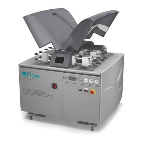
Flow ESL INTENSIFIER User manual

ESL INTENSIFIER
M-310 | REV. G | JANUARY 2009

Due to continuing product improvement, the information contained in this document is subject to change without
notice. Flow International Corporation shall not be held liable for technical or editorial omissions made herein, nor
for any incidental or consequential damage resulting from the use of this material.
This document contains information protected by copyright. No part of this document shall be reproduced in any
manner without prior written consent from Flow International Corporation.
© Copyright 1997–2009 Flow International Corporation. All rights reserved.
2 | M-310 © Flow International Corporation
ESL Intensifier

Contents
Introduction
Introduction 4
Safety 4
Related documents 4
ESL intensifier description
Specifications 5
Operating principles 5
Maintenance & service
Periodic maintenance 6
Maintenance tips 6
Maintenance precautions 6
Torque specifications 6
Troubleshooting 7
Intensifier weep hole identification 7
Using the troubleshooting guide 8
Troubleshooting guide 9
Service procedures 12
Intensifier service notes 12
Major parts of the intensifier 13
High-pressure water cylinder and seals 14
End cap and check valve 20
Lapping the sealing surfaces 24
Hydraulic oil cylinder, piston, plunger,
and end bell 26
Parts
Parts list information 32
Ordering parts 32
Customer Service 32
Technical Service 32
Top assemblies 33
Sub-assemblies 35
Check valve 35
Piston assembly 36
Manifold assembly 37
Kits 39
Check valve kits 39
Tool kits 39
High-pressure seal kits 40
Low-pressure seal kits 41
© Flow International Corporation M-310 | 3
ESL Intensifier

Introduction
This manual will help you become familiar with your new Flow International equipment. Information was compiled
from the most current information available at the time of publication.
Safety
A comprehensive list of safety precautions is located in your pump manual. These precautions must be reviewed
and understood by operating and maintenance personnel before installing, operating or servicing the equipment.
The high-pressure waterjet system is a powerful cutting tool and must always be treated with respect.
Warnings, cautions, and notes
Before operating the equipment, please thoroughly understand and adhere to all warnings, cautions, and notes that
appear in this manual. These are defined as follows:
WARNING
Highlights an operating or service procedure or condition
that can result in death or serious injury to personnel.
CAUTION
Highlights an operating or service procedure or condition that can lead
to impaired system operation or equipment damage.
Note: Highlights an operating or service procedure or condition that is essential for efficient operation and service.
Related documents
Your equipment was shipped with several manuals. Some are shipped with every system; others are specific de-
pending on the model of intensifier pump purchased. Other manuals than those listed may have been shipped
with your system if the ESL intensifier was installed as a retrofit kit.
Every system comes with the following manual:
•M-127, Small High-Pressure Components
One of these pump and/or system manuals was shipped with the equipment:
•M-287, 7X Intensifier Pump
•M-294, 25X Intensifier Pump
•M-331, 20XW Intensifier Pump
•M-368, IFB DWJ 50iS
•M-371, IFB 50iS
•M-378, IFB DWJ 100iD
•M-380, IFB 100iD
•M-373, WMC2 50iS
•M-375, WMC2 100iD
•M-377, 30XQ Pump
•M-384, IFB StoneCrafter
•M-387, 30SA Intensifier Pump
4 | M-310 © Flow International Corporation
ESL Intensifier

ESL intensifier description
The ESL intensifier is available in 60,000 psi (4138 bar)
and 40,000 psi (2759 bar) output water pressure
ratings.
Specifications
Diameter .........................................7 in. (178 mm)
Length ............................................32 in. (809 mm)
Weight ..............................................105 lb (48 kg)
Type of shift..................................................electric
Output pressures.......................60K/20:1, 40K/20:1
Hydraulic oil
kinematic viscosity.............310 SSU @ 100°F (38°C)
Hydraulic oil
Oil must be ISO viscosity grade 46. The following oils
are recommended, but other manufacturer's equiva-
lents can be used.
•Mobil DTE Medium or DTE 25
•Shell Turbo T 46
•Chevron Turbine Oil GST 46
•Texaco Regal R&O 46
Operating principles
The intensifier pump consists of a hydraulic system, a
high-pressure water delivery system, and a control sys-
tem. Details of the control, hydraulic oil,and high-
pressure water systems can be found in the following
manuals:
•Intensifier pump manual or the intensifier pump
chapter of an IFB or WMC system manual
•MS-2275, Ultrahigh-Pressure Pump Operating
Principles
© Flow International Corporation M-310 | 5
ESL Intensifier

Periodic maintenance
Daily inspections and periodic maintenance will help
you get the maximum life, safety, and efficiency from
your FLOW equipment. Periodic maintenance is regu-
larly scheduled preventive maintenance and includes
replacing worn parts that have reached the end of their
service life. It will help minimize unscheduled down
time, maximize equipment use, and eliminate unsafe
operating conditions.
Flow recommends that you use a maintenance and ser-
vice log to record all service work. Maintenance Log
MS-2258 is provided on the CD.
Note: Review all maintenance precautions and safety
instructions listed in the intensifier pump manual.
Maintenance tips
•Stock enough spare parts to minimize downtime
and help avoid rush part orders.
•Practice good housekeeping.
•Assign a complete set of service tools to the
workstation.
Maintenance precautions
•Protect all machined and lapped mating surfaces
from damage.
•Carefully work out any damage to seal surfaces, or
seal damage and leaks will be a recurring problem.
•Carefully clean and blow out all parts being reas-
sembled. Do not use paper towels.
•Do not use any substitutes for the sealants and lu-
bricants recommended by Flow.
Torque specifications
Refer to the following table when specific torque re-
quirements are not listed in a service procedure.
Mounting bolts and machine screws shall not be
torqued beyond the manufacturer’s recommended
limits.
High-pressure
gland nuts
U.S.
(ft-lb)
SI
(N-m)
14in. 15-25 20-34
38in. 35-45 47-60
916 in. 60-75 80-100
Note: Before assembly, lubricate threads of all
high-pressure tubing connections with Blue Lubricant.
6 | M-310 © Flow International Corporation
ESL Intensifier

Troubleshooting
Intensifier weep hole identification
Water leaking from weep holes can provide clues to
the condition of components, depending on the tem-
perature and force of the water.
Included with this manual is an intensifier troubleshoot-
ing illustration that identifies the weep holes described
below.
Check valve outlet body
Leakage can be caused by the following:
•Loose high-pressure connection
•Cracked or scored check valve outlet body
•Scored high-pressure tubing
Repair any problems immediately.
Main check valve body
Leakage can be caused by a loose connection and/or a
cracked or scored main body, insert, or outlet body.
Repair any problems immediately.
End cap
High-pressure water seal seepage is the most common
cause for end cap weep hole leakage. It can be caused
by a loose end cap, failure of the high-pressure seal be-
tween the cylinder and check valve main body, failure
of check valve body o-rings, or a cracked or scored
high-pressure water cylinder or check valve main body.
Cold water leaking from this weep hole can be caused
by a damaged o-ring on the check valve body or a
damaged high-pressure seal, whether or not the inten-
sifier is running.
Check leakage quantity. If seepage is very gradually in-
creasing, has not suddenly appeared, is no more than
lukewarm, and is less than two teaspoons
(0.8 oz/23 ml) per stroke, it is safe to continue to oper-
ate the pump. See Intensifier Service Notes.
End bell
The weep hole is drilled into the void separating the
hydraulic oil cylinder and the high-pressure water cylin-
der. Hydraulic oil leakage can be caused by:
•Failure of the end bell hydraulic oil seal and/or
•Cracked or scored end bell or plunger
Leakage is usually due to end bell oil seal damage.
Normal oil seal leakage can be up to one drip per hour.
Water leakage from the end bell weep hole is usually
caused by failure of the high-pressure water seal lo-
cated in the end of the cylinder, but can also result
from a cracked or scored high-pressure water cylinder
or plunger.
Check leakage quantity. If seepage very gradually
increases, has not suddenly appeared, is no more than
lukewarm, and is less than two teaspoons
(0.8 oz/23 ml) per stroke, it is safe to continue to
operate the pump. See Intensifier Service Notes.
© Flow International Corporation M-310 | 7
ESL Intensifier

Troubleshooting guide
The troubleshooting guide will help you identify the
probable cause of a system malfunction and the most
effective corrective action.
Using the troubleshooting guide
The probable causes of each malfunction are listed in
order from the most likely to the least likely to occur.
The corrective action is a condensed summary of the
service required to remedy the problem. When you
encounter a system malfunction:
1. Carefully and precisely define the problem.
2. On the troubleshooting table, locate the symptom
that most closely resembles your assessment of the
problem.
3. Identify the most likely probable cause.
4. Follow the corrective action procedure.
If the symptoms in the chart do not correspond to your
malfunction, or if the problem is not resolved or elimi-
nated by the recommended corrective action, contact
Flow Technical Service.
8 | M-310 © Flow International Corporation
ESL Intensifier

Troubleshooting guide
1. Intensifier strokes unevenly
Leaky check valve (inlet or outlet) on
one side only
Replace or rework the check valves as necessary. For best results, lap or re-
place all check valves at the same time.
Foreign particles trapped between
check valve and seat
1. Remove the end cap(s). Eliminate the sources of contamination to prevent
problem from recurring.
2. Examine the check valves and remove any foreign material. Relap if neces-
sary.
3. Clean all parts and reassemble.
Worn/bent shift cable or associated
parts (mechanical shift only)
1. Remove the shift cable guide.
2. Install the spare shift cable guide and recheck. Replace any worn parts.
High-pressure water plunger has
separated from the oil piston
Associated with a drop in output water pressure and flow. Avoid prolonged
operation under this condition—it will cause severe damage to the intensifier.
Disassemble the hydraulic oil cylinder and piston and replace parts if defec-
tive.
Wrong shift/actuator pins installed Replace with bronze shift/actuator pins (002226-1 mechanical shift; B-1702-1
electric shift).
Debris in shift circuit Check spool movement on both the pilot and shift valves. Inspect spools for
defects. Hand lap with 600 grit paper. If unable to remove defects, replace
valve.
2. Intensifier knocks severely
Low inlet water pressure to the in-
tensifier
1. Make sure the inlet water pressure output is above the required minimum
for your intensifier pump.
2. Replace filters in filtration system; make sure they are replaced in the same
order they were removed.
Intensifier inlet passages clogged by
debris or corrosion
1. Inspect the filtered water inlet lines.
2. Remove the end cap. Inspect and remove any foreign material clogging the
inlet passages.
3. Inspect the check valve.
Sticky outlet check valve poppet 1. Remove the end cap.
2. Relap the check valve poppet and the insert; reinstall.
3. Oil leakage from end bell weep hole
Worn end bell oil seal Replace the end bell oil seals. Replace all oil seals at the same time.
4. Oil leaking from manifold/end bell interface
Defective/worn o-ring seals, or loose
manifold mounting screws or port
plugs on valve
Retorque the manifold mounting screws, following the torque values provided
in this section. If leak will not stop, replace the o-ring interface seals between
the manifold and the end bells. Lap manifold if the o-ring surface is nicked.
© Flow International Corporation M-310 | 9
ESL Intensifier

Misaligned end bells 1. Remove intensifier from pump and place on assembly fixture.
2. Loosen tie rods and retorque. Confirm that end bells are aligned correctly.
5. Oil leaking from manifold/shift valve interface
Defective or worn o-ring seals; loose
shift valve mounting screws
Retorque the shift valve mounting screws, using torque values in this manual. If
leak doesn't stop, replace interface o-ring seals between manifold and shift
valve.
6. Oil leaking from shift valve/pilot valve interface
Defective/worn o-rings, loose pilot
valve mounting screws, or incorrect
torque
Retorque pilot valve mounting screws, following the torque values in this man-
ual. If leak won’t stop, replace interface o-ring seals between pilot valve and
shift valve.
7. Water leaking from end bell weep hole
Worn high-pressure water seal Replace all high-pressure water seals and seal backup rings. Be careful not to
scratch the water cylinder during seal extraction and insertion.
Fractured high-pressure water cylin-
der at the end bell side
Replace water cylinder and seals. Be careful not to scratch the high-pressure
water cylinder during seal insertion.
Worn high-pressure water plunger 1. Inspect plunger diameter. The diametrical clearance between plunger and
new backup ring must be less than 0.002 inch (0.05 mm). Replace if
scratched, pitted or below tolerance.
2. Replace water seals and seal backup ring.
8. Water leaking from end cap weep hole
Worn HP water seal Replace high-pressure water seal.
Damaged low-pressure water seal
o-rings on the check valve body
Replace water seal o-rings. Do not pinch the o-ring seals when installing check
valve housing.
Fractured high-pressure water cylin-
der
Replace cylinder and high-pressure seals. After replacement, increase pressure
gradually.
Fractured check valve body Inspect for fractures. Replace check valve body if required. Replace all water
seals.
End cap incorrectly assembled to
high-pressure cylinder
Remove end cap and reassemble. Replace HP water seal (if damaged).
9. Short high-pressure water seal life
Excessive clearance between seal
backup ring and HP water plunger
1. Remove HP water cylinder. Replace all HP water seals (backup ring, seal,
hoop, and o-ring).
2. Examine HP plunger. Replace if diameter is less than specified or if surface
roughness is greater than 4 micro-inch RMS.
Caution: High-pressure seal rings must be replaced whenever high-pres-
sure seals are replaced.
Scratched HP water plunger Deep pits or scratches in excess of 10 micro-inches will cause premature
high-pressure water seal failure. Replace as necessary.
10 | M-310 © Flow International Corporation
ESL Intensifier

Excessively worn HP water cylinder Examine for wear, particularly at the ends of the bore. Replace if ID is greater
than specified. Replace if pitted or eroded in seal areas.
Contaminated water Analyze water sample. Inspect water filters.
10. Water leaking from check valve weep hole
Worn or damaged outlet check
valve insert and/or poppet
Loose outer body adapter or outlet
body
Rework or replace outlet check valve insert and poppet. Always torque fittings
to the recommended torque value.
11. Fractured high-pressure water cylinder
Stress fatigue Replace HP water cylinder. The cylinder has a limited fatigue life, and will re-
quire periodic replacement depending on the application. Premature failure is
primarily attributed to scratches in the bore. Replace all water seals whenever
replacing the high-pressure water cylinder. Record service intervals and work
for future reference.
12. Fractured check valve body
Stress fatigue Replace HP water cylinder. The cylinder has a limited fatigue life, and will re-
quire periodic replacement depending on the application. Premature failure is
primarily attributed to scratches caused during assembly or installation. Relap
or replace the check valves if the HP water cylinder is replaced.
© Flow International Corporation M-310 | 11
ESL Intensifier

Service procedures
The service procedures contain step-by-step instruc-
tions and illustrations to explain how to service the
equipment. Service procedures cover how to replace
parts during scheduled or unscheduled maintenance,
and also include preventive maintenance procedures to
help ensure trouble-free operation of the machinery.
Note: Information on high-pressure components (such
as swivels, filters, and tubing) is in manual M-127,
Small High-Pressure Components.
Intensifier service notes
The following list was compiled from Flow customers,
technicians, and operators. It can help to lower repair
costs, shorten repair time, and increase component life.
•Read and understand each procedure before start-
ing any work on the intensifier pump.
•Measure the amount of water seepage from the
end cap and end bell weep hole. If less than 2 tsp
(23 ml) per stroke and has not suddenly appeared
or increased drastically, you do not need to imme-
diately stop the pump and change seals. However
you should schedule maintenance as soon as
possible.
•Except for a complete overhaul or repairs involving
the hydraulic oil cylinder, it is usually easier and
quicker to work on the intensifier while it is in the
cabinet (this is not recommended for dusty envi-
ronments such as paper, fiberglass or plastic
manufacturers).
•Immediately replace all cracked check valve parts
and clean up leakage.
•All threaded high-pressure connections require a
fresh, even coating of Blue Lubricant. Do not sub-
stitute another product.
•Clean all parts with a clean, non-residue solvent
such as Citra-Safe or isopropyl alcohol. Use a dedi-
cated solvent tank if possible. Contamination from
other industrial parts will seriously reduce part life.
•All parts that contain high-pressure water (cylinder,
check valve housing, tubing) are susceptible to
stress fatigue accelerated by stress risers. Stress ris-
ers are caused by scratches, nicks or other surface
disruptions. Rework damage or replace the
component.
•High-pressure water seal life and the service life of
other parts are related to the stress put on the
parts—a function of stroke rate and water pres-
sure. Exceeding the pump ratings can lead to in-
creased cost and downtime.
•Keep all intensifier tools supplied with the pump in
a separate locked cabinet. Substituting tools for
those supplied by or available from Flow is not
recommended.
•Use the intensifier assembly fixture when reassem-
bling the hydraulic oil cylinder. Problems with
manifolds and leaking o-rings are significantly re-
duced when the fixture is used.
•Keep the work area clean. When reassembling any
intensifier, remember that clean hands, shop coat,
rags, parts, tools, air, solvent, and lubricants all
contribute to lower maintenance costs and re-
duced downtime.
12 | M-310 © Flow International Corporation
ESL Intensifier

Major parts of the intensifier
© Flow International Corporation M-310 | 13
ESL Intensifier
Check valve assembly
High-pressure cylinder assembly

High-pressure water cylinder and seals
The intensifier requires no periodic maintenance.
However, when seals leak excessively or if you find a
stress fracture, repair the intensifier immediately. See
Intensifier weep hole identification.
If you are servicing only the high-pressure water cylin-
der and related components, you can leave the intensi-
fier mounted in the pump frame. Keep the work area
clean and free of airborne fiber and dust.
Service steps
WARNING
Place the main electrical disconnect in the OFF
position and bleed down all high-pressure lines.
Place an Out of Service tag on the main electrical
disconnect and lock it out. Failure to do so can
cause equipment damage or injury to personnel.
1. Shut down the system.
2. Disconnect the supply water hose at the quick-
disconnect. Using two wrenches, disconnect the
high-pressure water line from the check valve outlet
body. Loosen the other end and move the tubing
out of the way.
CAUTION
Do not bend or flex the high-pressure
tubing—this can cause it to fail prematurely.
3. Note the orientation of the main check valve body,
then loosen the end cap by tapping the spanner
wrench with a mallet. If necessary, remove the cable
guide, then hold onto the high-pressure water cylin-
der with a strap or girth wrench.
CAUTION
DO NOT grip the cylinder with any sharp-toothed tool.
Surface scratches and gouges will lead to early part failure.
4. Unscrew the end cap from the cylinder by hand;
make sure the check valve assembly and the end
cap turn as an assembly.
CAUTION
If the check valve and end cap do not turn
together, the check valve body o-rings can
be damaged. If necessary, use a wrench.
14 | M-310 © Flow International Corporation
ESL Intensifier

5. Set the end cap aside. Flow recommends that you
service the check valves at every regular seal re-
placement interval, following the procedure in End
Cap and Check Valve.
When the check valve service is complete, continue
with Step 6.
6. Loosen the high-pressure cylinder using a girth or
strap wrench.
CAUTION
DO NOT grip the cylinder with any sharp-toothed tool.
Surface scratches and gouges will lead to early part failure.
7. Remove the cylinder by hand, carefully sliding it off
the plunger to avoid scoring the plunger or the seal
backup sleeve (located inside the cylinder).
8. Use the seal tool to remove the high-pressure seals
from the cylinder. Check the seals for flaws and re-
place as needed.
High-pressure seal tool kit
© Flow International Corporation M-310 | 15
ESL Intensifier
High-pressure cylinder assembly

9. Remove and discard the seal ring. The seal ring is a
wear item and is replaced at every seal change.
10. Clean the plunger and inspect for damage. The
plunger must have a smooth surface with no
scratches, pits, or other damage.
Note: If the plunger is damaged, it must be re-
placed. Wrap the cylinder and end cap in a lint-free
material and set aside. See Hydraulic Oil Cylinder,
Piston, Plunger and End Bell for the replacement
procedure.
When the plunger has been replaced, continue with
Step 11.
11. Clean and inspect all four components of the
high-pressure seal tool kit, especially those surfaces
that will contact the seal, backup sleeve, and cylin-
der. Smooth off any rough edges.
12. Place the high-pressure cylinder on a clean, dry
shop towel. Using a mallet, tap the shouldered end
of the seal installation tool into the end of the cylin-
der to remove the seal located in the opposite end.
Repeat to remove the seal in the other end of the
cylinder.
13. Remove the seal backup sleeve.
14. Carefully clean the high-pressure cylinder and
backup sleeve.
Note: High-pressure components must be cleaned
in a non-residue solvent and allowed to air dry be-
fore reassembly.
15. Inspect all surfaces of the cylinder for damage or fa-
tigue. Inspect the inside surface by looking through
the cylinder angled toward a brightly lit white sur-
face. If there is any damage to the interior, discard
and replace the cylinder.
CAUTION
Do not reassemble any intensifier
that has a damaged cylinder.
16. Inspect the sealing surfaces of the cylinder for rough-
ness or damage. Minor build-up or erosion can be
polished out by hand if done evenly. There must be
no nicks or scratches on any sealing surface.
17. Inspect the seal backup sleeve for any signs of dam-
age. The sleeve is a non-stressed part.
16 | M-310 © Flow International Corporation
ESL Intensifier

Reassembling the intensifier
The area around the intensifier must be free of surface
or airborne grit. Clean hands, tools, shop coat, solvent,
and work surface all contribute to reduced downtime
and lower maintenance costs.
Note: Remember that when instructed to clean parts,
it is necessary to first wipe all components with a rag to
remove most of the Blue Lubricant (A-2185) and de-
bris. Next, clean all components in an approved solvent
and let them air dry.
18. Lubricate the inner surface of each cylinder end with
white food grade o-ring lube (A-4689).
19. Apply a thin, even layer of Blue Lubricant to the
threads on the cylinder and thread the sleeve guide
onto the non-recessed end of the cylinder.
Note: Threads and Blue Lubricant must not be con-
taminated with foreign material. If a brush is used to
lubricate the threads, it must also be kept dirt-free.
20. Wipe the inner surface of the seal installation sleeve
with white food grade o-ring lube and place it into
the sleeve guide, small ID first. (The bore is tapered
to compress the seal components during
insertion.)
21. Lubricate the seal o-ring with white food grade
o-ring lube and place it in the groove on the seal.
Set the metal hoop aside.
22. Lubricate the high-pressure seal and the o-ring with
white food grade o-ring lube and then place the seal
(o-ring end first) into the sleeve.
Note: Installing the metal hoop through the sleeve
may reduce the hoop diameter. Reassembly is more
difficult if the hoop will not remain seated in the
cylinder.
23. Insert the non-shouldered
end of the tool into the
sleeve and press the seal
into the high-pressure
cylinder.
A slow, even movement
will help keep the o-ring
from rolling.
Remove the tool, sleeve,
and sleeve guide from the
cylinder.
© Flow International Corporation M-310 | 17
ESL Intensifier

24. Lubricate inside and outside the hoop with white food grade
o-ring lube. Reassemble the sleeve guide and sleeve onto the
cylinder, place the hoop in the sleeve, and insert the hoop by
tapping the installation tool lightly with a mallet.
25. Place the flat end of the cylinder on the aluminum disk. Lightly
lubricate each end of the backup sleeve with white food grade
o-ring lube; insert the sleeve into the cylinder. Take care not to
damage parts or dislodge the seal and hoop.
•Repeat Steps 21–25 to install the remaining seal assem-
bly into the recessed end of the cylinder.
26. Place the aluminum disk on the non-recessed end of the cylin-
der. Thread the sleeve guide over it onto the cylinder. The disk
prevents the seals, hoops, and sleeve from being dislodged
while installing the cylinder.
27. Slide the new seal ring onto the plunger. It
should fit tightly, but should slide along
the plunger with only slight, intermittent
resistance.
Note: The seal ring is a wear item and
must be replaced at every seal change.
28. Coat the plunger evenly with a thin layer
of white food grade o-ring lube.
29. Coat the threads of the end bell with a
thin layer of Blue Lubricant. Carefully
slide the cylinder onto the plunger until it
can be threaded into the end bell.
Notes:
•If the plunger has been fully re-
tracted, the plunger will not contact
the seal until the cylinder has been
partially threaded onto the end bell.
This will make installation easier.
•Thread the cylinder on until hand
tight. The cylinder should thread on
easily and stop firmly. If you can
turn the cylinder another 18turn or
more beyond full thread
engagement, the hoop could be dis-
lodged. Remove the cylinder and
check for problems.
•The high-pressure seals are fully
functional at a torque value only
slightly more than hand tight.
Torquing the cylinder to a value
greater than 120 ft-lb (88 N-m) is
unnecessary and makes disassembly
more difficult.
•Never use a girth wrench for instal-
lation.
18 | M-310 © Flow International Corporation
ESL Intensifier

30. Tighten the cylinder using a strap wrench. The strap
wrench is torque limiting—it will begin to slip after it
reaches a certain torque.
CAUTION
DO NOT grip the cylinder with any sharp-toothed tool. Surface
scratches and gouges will lead to early part failure.
31. Make sure the end cap check valves were inspected and
lapped as required. Apply a small amount of Blue Lubri-
cant to the check valve body shoulder face. Apply a thin
coat of Blue Lubricant to the end cap threads.
32. Remove the seal guide and aluminum disk from the cyl-
inder (as installed in Step 25). Thread the end cap onto
the cylinder, making sure the check valve rotates with
the end cap as an assembly.
Make sure the check valve fitting, which is drilled off
center, is oriented as originally installed. Back off the end
cap 12turn if the check valve must be rotated to avoid
damaging the seal and o-rings, then re-tighten. Installing
the high-pressure tubing is easier if the check valve is in
the original position.
33. Torque the end cap by tapping on the spanner wrench
with a mallet or 8 oz. hammer. Do not exceed 100 ft-lb
(75 N-m).
Note: The high-pressure seals are fully functional at a
torque value only slightly more than hand tight. Do not
over tighten—torquing the end cap higher than 100 ft-lb
(75 N-m) is unnecessary and makes disassembly more
difficult.
34. Using two wrenches, connect the high-pressure
tubing at both ends and connect the supply wa-
ter hose at the quick disconnect fitting.
35. Remove tools, parts, and rags from around the
pump. Make sure the covers are closed.
CAUTION
Make sure everyone near the equipment knows
that you are starting it. Do not try to correct leakage
problems while the pump is operating or if
there is high-pressure water in the system.
36. Turn the pressure control knob fully counter-
clockwise to the lowest pressure setting and start
the pump.
37. Operate the pump at idle oil pressure
[400–700 psi (27–48 bar)] for five minutes while
checking for leaks and listening for any unusual
sounds.
38. Increase the pressure to 1000 psi (68 bar) and
check for leaks. Increase the pressure in 500 psi
increments every few minutes until the maxi-
mum rated pressure is achieved. Continue to
operate the pump 7–10 minutes while checking
for leaks and other problems.
39. Shut down the system and check for leaks,
unsecured lines, and any unfinished work.
40. Confirm that all work is satisfactory and remove
the Out of Service tag from the main electrical
disconnect.
The pump is ready for operation. Record all
mainte-
nance work in the Intensifier Pump Maintenance
and Service Log (MS-2258), located in your intensi-
fier pump manual.
© Flow International Corporation M-310 | 19
ESL Intensifier

End cap and check valve
The check valves are located in a two-piece unit in the
end cap. When the check valves need service, there
will probably be one (or more) of these conditions
present:
•High-pressure water temperature at the outlet
fitting exceeds 120°F (49°C). This indicates exces-
sive backflow through the outlet check valve.
•The hydraulic piston slams to the end of travel, or
there is pressure pulsing in the inlet water hose.
Either condition indicates excessive backflow
through the inlet check valve.
•Repetitive spiking of the high-pressure water pres-
sure. This indicates one or both of the valves may
be leaking excessively.
Note: If only the check valves are being serviced,
leave the intensifier in the cabinet. Be sure to keep
the work area free of airborne dust and particles.
Service steps
WARNING
Place the main electrical disconnect in the OFF
position and bleed down all high-pressure lines.
Place an Out of Service tag on the main electrical
disconnect and lock it out. Failure to do so may lead
to equipment damage or injury to personnel.
1. Shut down the system.
2. Disconnect the supply water hose at the quick-
disconnect fitting and use two wrenches to discon-
nect the high-pressure water line from the check
valve outlet body. Loosen the other end of the tub-
ing and move it out of the way.
CAUTION
Do not bend or flex the high-pressure
tubing—it can cause early failure of the tubing.
3. Using two wrenches, remove the outlet body. The
outlet body contains the outlet poppet and a spring.
Note: Don’t stretch or compress the spring unneces-
sarily—this can change the compression rate and af-
fect poppet performance.
4. Remove the insert from the main body. The insert
can be difficult to remove. If necessary, push the
sharpened end of a small dowel or a sharp pencil
into the insert bore, then pull it out.
Note: The lapped surface is visible when the insert is
in place.
If you are only servicing the outlet check valve, go to
Step 14. Otherwise set the outlet body, spring, pop-
pet, and insert aside.
5. Note the orientation of the main check valve body,
then loosen the end cap by tapping the spanner
wrench with a mallet. If required, remove the cable
guides, then restrain the high-pressure water cylin-
der with a strap or girth wrench.
CAUTION
Do NOT grip the cylinder with any sharp-toothed tool.
Surface scratches and gouges will lead to early part failure.
20 | M-310 © Flow International Corporation
ESL Intensifier
Table of contents
Other Flow Water Pump manuals
Popular Water Pump manuals by other brands

Speck
Speck Normblock Multi 65/250 Operation manual

Titan
Titan Pump-Runner operating manual

TotalPond
TotalPond 52217 quick start guide

AFPCYCLING
AFPCYCLING Micro CCX instruction manual

ProMinent
ProMinent DULCO flex Control-DFYa operating instructions

Baxi
Baxi SB 150-XL Installation, assembly and operating instructions

Ecolab
Ecolab Elados EMP E60 Series Short operating instructions

Weinmann
Weinmann MANUVAC Description and instructions for use

Honeywell
Honeywell EXWJ400 User guide book

Pfeiffer Vacuum
Pfeiffer Vacuum TMH 071 P operating instructions

Lowara
Lowara GLS Series Installation, operating and maintenance instructions

REED
REED EHTP500 Operator's manual