Flowmaster FORCE II 817546 User manual

409S®Stainless Steel
SYSTEM #817546
2003-2007 FORD F-SERIES SUPER DUTY
6.0L POWERSTROKE TURBO DIESEL ENGINE
ALL WHEELBASES · **AUTOMATIC TRANS. ONLY**
Removal:
1) Use a pry bar to separate the stock hangers from the rubber mounts on the vehicle. (A
lubricant of some type will usually make this a little easier.)
2) Using a hacksaw or sawsall, cut the stock tailpipe off just behind the muffler. Remove the
tailpipe after cutting.
3) At the bottom of the stock down-pipe there will be a two bolt, flanged connection. Remove the
two nuts and remove the rear portion of the system. This section may or may not include a catalytic
converter. If it does, it will legally need to be reinstalled with the Flowmaster system.
4) On 2003-2004 models the factory down-pipe from the turbo is wrapped in several sheets of
heat shielding that is secured with 1/4” wide stainless straps. This shielding must be removed in
order to get the down-pipe out. The stainless straps can be cut with a cut off wheel or tin snips.
Once the straps are cut, the layers of shielding can then be worked out one at a time with some effort
(be very careful as this shielding material is sharp).
5) On 2003-2004 models remove the transmission dipstick and upper section of the tube. There
is a stud with a nut on the right cylinder head that secures the tube. Once this nut is removed, the
dipstick tube can be pulled out and moved out of the way during the installation of the down-pipe.
6) On 2003-2004 models located at the rear of the left cylinder head there is an engine lifting
plate (black) that must be unbolted and removed in order to get the down-pipe out. It is fastened with
two 6mm Allen head screws. They are difficult to reach, but not impossible.
7) Cut the stock down-pipe at a point about 18” ahead of the bottom flange. This is necessary to
get the pipe to clear the cross-member during removal.
8) From the top of the engine, there is a V-band clamp at the rear of the turbo housing that
secures the down-pipe. Use an 11mm deep socket to loosen and remove the single T-bolt/nut on this
clamp. Once this is loose, it may be necessary to “whack” the pipe with a hammer from below in
order to break the clamp connection loose. This will allow the remaining section of down-pipe to be
removed by twisting and working it out down through the bottom side.

9) On 2003-2004 models once the down-pipe is removed, on the right side of the firewall is a
small stud sticking out that fastens the heat shielding blanket to the firewall. This stud needs to be
trimmed down to make the down-pipe installation easier. This can be done using a sawsall or cut-off
wheel.
Installation:
1) From the bottom, fit the upper down-pipe #46043Sup into position on the turbo outlet. Use the
original V-band clamp to secure the pipe to the joint. Snug up the bolt on the clamp, but leave it loose
enough to allow pipe to rotate slightly. You will fully tighten this clamp after the remainder of the
system in installed. Note: On 2005-2007 models it is extra tight placing #46043Sup and into place
and requires a tap with a rubber mallet.
2) Place a provided clamp onto the bottom of pipe #46043S then carefully slide the lower down-
pipe #46044Sover the cross-member from the rear and up into position on the upper down-pipe.
The clearance on this pipe is tight, but final adjustment at the end of installation will provide adequate
clearance. Tighten the clamp enough to hold, but still allow for adjustment.
3) Slip the clamp/hanger #304HA over the lower down-pipe and into the rubber hanger mount on
the frame. Tighten the clamp just enough to hold in position.
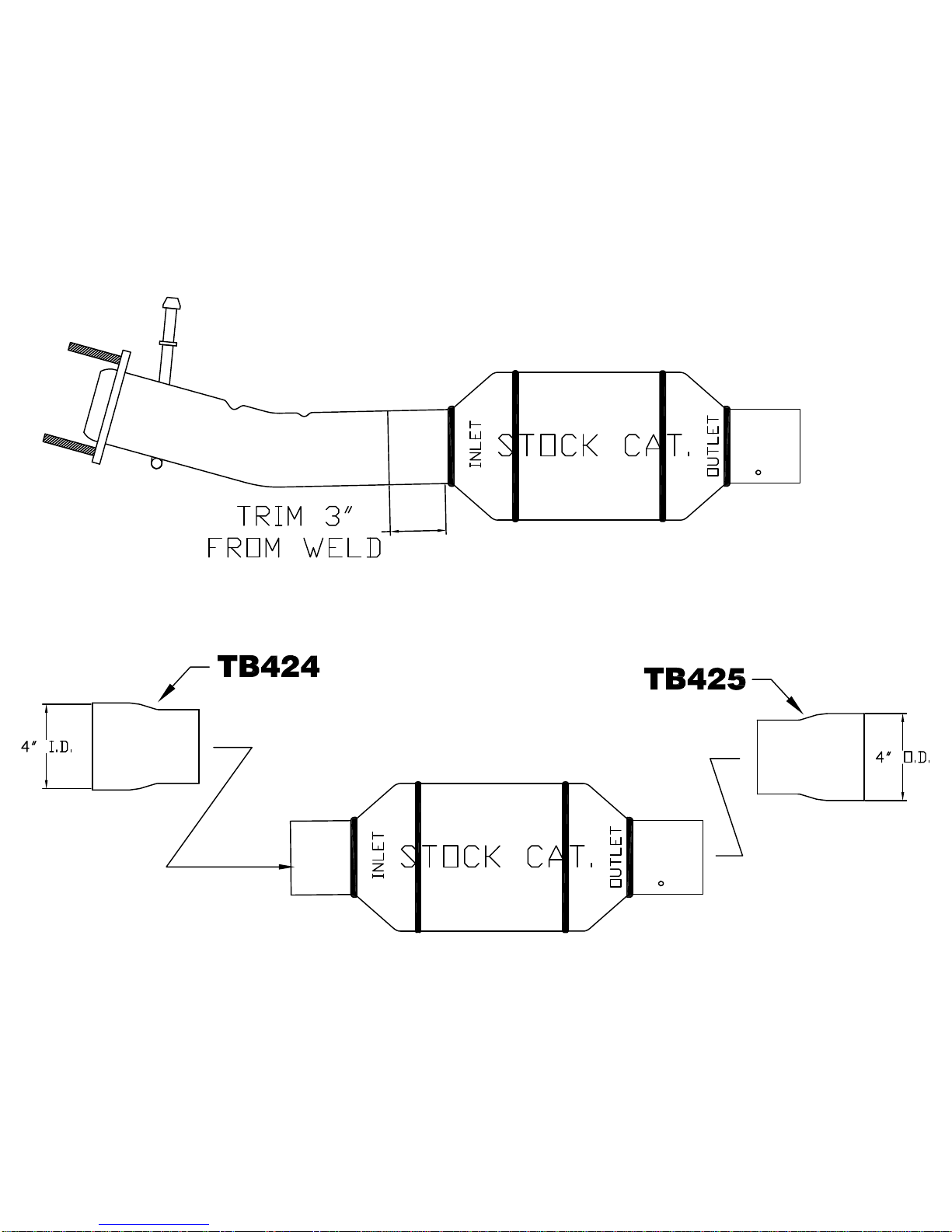
4) Install either the original catalytic converter or the adapter pipe #46046Sonto the rear of the
lower down-pipe and install a provided 4” clamp.See Appendix A below for installing OEM converter.
5) Install the intermediate pipe #46045Sonto the cat or adapter pipe. (Based on production
variations, below is a list of cab designs, and wheel bases to cut your intermediate pipe to fit your
application. Double check all measurements before cutting your intermediate pipe.)
Regular Cab – 4x2 or 4x4
Long Bed – 137.0” W.B.- If not using catalytic converter use pipe #46045S behind down pipe.
If there is a catalytic converter use pipe #46046S and trim to desired length.
Super Cab – 4x2 or 4x4
Short Bed – 141.8” W.B. Trim 36.5” off the rear of pipe #46045S
Long Bed – 158.0” W.B. Trim 20.5” off the rear of pipe #46045S
SuperCrew – 4x2 or 4x4
Short Bed – 156.2” W.B. Trim 22.5” off the rear of pipe #46045S
Long Bed – 172.4” W.B. Trim 6.5” off the rear of pipe #46045S
6) Slip hangers #276HA and #277HA over the intermediate pipe and into the rubber hanger
mounts on the frame. (Some models require only one of these hangers.)
7) Slip hanger #429HA over the muffler inlet neck. Install muffler #14020100-Z onto the rear of
the adapter pipe. Slide the inlet hanger into the rubber hanger mount to support the muffler and
tighten just enough to hold in position.
8) Place a provided 4” clamp onto the muffler outlet and then place front section tailpipe #46047S
into position over the axle and into the muffler outlet. Then, connect the two hangers on the pipe to
the rubber mounts on the vehicle. Tighten the clamp just enough to hold in position.

9) Place a provided 4” clamp over the back of the front tailpipe section. Place rear tailpipe
section #46055Sinto the slip-fit of the front section and attach tailpipe hanger into the rubber mount
on the vehicle. Tighten the clamp just enough to hold in position.
10) On 2003-2004 models the transmission dipstick and tube can now be place back into position
and secured with the original nut.
11) Adjust the position of the muffler and pipes to provide a satisfactory fit and tighten down all
clamped connections securely. After the system is secure, slide the 1/2” hanger keepers on the
round stock sticking through the rubber muffler hangers. This will prevent the hangers from slipping
out of the rubber mounts.
PACKING LIST
QTY DESCRIPTION PART#
1 Muffler 14020100-Z
1 Turbo Down-Pipe Upper 46043S
1 Turbo Down-Pipe Lower 46044S
1 Adapter 46045S
1 Connector Pipe 46046S
1 Front Sec. Tailpipe 46047S
1 Rear Sec. Tailpipe 46055S
1 Parts Kit PK601
1 Downpipe Clamp Hanger 304HA
1 Muffler Inlet Clamp Hanger 429HA
1 Front Pipe Clamp Hanger 276HA
1 Front Pipe Clamp Hanger 277HA
1 3.5” – 4” ID Adapter TB424
1 3.5” - 4” OD Adapter TB425
2 3.5” Band Clamps MC350BS
5 4” Band Clamps MC400BS
7 ½” Hanger Keepers HW503
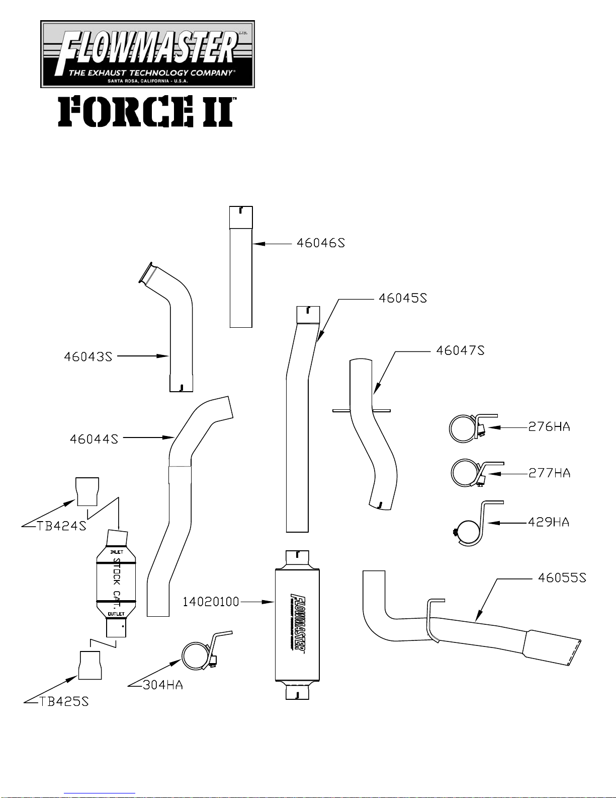
Installation diagram for:
SYSTEM #817546
2003-2007 FORD F-SERIES SUPER DUTY
6.0L POWERSTROKE TURBO DIESEL ENGINE
ALL WHEEL BASES · **AUTOMATIC TRANS. ONLY**
409S®Stainless Steel
Installation diagram for:
SYSTEM #817546
2003-2007 FORD F-SERIES SUPER DUTY
6.0L POWERSTROKE TURBO DIESEL ENGINE
ALL WHEEL BASES · **AUTOMATIC TRANS. ONLY**
FLOWMASTER PERFORMANCE EXHAUST EXHAUST SYSTEMS
Table of contents
Other Flowmaster Automobile Accessories manuals


Popular Automobile Accessories manuals by other brands


MSD Ignition
MSD Ignition 8485 Installation instructions and operators manual

Racks Brax
Racks Brax HD Hitch Series Assembly and mounting instructions

EUFAB
EUFAB 16474 operating instructions

Curt Manufacturing
Curt Manufacturing 31048 installation instructions

BTCPower
BTCPower EVSE 200 KW Installation and user manual

Mont Blanc
Mont Blanc Roof Bars Easy Go 03 Fitting instructions