manuals.online logo
Brands
  1. Home
  2. •
  3. Brands
  4. •
  5. Rockford Fosgate
  6. •
  7. Automobile Accessories
  8. •
  9. Rockford Fosgate CPC05 User guide

Rockford Fosgate CPC05 User guide

12/01 Printed in U.S.A. RFMANTF04
SPECIFICATIONS
WARRANTY INFORMATION
Rating: 1 farad
(CPC10, CPCM10, CPCD10, CPCD10B)
.5 farad
(CPC05, CPCM05, CPCD05, CPCD05B)
VDC: 20V surge
Tolerance: -10% + 50%
Dimensions: 1 farad : 3" x 8.625"
(76.2mm x 219mm)
.5 farad : 3" x 6.5"
(76.2mm x 165.1mm)
Meter Status Caps add 3/4" (19mm)
to height
Digital Status Caps add 1-1/16" (27mm)
to height
ESR: <0.00198Ω@ 120Hz 25°C
Terminals: 1/4" 28 thread
Tools: 3/16" Allen wrench
Connecting Punch
Rockford Corporation
546 South Rockford Drive
Tempe, AZ 85281 USA
USA, (480) 967-3565
Europe, Fax (49) 4207-8101250
Japan, Fax (81) 559-79-1265
Reinforcement Capacitor
CPC05
CPC10
CPCM05
CPCM10
CPCD05
CPCD10
CPCD05B
CPCD10B
Installation &
Application
Manual
Capacitors are nearly indestructible and will provide
years of service if installed and used in accordance
with the instructions in this manual. If this product
should prove to be defective within a period of
ninety (90) days from the date of purchased, contact
your dealer or Rockford Corporation Customer
Service Department at 1-800-669-9899 for
replacement instructions.
In the event the vent is blown or leaking as a result
of switched polarity, the capacitor is not covered by
warranty.
Stripped screws or terminals are not covered by
warranty. Replacements may be obtained at a
resonable cost by contacting Rockford Corporation
Customer Service Department at 1-800-669-9899
DIGITAL STATUS CAP FEATURES
REM
1
6
5
4
3
2
DIGITAL STATUS
ON
REV.
1Remote Turn-On –Attach amp turn-on wire here to
turn capacitor electronics on and off. (The cap is
always charged)
2. Positive Terminal –Connect to Positive (+) side of
vehicle's battery.
3. Voltage Indicator –With the system turned on, the
display will show the DC volts at the capacitor.
4. Reverse Voltage (REV.) Indicator –If it is red,
immediately disconnect the power and check that
positive and negative leads are not reversed. A
buzzer will also sound if this occurs.
5. Power Indicator (ON) –When the LED is green, the
unit is on and functioning properly.
6. Negative Terminal –Connect to chassis ground.
SAFETY INFORMATION
CAUTION: To prevent injury and damage to
the unit, please read and follow
the instructions in this manual.
CAUTION: If you feel unsure about installing
this system yourself, have it
installed by a qualified Rockford
Fosgate technician.
CAUTION: Before installation, disconnect the
battery negative (-) terminal to
prevent damage to the unit, fire
and/or possible injury.
CAUTION: Polarity must be observed and
maintained during installation to
eliminate the possibility of
damaging the capacitor, the battery,
or other associated equipment.
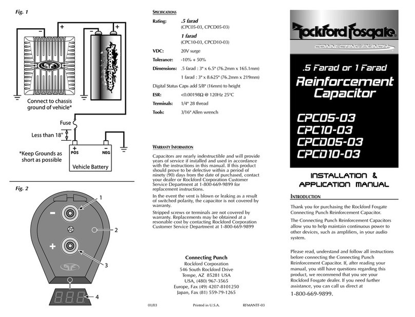
POWER WIRING CONSIDERATIONS
Installation is simple and straightforward. When installing
the capacitor, we recommend using the same gauge wire
as that of the power connection to the amplifier. Ground
the capacitor to the nearest chassis ground using the same
gauge wire as that used for the power connection. It is
strongly recommended the capacitor be fused at the
battery. The fuse value should be the same as that of the
power connection to the amplifier. This fuse should be
installed 18" or less from the battery (See illustration).
If the capacitor is to be used in a multi-amp system, a
power distribution block may be used between the
capacitor and the amplifiers. It should be wired using the
same gauge wire as that of the main system.
The positive side of the capacitor will be connected to the
positive side of the amplifier’s power connection (B+).
CAUTION: Do Not Overtighten Screws!
Stripped or broken terminals are
NOT covered by the warranty
INSTALLATION / MOUNTING
The Rockford Fosgate Reinforcement Capacitor should be
mounted as close to the amplifier as possible, within 18"
(0.5m) of the amplifier, keeping the wire runs short to
reduce voltage losses in the cables. Use the mounting
brackets supplied to secure the capacitor as close to the
amplifier as possible.
The capacitor may be mounted in any position; however,
care should be taken to ensure the venting hole on the top
is unobstructed at all times. This vent is a relief valve
should the electrical polarity become crossed. Should
the capacitor be damaged, fluid will exit from this vent
rendering the capacitor useless.
CAUTION: To prevent damage to the
capacitor, do not install in
locations where it will be exposed
to water, oil or mistreatment.
Install in a dry, safe place within
18" (0.5m) of the amplifier. The
positive lead connects to the
terminal marked with a “+”
symbol. The negative terminal is
not marked. If these wires are
reversed, fluid from inside the
capacitor will leak out of the vent
plug on the top. Do not install a
damaged cap. Use care when
handling damaged capacitors,
treat them like a fully charged
lead acid battery.
CHARGING
DISCHARGING
METER STATUS CAP FEATURES
Mount the charging card on the cap with the “+”end
aligned with the positive (“+”) terminal on the capacitor.
Tighten the terminal screws. Connect the Red wire to a 12
volt positive power source. Connect the Black wire to a 12
volt ground. The green LED on the card will light. When
the light goes out, the cap is charged.
Mount the charging card on the cap with the “+”end
aligned with the positive (“+”) terminal on the cap. Tighten
the terminal screws. Touch the Red and Black wires
together. When the Red LED goes out, the cap is discharged.
!
!
!
!
!
!
s
e
n
s
i
t
i
v
i
t
y
on
voltage level
min max
power
status
remote turn on
(reverse voltage
if red)
cap
1
6
5
4
3
2
1. Charge Level Indicator –With the engine running and
the system turned on at a reasonable level, all bars
should be lit.
2. Negative Terminal –Connect to chassis ground.
3. Sensitivity Adjustment –To set properly, turn engine
on and set system volume level to an average listening
level (90dB). With a small screwdriver, turn counter-
clockwise until at least 3 bars are not lit. Then, turn it
clockwise until all bars are lit again. Stop as soon as
all bars are lit. This is the optimum charge level. If 5 or
fewer bars are lit during loud listening, this indicates
that you may need more capacitance in your system.
4. Remote Turn-On –Attach amp turn-on wire here to
turn capacitor electronics on and off. (The cap is
always charged)
5. Power Indicator –When the LED is green, the unit is
on and functioning properly. If it is red, immediately
disconnect the power and check that positive and neg-
ative leads are not reversed.
6. Positive Terminal –Connect to Positive (+) side of
vehicle's battery.

This manual suits for next models

7

Other Rockford Fosgate Automobile Accessories manuals

Rockford Fosgate RFX8310 Installation and operating manual

Rockford Fosgate

Rockford Fosgate RFX8310 Installation and operating manual

Rockford Fosgate DSR1 User manual

Rockford Fosgate

Rockford Fosgate DSR1 User manual

Rockford Fosgate Polaris PMX-P2 User manual

Rockford Fosgate

Rockford Fosgate Polaris PMX-P2 User manual

Rockford Fosgate ELEMENT READY RFGNRL-K8 Guide

Rockford Fosgate

Rockford Fosgate ELEMENT READY RFGNRL-K8 Guide

Rockford Fosgate Connecting Punch CPC05-03 User manual

Rockford Fosgate

Rockford Fosgate Connecting Punch CPC05-03 User manual

Rockford Fosgate RFRNGR-PMXDK Guide

Rockford Fosgate

Rockford Fosgate RFRNGR-PMXDK Guide

Rockford Fosgate RFYXZ-RSW16 Guide

Rockford Fosgate

Rockford Fosgate RFYXZ-RSW16 Guide

Popular Automobile Accessories manuals by other brands

Pioneer CA-HM-HYU.001OEM installation manual

Pioneer

Pioneer CA-HM-HYU.001OEM installation manual

Diagcar ENIGMA user manual

Diagcar

Diagcar ENIGMA user manual

Hirschmann CGW 70 26 59 SF Series installation instructions

Hirschmann

Hirschmann CGW 70 26 59 SF Series installation instructions

Extang CLASSIC PLATINUM & BLACKMAX 7920 Installation sheet

Extang

Extang CLASSIC PLATINUM & BLACKMAX 7920 Installation sheet

Lippert SolidStep 4.0 owner's manual

Lippert

Lippert SolidStep 4.0 owner's manual

Mont Blanc ISO 11154-M Fitting instructions

Mont Blanc

Mont Blanc ISO 11154-M Fitting instructions

Carefree Alpine Slideout Cover Service manual

Carefree

Carefree Alpine Slideout Cover Service manual

aFe Power SCORPION 79-21003L manual

aFe Power

aFe Power SCORPION 79-21003L manual

Scosche AU2392B manual

Scosche

Scosche AU2392B manual

Discount Car Stereo iP-VOL quick start guide

Discount Car Stereo

Discount Car Stereo iP-VOL quick start guide

Crux Logic ACPBM-77Y manual

Crux

Crux Logic ACPBM-77Y manual

Bn'B Rack Discovery SR-1001 Instruction

Bn'B Rack

Bn'B Rack Discovery SR-1001 Instruction

Subaru F411SFL050 installation instructions

Subaru

Subaru F411SFL050 installation instructions

Whispbar K162W Fitting instructions

Whispbar

Whispbar K162W Fitting instructions

AMP Research BedXTender HD MAX 74842-01A Assembly Installation Guide

AMP Research

AMP Research BedXTender HD MAX 74842-01A Assembly Installation Guide

walser 30864 (S) User instructions

walser

walser 30864 (S) User instructions

Crux BEEBG-25 installation guide

Crux

Crux BEEBG-25 installation guide

Enelion LUMINA quick start guide

Enelion

Enelion LUMINA quick start guide

manuals.online logo
manuals.online logoBrands
  • About & Mission
  • Contact us
  • Privacy Policy
  • Terms and Conditions

Copyright 2025 Manuals.Online. All Rights Reserved.