AEM INFINITY ECU User manual

This product is legal in California for racing vehicles only and should never be
used on public highways.
WARNING:
!
This installation is not for the electronic novice or the PC illiterate!
Use this system with EXTREME caution! If you are not well versed in
electronics and vehicle instrumentation or are not PC literate, please
do not attempt the installation. Refer the installation to an AEM
trained tuning shop. A list of AEM trained tuning shops is available
at www.aemelectronics.com/dealer_locator.php or by calling 800-
423-0046. You should also visit the AEM Performance Electronics
Forum at http://www.aemelectronics.com.
NOTE: AEM holds no responsibility for any engine damage that
results from the misuse of this product!
NOTE: All supplied AEM calibrations, Wizards and other tuning
information are offered as potential starting points only. IT IS THE
RESPONSIBILITY OF THE ENGINE TUNER TO ULTIMATELY
CONFIRM IF THE CALIBRATION IS SAFE FOR ITS INTENDED USE.
AEM holds no responsibility for any engine damage that results from
the misuse or mistuning of this product!
AEM Performance Electronics
2205 126th Street Unit A, Hawthorne, CA. 90250
Phone: (310) 484-2322 Fax: (310) 484-0152
http://www.aemelectronics.com
Instruction Part Number: 10-7100
2013 AEM Performance Electronics
INFINITY
Quick Start Guide


RevC 07/15/13 Page 3
KIT CONTENTS
1 x INFINITY ECU
1 x QUICK START GUIDE
2 x USB CABLE
1 x 4GB FLASH MEMORY DEVICE
10 x ECU HARNESS TERMINALS
IMPORTANT
BACKGROUND
INFO
The Infinity platform is very different from previous generation AEM EMS products. The
hardware (circuit board assembly) is designed around averyadvanced automotive
grade microcontroller (processor or “chip”). Several layers of software reside on this
chip that allowfor real time firmware programming without the need to write computer
code. This technology hasallowed AEM to develop advanced control modelsnever
before usedon other AEM EMS products. We’ve listened to our customers over the
years and have attempted to simplify the tuning process by employing an airflow based
fuel control model eliminating many of the lookup and trim tables from previous
generation ECUs. The look andfeel is very different and it may take some time to
adjust to the newtuning environment.
Our new tuning tool, InfinityTuner is alsoabrand new product built from the ground up
to interface with the new hardware. It features amodular design that allowsusers and
developers to build completely customized templates and even design “plug in”
applications that can automate many tuning tasks. Unlike previous AEM Setup Wizards
in older products like AEM Pro and AEM Tuner, the InfinityTuner SetupWizard “plug in”
is acompletely stand-alone application that will evolve with InfinityTuner. It is much
more integrated with the ECU hardware and performscomplex validation checks for all

RevC 07/15/13 Page 4
requested changes.
Among other things, InfinityTuner is apowerful math processor. Special features allow
usersto create completely custom conversion channelsfor table data. Virtually any
function can be employed to display data in different formats or units. Math functions
are alsoused for table edits. ANY MATH function can be usednot just alist of pre-
defined selections. Advanced userswill really enjoy the flexibility thisfeature adds.
Abuilt-in logging playback/controls synchronization feature allowstuners to view live
plot data and make changes to their calibration values on the fly, knowing exactly where
the ECU wasaccessing table data. For more detailed post processing of data, AEM
offers itsnew analysis package, AEMdata.
RevC 07/15/13 Page 5
InfinityTuner: Install
Software Installation
All current InfinityTuner software installations are available for download from the AEM
Performance Electronics site at http://www.aemelectronics.com/catalog-software-
downloads-72/
1. Run the setup.exe file from within the zip file. Hit Next> and follow the instructions on
each page.
2. Read and accept the terms of agreement and pick your desired location for
InfinityTuner to be installed. Hit Next> and allow the software to complete installation.
3. You may now exit the InfinityTuner installer. To use InfinityTuner with an ECU
connected, you will need to install the necessary USB drivers. See Device Driver
Installation below.
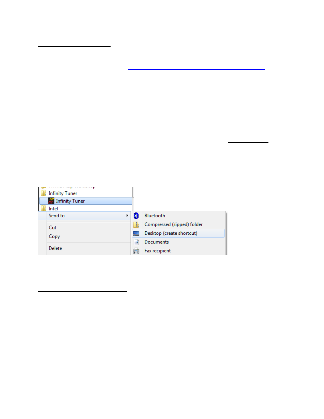
4. If desired, add a desktop link for InfinityTuner. Click the Windows Start button and
navigate to All Programs\InfinityTuner. Right click on the InfinityTuner link and select
Send to>Desktop (create shortcut).
Device Driver Installation
For these next steps the Infinity ECU will need to be installed and powered up.
Refer to your harness instructions details. You will need the ignition key in the on
position. Connect your computer to the ECU via the USB cable.

RevC 07/15/13 Page 6
2. Open the device manager. Directions shown below for Windows 7 and Windows XP:
Windows 7 Windows XP
For Windows 7 users, you may simply search for and open the “Device
manager” using the search bar under the start tab. You should see a window that
looks similar to the Device manager shown above on the left hand side.
For Window XP users, right click on “My Computer” under the start tab. Click on
“Manage”. Select “Device Manager”. You should see a window that looks similar
to the Device manager shown above on the right hand side.
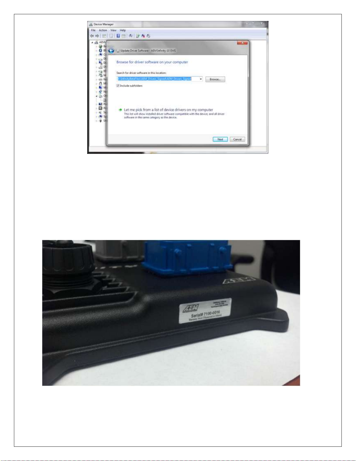
Next look for a device labeled “AEM Infinity-10 EMS” (or similar). It may be listed
under “Other devices”. Right click “AEM Infinity-10 EMS” and select Update
Driver Software. When prompted with “How do you want to search for driver
software?” select the second option, “Browse my computer for driver software
Locate and install driver software manually”. USB driver files can be downloaded
from http://www.aemelectronics.com/catalog-software-downloads-72/
Save this file in an easy to find location like the Windows Desktop. You will need
this link below.

RevC 07/15/13 Page 7
**If AEM Infinity-10 EMS does not appear on the list please verify that the USB plug is
securely plugged into your computer and the ECU. Also make sure that the
ECU is in fact powered up and connected correctly. If problem persists, try turning the
key off and then back to the on position or try a different USB port on the PC.
4. Hit Browse and select the “AEM_Drivers_Signed” folder saved above. Make sure to
have the “Include subfolders” box checked. Hit Next. This will install the driver software
onto your computer. You will now be able to use the “Connect to USB” option in
InfinityTuner.
RevC 07/15/13 Page 8
AEM
recommends
restarting
your
PC
after
making
changes
to
your
device
driver
installation.
Note: To confirm the driver installed properly you can return to your device manager
window. The “AEM Infinity-10 EMS” device will now be recognized and fall under the tab
“AEM EMS Controllers”.
Infinity ECU: Serial Number
RevC 07/15/13 Page 9
All Infinity ECUs are serialized. Be sure this identification tag stays intact. Write the
numberdown to be safe. Infinity ECU’s are programmed with cryptographically secure
firmware filesand each ECU hasaunique file set. The serial number is usedto identify
the correct files for your ECU.
AEM Infinity Account Registration
Infinity ECUs must be registered before use. The following procedure describes how to
register your new Infinity ECU. The aeminfinity.com site will always have the latest
software available for your system.
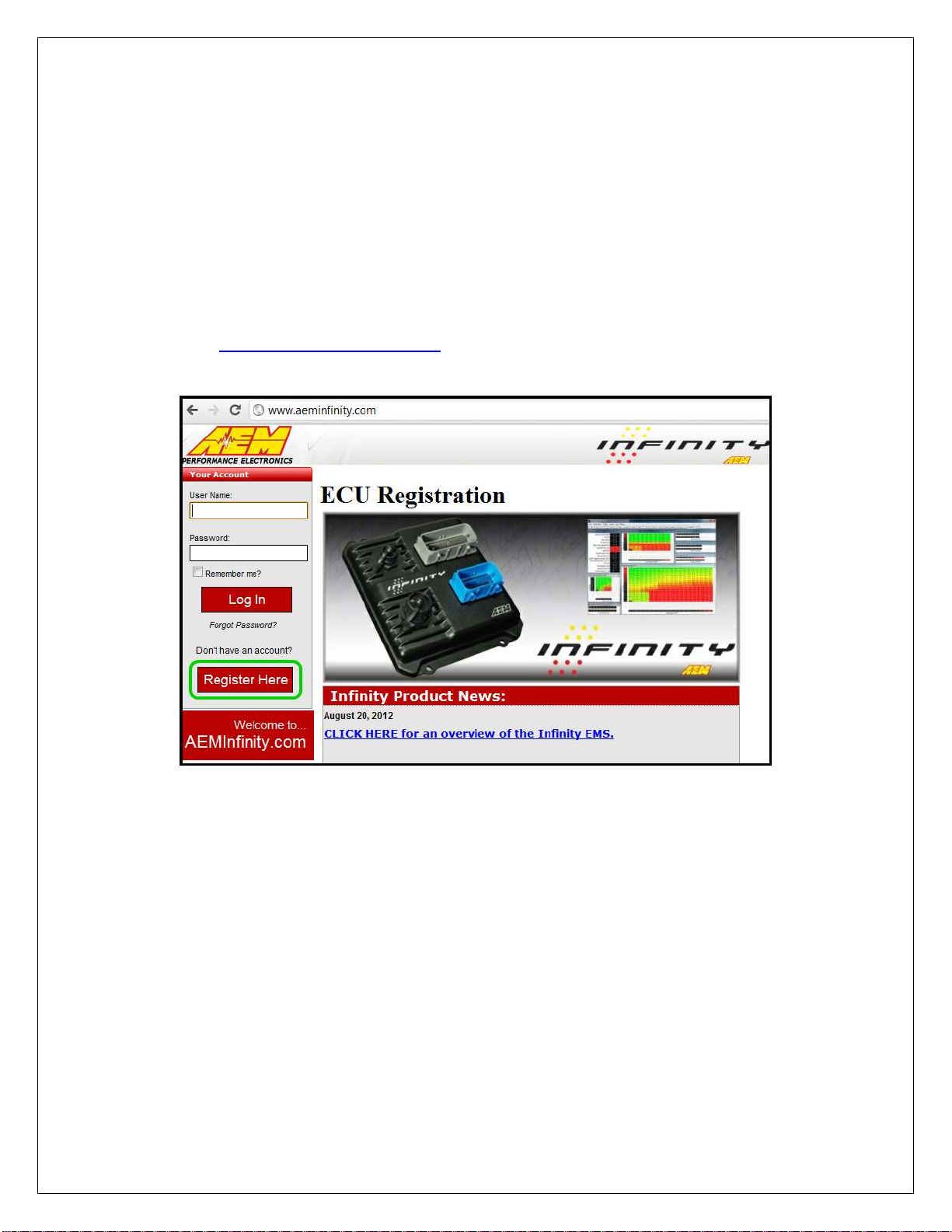
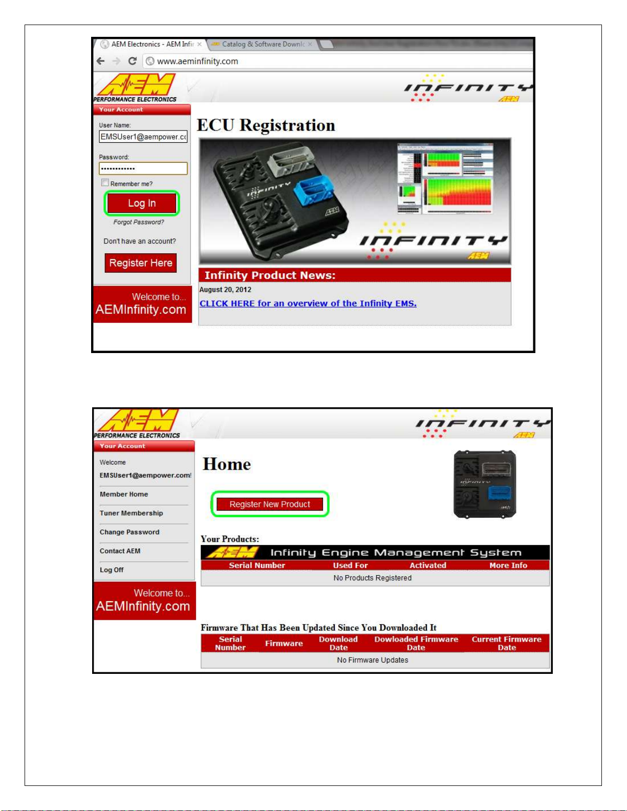
1) Go to http://www.aeminfinity.com
a. Click on “Register Here” button
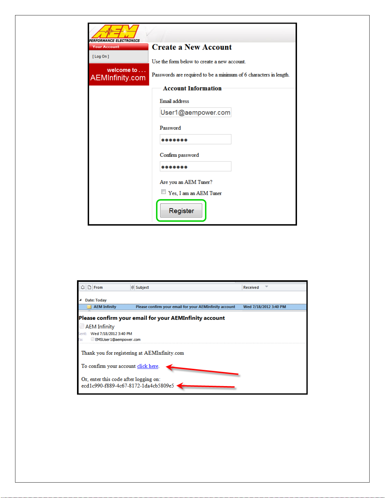
2) Enter required information
a. Click the “Register” button
RevC 07/15/13 Page 10
3) A confirmation email will be sent to the supplied email address. Choose one of
the following options:
a. Click on the “click here” link
b. Or, copy the code and enter it into the Confirmation Code Box.
4) After entering the code, click on the “Confirm” button

RevC 07/15/13 Page 12
2) Click on the “Register New Product” button
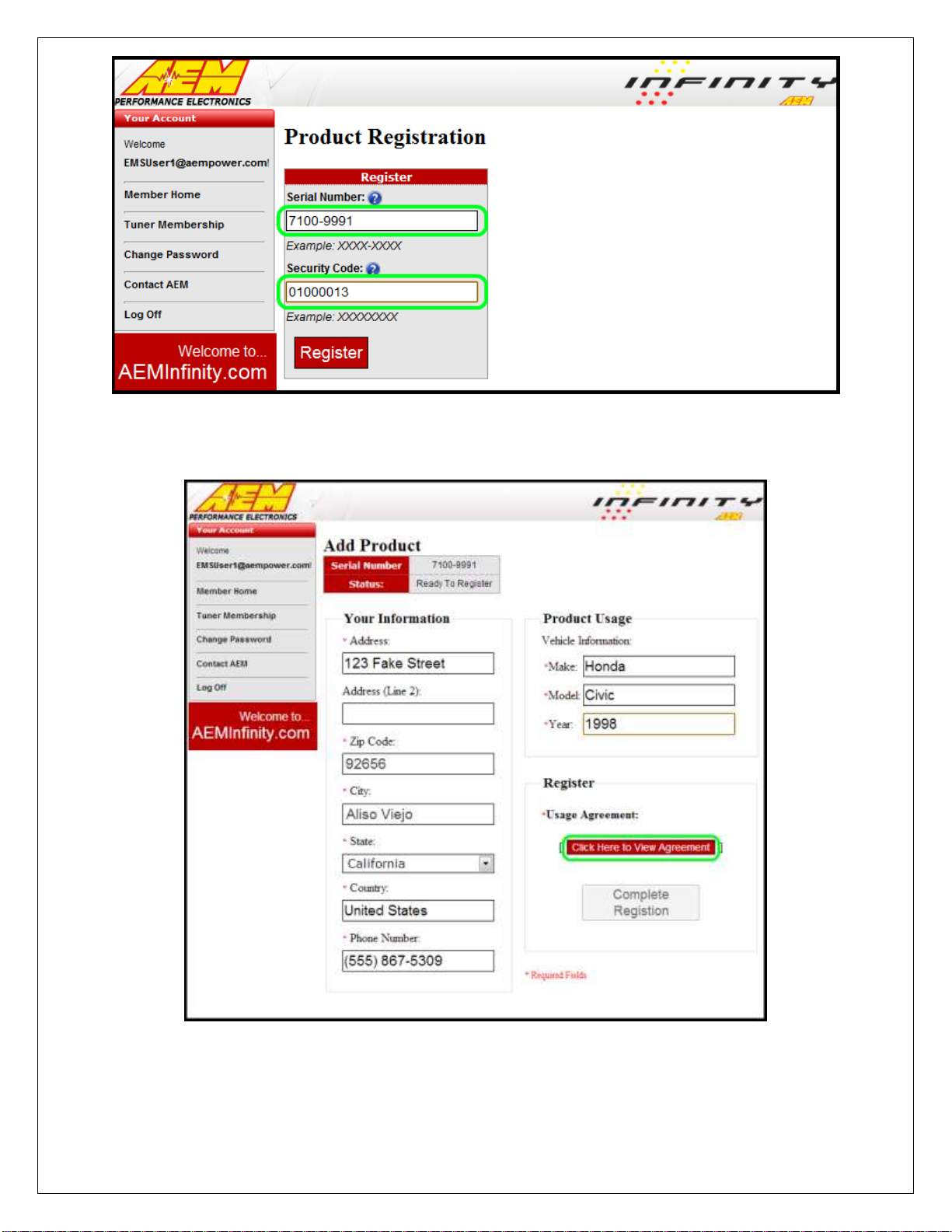
3) Enter the Serial Number and Security Code
a. Serial Number found on sticker on ECU case
b. Security Code included in ECU packaging
RevC 07/15/13 Page 13
4) Enter Product Registration Information
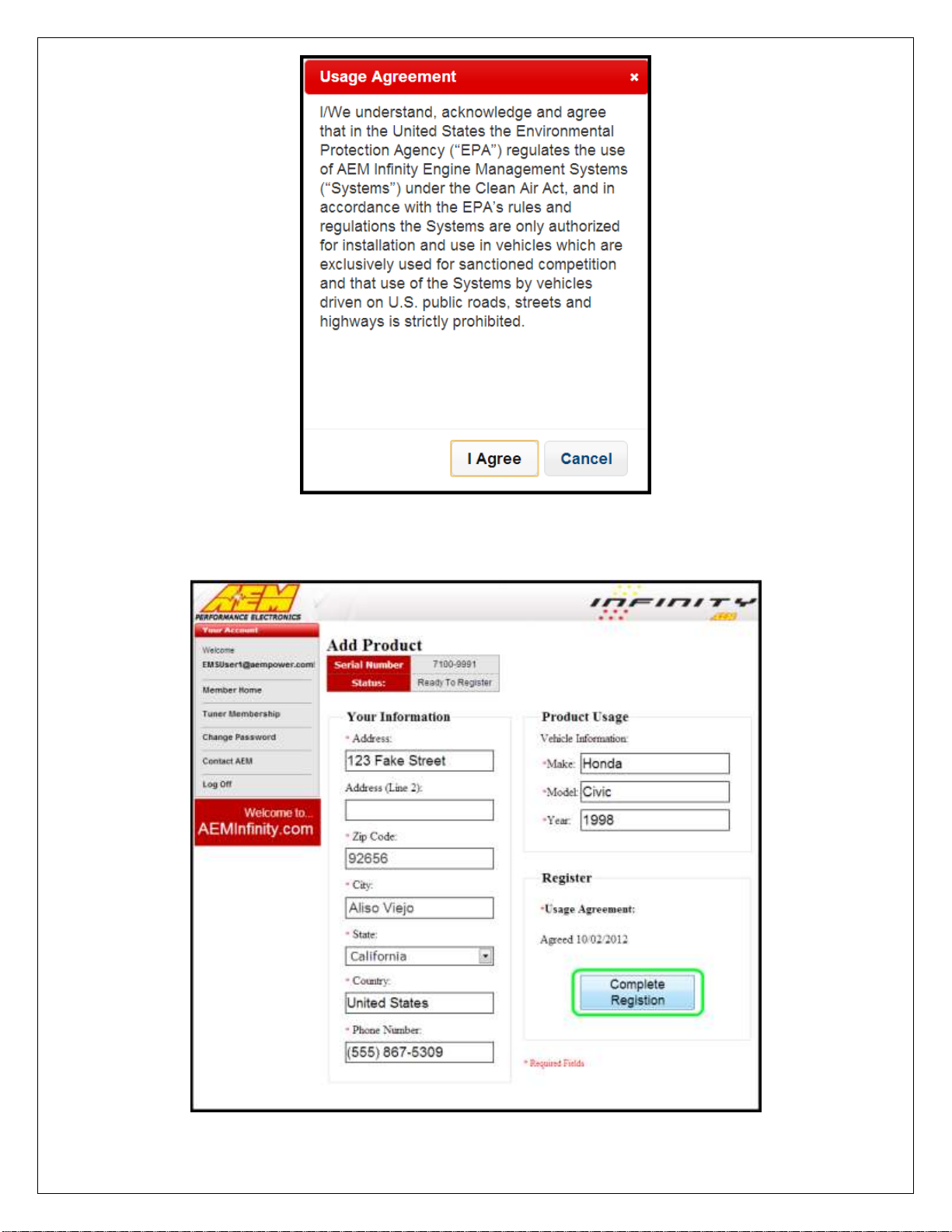
a. You must first read and accept the Agreement
5) Read and then accept Usage Agreement by selecting the “I Agree” button.
RevC 07/15/13 Page 14
6) Click the “Complete Registration” button once the Usage Agreement has been
accepted.


RevC 07/15/13 Page 16
3) Locate the desired Configuration file and click the “Download” button.
a. The Configuration file includes the Firmware and the Configuration files as
a .pakgrp file
4) Save the .pakgrp file in the AEM InfinityTuner directory
a. C:/Program Files (x86)/AEM/InfinityTuner

RevC 07/15/13 Page 17
5) Connect to InfinityTuner
a. Plug the USB cable from the ECU into your PC’s USB port
b. Open InfinityTuner, If the wiring harness is installed correctly and ignition
power is on, InfinityTuner should connect automatically. If not, then click
the Connection drop-down list and select “Connect to USB”
6) Click the Target drop-down list and select “Upgrade firmware…”
7) The ECU should not be running an engine at this time. Select “Yes” when the
warning message appears.
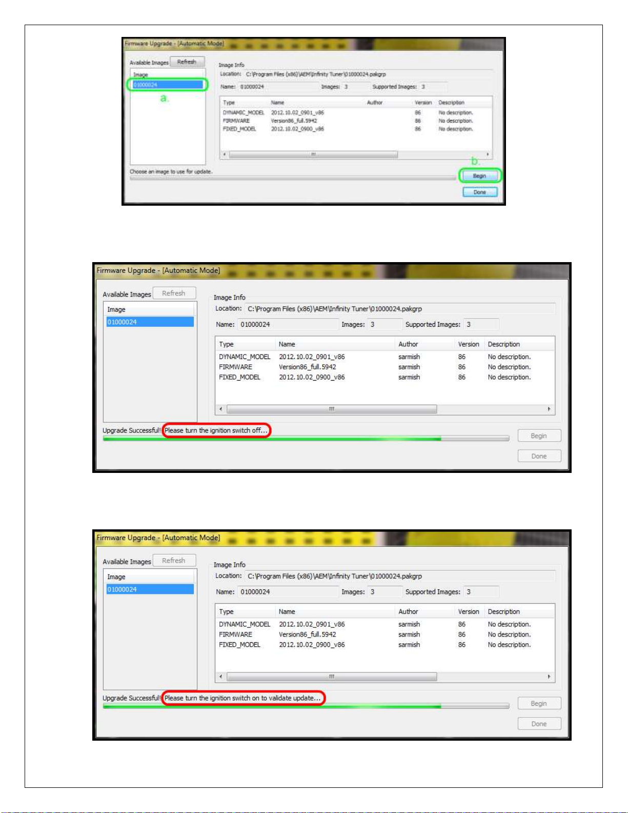
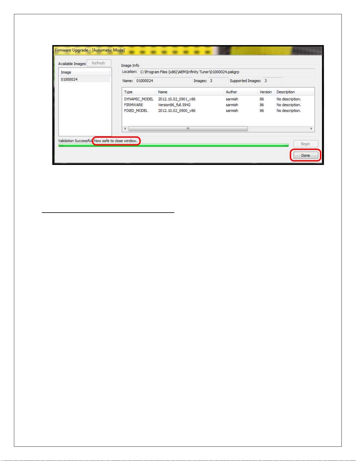
8) Begin the Firmware Upgrade process. Note: The firmware upgrade utility is
periodically updated and may not match the descriptions below. In the event of a
conflict, please follow the instructions included in the dialog windows themselves
or any supplemental documentation provided by AEM.
a. Select the desired Configuration “Image” on the left
b. Click the “Begin” button to start the upgrade process
RevC 07/15/13 Page 18
9) Follow the message at the bottom, and turn the ignition switch OFF when
instructed to do so.
10)Follow the message at the bottom, and turn the ignition switch back ON when
instructed to do so.
RevC 07/15/13 Page 19
11)When the message at the bottom indicates that it’s safe to close the window,
click the “Done” button.
InfinityTuner: Calibration Data
Connecting and Saving the Session File
The default calibration data provided by AEM should be sufficient to start an engine with
similar displacement, sensor setup, and injectors. Every vehicle must be tuned before
use.
1) With the Ignition in the ON position and InfinityTuner Running, click on the
Connection menu item and select Connect to USB from the dropdown list. A
progress bar will be displayed as the laptop gets the calibration info from the ECU.
2) Open a layout file by clicking on the Layout menu item and select Open. Layout files
have a .itlyt extension and should be saved in the My
Documents\InfinityTuner\Layouts folder.
3) Save the session file by selecting File –Save session. Session files have a .itssn
extension and should be saved in the My Documents\InfinityTuner folder.

RevC 07/15/13 Page 20
InfinityTuner: Setup Wizard
Setup Wizard
The ECU setup wizard is designed to simplify the initial configuration of the Infinity ECU.
AEM recommends using the wizard only when connected to the ECU via USB
with the power on. Most of the setup wizards require the engine to NOT be running.
Exceptions will be clearly stated in the function descriptions.
The setup wizard contains general and detailed descriptions with each major function.
The most imperative functions are discussed below. Use the descriptions in the wizard
to assist in the completion of all other setup features.
1) With the laptop connected to the Infinity ECU via USB and InfinityTuner connected,
Go to the Plug-ins menu at the top of the InfinityTuner layout and select Wizards >
Setup Wizard.
2) Setup: Basic
Select the appropriate engine descriptions for Displacement, Number of cylinders,
cycle type, Ignition type and firing order. Choose the following Airflow Calculation
Method: VE (using MAP sensor), 0-5V MAF (analog MAF sensor), or Frequency
MAF (Digital MAF sensor). Then describe the Load Axis vs. RPM for Main Spark
Map and VE Table (if using VE for Airflow Calc Method). MAP [kPa] is a typical
selection for most cars using the VE airflow calculation method.
3) Setup: Cam/Crank
Choose the Cam/Crank timing type that will be used. The description field notes
important information about edge selections and wiring requirements.
4) Setup: Ignition Sync
The Ignition Sync is used to ensure that the timing measured at the crankshaft
matches the channel displayed in InfinityTuner. This step is crucial and must not
be skipped.
Two separate procedures are required depending on the Infinity application: Plug
and Play, or Universal Application.
Plug and Play
a. In the Ignition Sync wizard, select the checkbox “Lock ignition timing at” and
set the “degrees BTDC” (10.0 deg BTDC is the default).
b. Start the engine and use a timing light to verify that the crankshaft timing
matches the locked ignition timing set point (10.0 deg BTDC if using the
default setting).
c. If there is a deviation between the locked set point and the actual timing
observed with the timing light, use the Sync Adjustment arrows to match the
wizard-displayed value with the actual value. As the Sync Adjustment arrows
are advanced or retarded, the timing observed on the crankshaft will change,
while the “Lock ignition timing at 10.0 degrees BTDC” will remain constant.
Other AEM Automobile Accessories manuals


