Flowserve GESTRA GAV 54F Manual

1
GAV 54F
Installation & Operating
Instructions 819025-00
English
Shut-Off Valve
E N

2
Contents
Important Notes
Usage for the intended purpose .................................................................................... 4
Safety note .................................................................................................................. 4
Danger........................................................................................................................ 4
Attention ..................................................................................................................... 4
PED (Pressure Equipment Directive) .............................................................................. 4
ATEX (Atmosphère Explosible)....................................................................................... 4
Explanatory Notes
Scope of supply ........................................................................................................... 5
Description .................................................................................................................. 5
Function...................................................................................................................... 5
Attention ..................................................................................................................... 5
Danger........................................................................................................................ 5
Technical Data
Pressure & temperature ratings .................................................................................... 6
Attention ..................................................................................................................... 6
Corrosion resistance .................................................................................................... 6
Design
GAV 54F...................................................................................................................... 7
Key ............................................................................................................................. 7
Installation
GAV 54F...................................................................................................................... 8
Attention ..................................................................................................................... 8
Danger........................................................................................................................ 8
Attention ............................................................................................................... 8 – 9
Danger........................................................................................................................ 9
Attention ..................................................................................................................... 9
Installation notes.......................................................................................................... 9
Danger...................................................................................................................... 10
Commissioning Procedure
GAV 54F ................................................................................................................... 10
Danger...................................................................................................................... 10
Attention ................................................................................................................... 11
Functional test ........................................................................................................... 11
Attention ................................................................................................................... 11
Page

3
Contents
Maintenance
GAV 54F.................................................................................................................... 12
Attention ................................................................................................................... 12
Danger...................................................................................................................... 12
Spare Parts
GAV 54F.................................................................................................................... 13
Attention ................................................................................................................... 13
Decommissioning
Danger...................................................................................................................... 13
Disposal .................................................................................................................... 13
Transport and Storage
Transport................................................................................................................... 14
Attention ................................................................................................................... 14
Storage ..................................................................................................................... 14
Hoisting the valve for installation into horizontal pipeline ............................................... 15
Hoisting the valve for installation into vertical pipeline................................................... 15
Page

4
Usage for the intended purpose
Use the shut-off valve GAV 54 F only for isolating and throttling neutral gases, steam,
vapours and liquids within the specified pressure and temperature ratings and check the
corrosion resistance and chemical suitability for the application in question.
Safety note
The equipment must only be installed and commissioned by qualified and competent staff.
Retrofitting and maintenance work must only be performed by qualified staff who –
through adequate training – have achieved a recognised level of competence.
Danger
The valve is under pressure during operation.
When loosening flanged connections, sealing plugs or stuffing box connections,
hot water and steam will escape.
This presents the risk of severe scalding all over the body!
Before carrying out installation and maintenance work make sure the system is
depressurized. Isolate the valve from both upstream and downstream pressure.
The valve becomes hot during operation. Risk of severe burns to hands and arms.
Before carrying out installation and maintenance work make sure that the steam
trap is cold.
Sharp edges on parts present a danger of cuts to hands.
Always wear industrial gloves when replacing valves or parts of valves.
Danger of bruising! During operation moving parts can pinch one's hands or fingers,
causing severe injuries. Do not touch moving parts.
Attention
The name plates specify the technical properties of the devices.
Do not commission or operate any item of equipment that does not bear its specific name
plate.
PED (Pressure Equipment Directive)
The equipment fulfills the requirements of the Pressure Equipment Directive PED 97/23/EC.
For use with fluids of group 1 and 2.
With CE marking (apart from equipment that is excluded from the scope of the PED as
specified in section 3.3).
ATEX (Atmosphère Explosible)
The equipment does not have ist own potential source of ignition and is therefore not
subject to the ATEX Directive 94/9/EC. Applicable in Ex zones 1, 2, 21, 22 (1999/92/EC).
The equipment is not Ex marked.
Important Notes

5
Explanatory Notes
Scope of supply
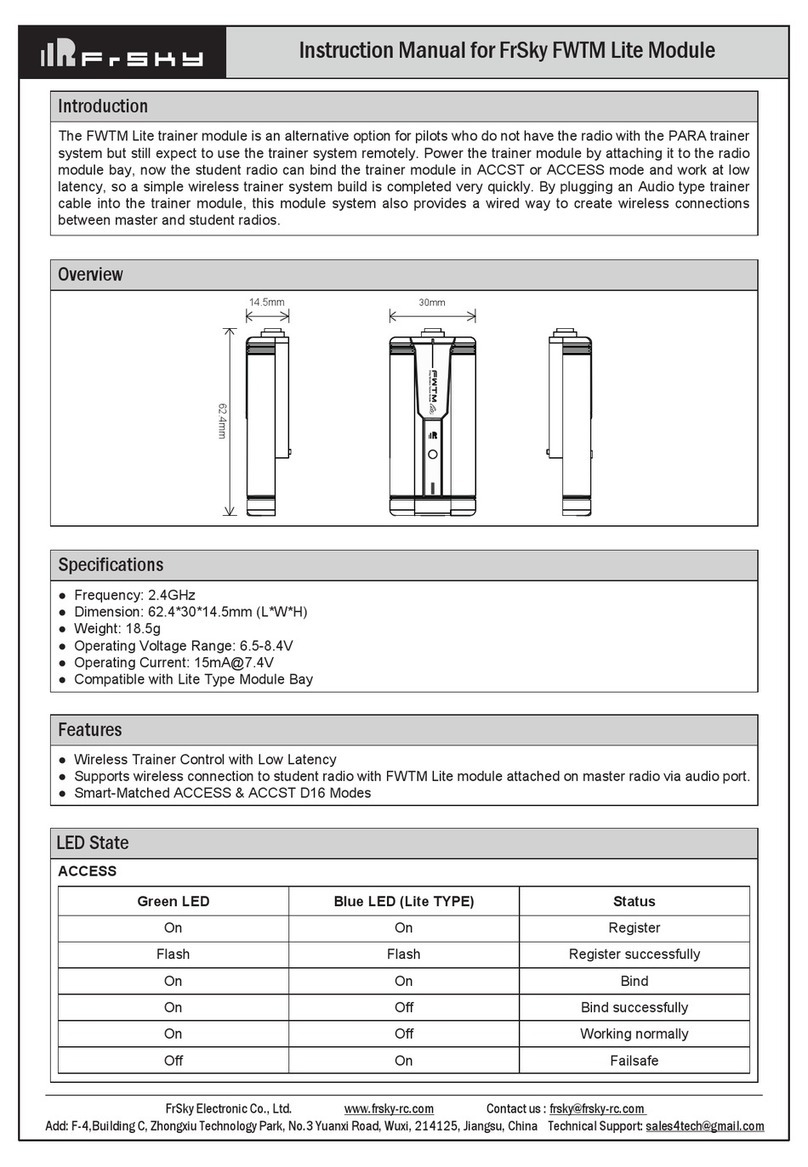
GAV 54F
1 Shut-off valve GAV 54F
1 Installation manual
Description
Maintenance-free bellows-sealed shut-off valve with straight-through body, flanged to
EN 1092-2. The shut-off valve is equipped with a stainless steel bellows seal
and a safety stuffing box made from pure graphite.
Shut-off valves from DN 15 to DN 100 are fitted with a throttling plug as standard.
DN125 to DN300 valves come with a flat plug as standard. The handwheel features a
non-rising stem and a
locking device.
Function
To close the shut-off valve turn handwheel to the right and to open it turn handwheel to the
left. Direction symbols are found on the top of the handwheel.
The valve stem is sealed off by means of a stainless steel bellows and a safety
stuffing box made from pure graphite.
Use the locking device to lock the handweel in place by turning it to the right until it hits
the stop. When supplied the handwheel is not locked in place.
Attention
Incorrect operation of the valve may have a substantial impact on the entire system, for
example:
Leakage of the fluid
System / machine brought to a standstill
Impairment / reduction / increase of the system's / machine's function / effect
Danger
When delivered ex factory, the safety stuffing box is not fully tightened. In the event of the
bellows failure, the stuffing box screws (safety stuffing box) must be tightened in order to
avoid fluid leakage (observe dange note on page 4!). The stem seal with bellows is main-
tenance free.

6
Technical data
Pressure & temperature ratings
GAV 54F, flange PN 16, EN 1092-2
PS (max. admissible pressure) [barg] 16 16 14.4 12.8 11.2 9.6
TS (max. admissible temperature) [°C] 20 120 150 200 250 300
PS (max. admissible pressure) [psig] 232 232 208 185 162 139
TS (max. admissible temperature) [°F] 68 248 302 392 482 572
ΔP (admissible differential pressure) [bar] 16
[psi] 232
Attention
If the following differential pressures are exceeded, a pressure balance plug is required.
DN 200 250 300
ΔP (admissible differential
pressure)
[bar] 12 9 6
[psi] 174 130 87
The pressure balance plug only takes effect when pressures builds up above the valve
plug. As a consequence, the flow through the valves is reversed. Note that the embossed
flow direction arrow is reversed.
Corrosion resistance
If the equipment is used for the intended purpose, its safety is not impaired by corrosion.

7
Design
GAV 54F
0
9
8
7
6
5
4
3
2
1
Key
1Handwheel
2Stem
3Body cover
4Gland packing
5Hexagon-head screws
Fig. 1
6Joint ring
7Bellows
8Valve plug
9Seat ring
0Body

8
GAV 54F
Responsibility for positioning and installing the valves always lies with the engineering
company, construction company or operator/user. Planning and installation errors may
impair the reliable function of the valves and pose a substantial safety hazard.
For this reason it is particularly important to observe the following:
Attention
The piping must be laid such that detrimental thrust and torsional forces are kept away
from the valve body during installation and operation to avoid both leakage and damage to
the body.
The caps on the connection ports, if any, shall be removed immediately prior to installation.
The mating flange faces must be clean and undamaged .
Danger
The gaskets on the flange faces must be properly centered.
Only fasteners (for ex. to DIN EN 1515-1) and flange gaskets (for ex. to DIN EN 1514)
made of materials suitable for the respective valve size may be used.
For the flange connection between valve and pipe use all flange bolt holes provided.
Attention
When using steel flanges to DIN EN 1092-1 in conjunction with cast iron valves with
flanges machined to DIN EN 1092-2, make sure that for nominal diameter
DN 65 the mating flanges are fitted offset by 22.5° to prevent an oblique position of the
valve.
This procedure is required by the difference in the number of bolt holes: DIN EN 1092-1
specifies 8 holes for steel, whereas DIN EN 1092-2 specifies only 4 holes for cast iron.
DN 65 (steel / steel):
DIN EN 1092-1 with DIN EN 1092-1,
Bolts through 8 holes
DN 65 (steel / cast iron):
DIN EN 1092-1 with DIN EN 1092-2,
Bolt hole circle to DIN EN 1092-1 turned
through 22.5°, bolts through 4 holes,
4 holes free
Installation
Fig. 2

9
Attention - continued -
When the valve is installed outdoors, sufficient weather protection must be provided to
prevent corrosion and other damage caused by penetrating moisutre.
When painting pipes or equipment, do not apply paint to the stem and plastic components
(valve function will be impaired).
If construction work is still in progress, the valves must be protected against dust, sand
and building material (cover with suitable material).
Neither the valve nor its actuating elements (e. g. handwheel, actuator, cover) must be
subjected to excessive loads (e. g. used as footholds).
The valve body and/or cover must not be subjected to any sudden impacts (with tools, for
example) as they could be destroyed.
Danger
For safety reasons, valves and piping systems operated at high (> 50 °C) or low (<0 °C)
temperatures must be insulated, or a warning sign must point out the risk of personal
injury involved when touching the hot or cold components.
Attention
If there is a risk of condensation water or ice formation, for example in air-conditioning,
cooling and refrigerating systems, it is important to ensure that the complete valve
including handwheel, if required, is provided with a proper diffusion-tight insulation. The
formation of ice introduces the risk of actuator blocking.
Installation Notes
Flow through shut-off valves should be in the direction of the embossed arrow on the valve
body. An alternating direction of flow is permissible with the standard plug but not with
the pressure balance plug. If equipment from DN 200 exceeds the following differential
pressures, a pressure balance plug is required.
DN 200 250 300
ΔP (admissible differential
pressure)
[bar] 12 9 6
[psi] 174 130 87
The pressure balance plug only takes effect when pressures builds up above the valve
plug. As a consequence, the flow through the valves is reversed (the embossed flow
direction arrow is reversed).
Installation - continued -

10
Danger
The valves should not be installed with the stem pointing downwards to prevent dirt
deposits between the folds of the bellows which might cause valve failure.
In steam service, the valve must not be installed with the stem pointing downwards
(risk of steam hammer due to condensate collecting in the valve neck).
Shut-off valves must be installed in the line so that the fluid enters the valve beneath
the disc and flows out above the disc. However, they can also be installed in lines with
alternating flow.
If the valves are to be used for throttling applications, a throttling valve disc (standard
variant DN 15 – 100) must be used.
In valves with pilot plug, the flow direction must correspond to the direction indicated by
the arrow on the valve. Valves with pilot plug must always be installed so that the pressure
to be sealed off lies above the plug.
Installation - continued -
GAV 54F
Prior to commissioning / start-up compare the material, pressure and temperature data
on the valves with the operating conditions of the piping to check the material's chemical
resistance and stability under load.
Danger
Venting the valve by undoing the bonnet / cover bolting or removing the stuffing box
packing is dangerous and therefore not permitted.
It is generally not allowed to use lamellar graphite cast iron (EN-JL1040) in systems where
surge pressures might develop, since this material does not withstand pressure surges
and, therefore, the valves may be damaged or destroyed. In such cases valves made of
nodular cast iron (EN-JS1025) or steel shall be used.
In new systems and particularly after repair, the complete piping must be thoroughly
flushed with the valves fully opened so that particles and/or welding beads that might
damage the seat/disc interface are removed.
Valve actuation
Viewed from above, the valve is closed with a clock-wise turn of the handwheel, and
opened with a counter-clockwise turn.
Direction symbols are found on the top of the handwheel.
Commissioning Procedure

11
Attention
As the valve can be damaged by applying excessive forces, it is not allowed to use
additional levers to move the handwheels of nominal valve sizes up to and including
DN 125.
On all nominal sizes greater than DN 125, suitable additional levers may be used up to the
following torque limits:
DN 150 200 250 300 350
Mt[Nm] 120 200 200 200 200
Hex. head WAF 36 46 46 46 46
The above values do not apply in the event of foreign matter or fluid deposits in the seat/
disc interface.
Note that additional levers must not be used in the immediate vicinity of the position
indicator.
Shut-off valves are normally used in such a way that they are either fully open or fully
closed.
For intermediate positions, variants with throttling disc should be fitted, unless throttling
discs are installed as a standard feature.
Performing throttling operations without a throttling disc may result in an excessive noise
level, excessive wear or even destruction of the valve by cavitation.
Functional test
The following functions must be checked:
Check the shut-off function of the installed valve prior to commissioning / start-up by
opening and closing it several times.
The bonnet/cover bolting shall be checked for tightness after the first loading or heating
up of the valves.
If required, the bonnet bolting must be gradually re-tightened cross-wise and evenly in a
clock-wise direction.
Attention
Before tightening the bonnet bolting open the valve by approximately two full turns of the
handwheel to avoid stress or distortion.
Re-tightening the bonnet/cover bolting is particularly important for valves installed in heat
transfer systems.
Commissioning - continued -

12
GAV 54F
Repair and maintenance work must only be performed by skilled, properly trained personnel.
It is imperative that the following safety instructions and the danger note on page 4 be
observed for all servicing and maintenance work to be performed.
Attention
Always use suitable tools and original spare parts – even if sudden emergencies arise –
to ensure proper functioning of the valve.
Valve dismantling
Before removing the complete valve from the pipeline or before repairing or servicing the
valve, i. e.
before undoing the flange bolting between valve and pipe
before undoing the bonnet bolting
before undoing the stuffing box screw at the stuffing box ring
if the bellows is defective or there is fluid leakage in this area
before removing any sealing, opening or vent plugs
valve pressure must be released and the valve must be allowd to cool down such that the
temperature is below the fluid's vaporization temperature in all areas in contact with the
fluid in order to effectively prevent any risk of scalding.
Danger
Danger to life: Never open a valve under pressure!
If toxic or easily inflammable fluids were handled, or fluids whose residues may cause
corrosion in conjunction with humidity, drain the valve and flush or vent it. If required, wear
safety clothing and a protecive mask!
Depending on the installation position, fluid residues may be left in the valve; these must
be collected and properly disposed of.
Prior to any transport, flush and drain the valve thoroughly.
All valve components have been designed to be largely maintenance-free.
The materials of the moving parts have been selected for minimum wear. To ensure
operating reliability and to reduce repair costs, all valves should however be checked
regularly, i. e. they should be actuated (opened/closed) at least once or twice a year, in
particular those valves which are rarely used or difficult to access.
The operator / user is responsible for fixing appropriate inspection and servicing inter-
vals as required by the service conditions of the valves. The service life of valves can be
prolonged by:
Lubricating the moving parts such as stem and stem nut using standardized lubricants
to DIN 51825.
Maintenance

13
GAV 54F
No spare parts are available for shut-off valves up to DN 150.
A faulty shut-off valve must be discarded and replaced by a new one.
Attention
All repair and maintenance work shall be performed by skilled, properly trained personnel
using suitable tools and original spare parts. We recommend to have this work performed
by our service personnel. For more information please contact us or go to www.gestra.de.
Spare Parts
Danger
The equipment is under pressure and hot during operation. Risk of severe injuries and
burns to the whole body.
Before loosening flanged connections, stuffing box unions or sealing plugs make sure that all
connected lines are depressurized (zero bar) and cooled down to room temperature (20 °C).
Sharp edges on parts present a danger of cuts to hands.
Always wear industrial gloves when servicing the equipment.
In the event of prolonged shutdowns, fluids which change their physical condition due to
changes in concentration, polymerization, crystallization, solidification, etc. must be drained
from the piping system.
If required, flush the piping with the valves fully opened.
Disposal
For the disposal of the equipment observe the pertinent legal regulations concerning waste
disposal.
Decommissioning

14
Transport
The valves are closed when supplied and, if required, the line connection ports are capped.
The valves are ready for operation upon delivery.
Attention
For transport and interim storage, the valves must always be kept in the closed position,
and the line connection ports must be covered with suitable material (e. g. caps. foil) to
avoid damage to the seat/disc contact faces.
In order to avoid damage or personal injury the valve must never be suspended from the
handwheel during transportation. Please observe the hoisting instructions on page 15.
After delivery and prior to installation, check the valve for potential damage acquired in
transit. Damaged valves must not be installed.
Storage
Storage / interim storage of the valves must ensure that even after a prolonged period
of storage the valves' function is not impaired and damage to the plastic coating is pre-
vented.
The following requirements must be met:
Storage is performed with the valve in closed position (to protect the seat/disc contact
faces against damage)
Measures are taken to protect the valves against dirt (dust, sand, mortar and/or building
material), frost and corrosion by using foils or caps, for instance.
The storage room shall be dry, free from dust and moderately ventilated. The ambient
temperature must not exceed +25 °C.
As mentioned above, the valves are required to be stored in closed position.
If these storage requirements cannot be met please contact GESTRA.
Transport and Storage

15
Hoisting the valve for installation into horizontal pipeline
Straps 1 and 2 must be tied around the valve body. To hold the valve in the position shown
below and to avoid tilting, both straps should be routed to the lifting hook between the
handwheel arms. Fig. 3, Fig. 4
Straps 1 and 2 must be tied around the valve body. The third strap serves to keep the
valve in horizontal position. Fig. 5, Fig. 6
Hoisting the valve for installation into vertical pipeline
Straps 1 and 2 must be tied around the valve body. The third strap serves to keep the
valve in horizontal position. Fig. 7, Fig. 8
Transport and Storage - continued -
Fig. 6
Strap 1
Strap 2 Strap 3
Fig. 7
Strap 1
Strap 2
Strap 3
Fig. 8
Strap 1
Strap 2
Strap 3
Strap 1
Fig. 4
Strap 2
Fig. 5
Strap 1
Strap 2 Strap 3
Fig. 3
Strap 1
Strap 2

16
819025-00/07-2010cm (808847-00)
·
GESTRA AG
·
Bremen
·
Printed in Germany
GESTRA
Agencies all over the world: www.gestra.de
GESTRA AG
P. O. Box10 54 60, D-28054 Bremen
Münchener Str. 77, D-28215 Bremen
Telephone 0049 (0) 421 / 35 03 - 0
Fax 0049 (0) 421 / 35 03 - 393
E mail gestra.ag@flowserve.com
Internet www.gestra.de
Branch offices:
Great Britain
Flowserve GB Limited
Abex Road
Newbury, Berkshire RG14 5EY
Tel. 0044 16 35 / 46 99 90
Fax 0044 16 35 / 3 60 34
E-mail: gestraukinfo@flowserve.com
Italia
Flowserve S.r.l.
Flow Control Division
Via Prealpi, 30/32
l-20032 Cormano (MI)
Tel. 0039 02 / 66 32 51
Fax 0039 02 / 66 32 55 60
E-mail: infoitaly@flowserve.com
España
Flowserve GESTRA U.S.
2341 Ampere Drive
Louisville, KY 40299
Tel. 001 502 / 267-2205
Fax 001 502 / 266-5397
E-mail: FCD-Gestra-USA@flowserve.com
USA
Portugal
Flowserve Portuguesa, Lda.
Av. Dr. Antunes Guimarães, 1159
Porto 4100-082
Tel. 00351 22 / 6 19 87 70
Fax 00351 22 / 6 10 75 75
E-mail: jtavares@flowserve.com
Polska
GESTRA ESPAÑOLA S.A.
Luis Cabrera, 86-88
E-28002 Madrid
Tel. 0034 91 / 5 15 20 32
Fax 0034 91 / 4 13 67 47; 5 15 20 36
E-mail: [email protected]
GESTRA POLONIA Spolka z.o.o.
Ul. Schuberta 104
PL - 80-172 Gdansk
Tel. 0048 58 / 3 06 10 - 02
0048 58 / 3 06 10 - 10
Fax 0048 58 / 3 06 33 00
E-mail: gestrapolonia@flowserve.com
Table of contents
