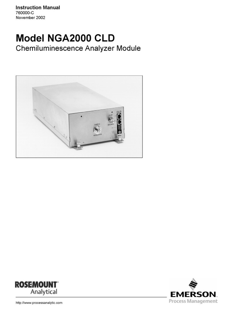
Emerson Numatics DeviceLogix G2-2 Series Instruction manual
Other Emerson Control Unit manuals
Emerson
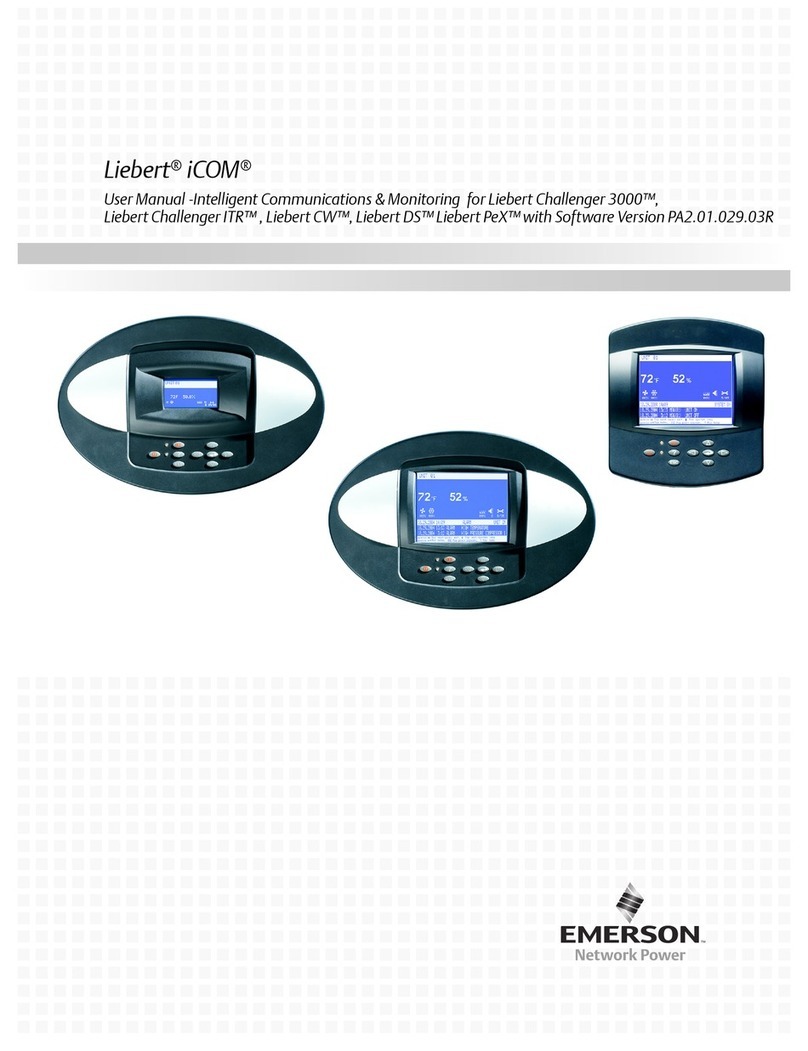
Emerson Liebert iCOM User manual

Emerson
Emerson White-Rodgers 36H Series User manual
Emerson
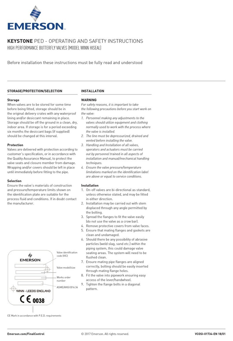
Emerson Keystone PED Winn Hiseal Quick guide
Emerson
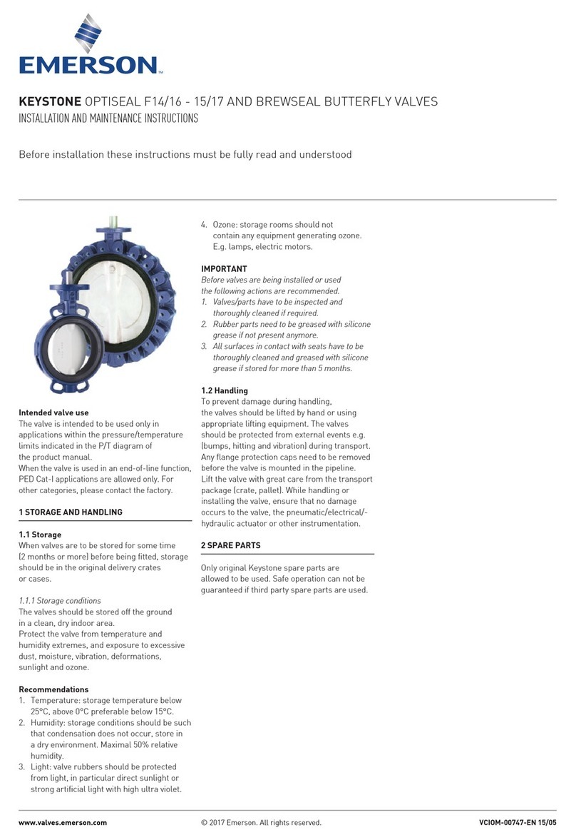
Emerson KEYSTONE OPTISEAL F16 User manual

Emerson
Emerson White-Rodgers 36C01 User manual

Emerson
Emerson Spence K3 User manual
Emerson
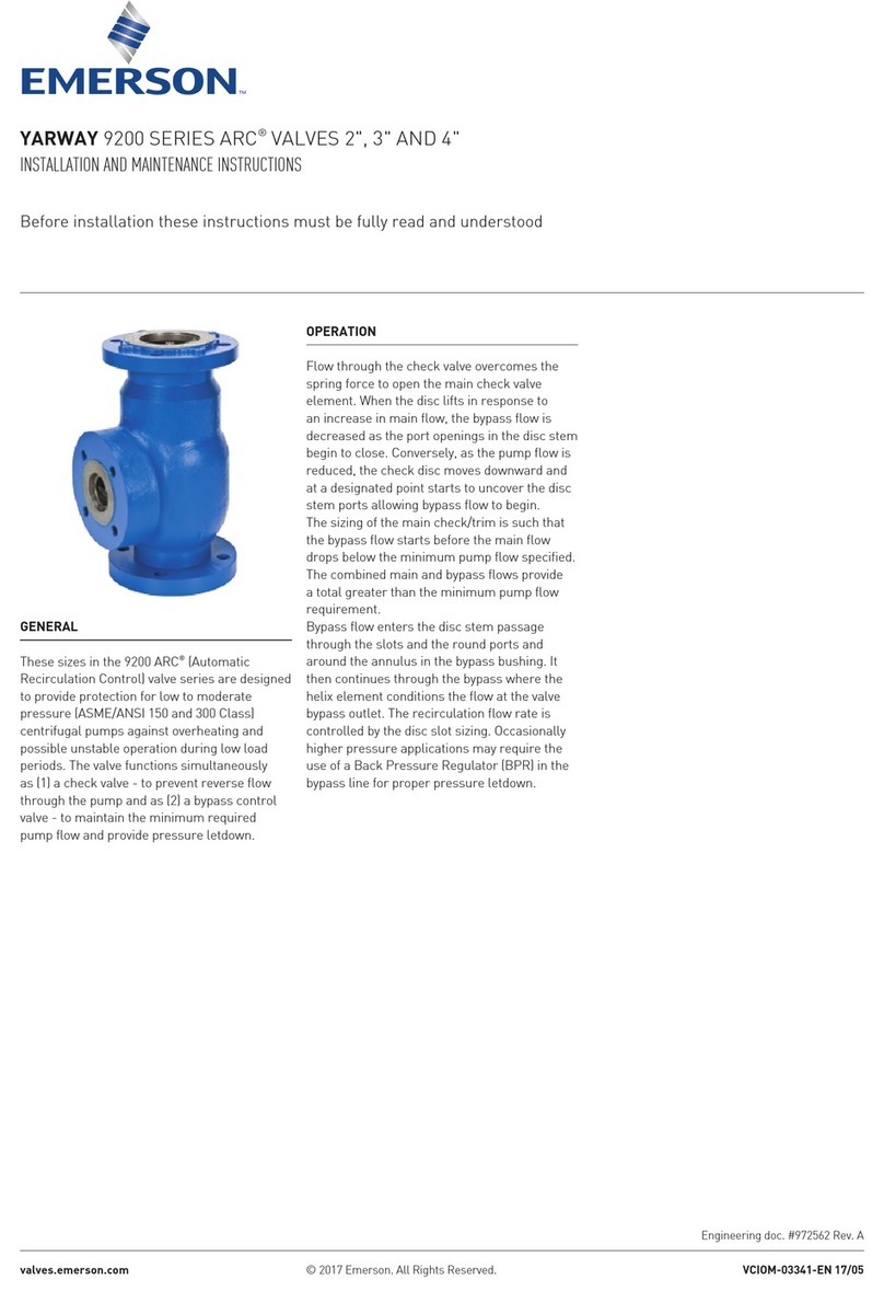
Emerson Yarway 9200 Series User manual
Emerson
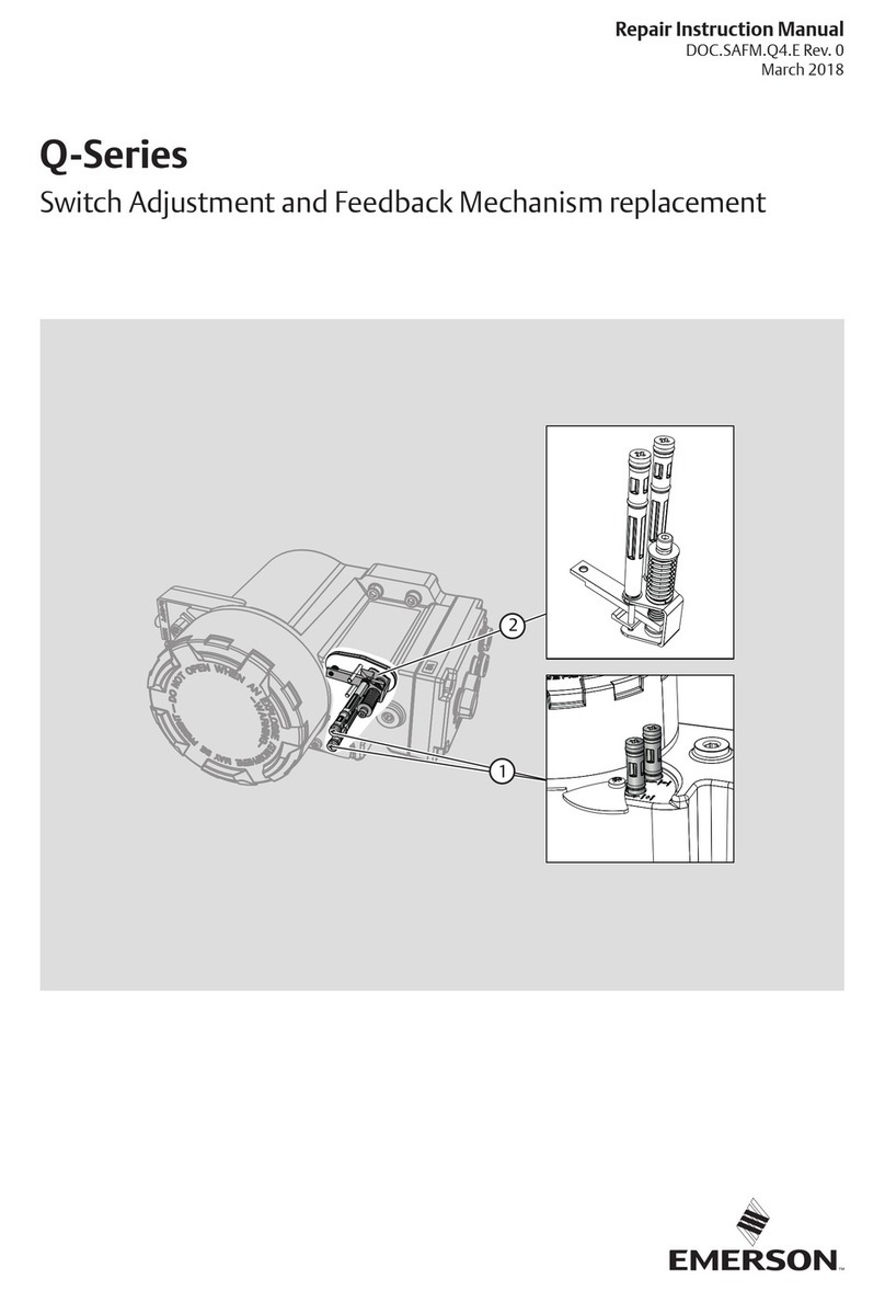
Emerson Q Series Setup guide

Emerson
Emerson PENBERTHY N6 Series Manual
Emerson
Emerson FRM-2 Manual
Emerson
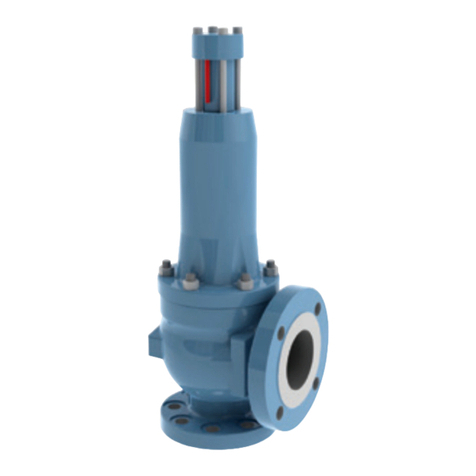
Emerson ASCO 290 Series User manual
Emerson
Emerson Sempell S Series User manual

Emerson
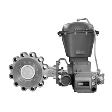
Emerson Fisher ET User manual
Emerson
Emerson Fisher A11 User manual

Emerson
Emerson 903 User manual
Emerson
Emerson SW95 User manual
Emerson
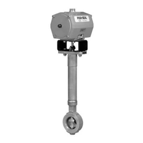
Emerson Fisher POSI-SEAL A31A User manual

Emerson
Emerson Fisher POSI-SEAL A31A User manual
Emerson
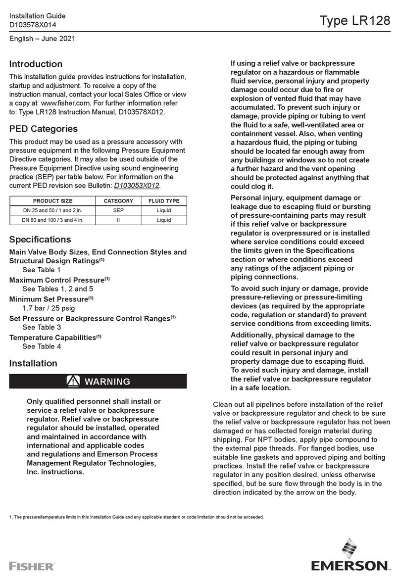
Emerson FISHER LR128 Series User manual

Emerson
Emerson Anderson Greenwood 95 Series User manual
Popular Control Unit manuals by other brands

Festo
Festo Compact Performance CP-FB6-E Brief description

Elo TouchSystems
Elo TouchSystems DMS-SA19P-EXTME Quick installation guide

JS Automation
JS Automation MPC3034A user manual

JAUDT
JAUDT SW GII 6406 Series Translation of the original operating instructions

Spektrum
Spektrum Air Module System manual

BOC Edwards
BOC Edwards Q Series instruction manual

KHADAS
KHADAS BT Magic quick start

Etherma
Etherma eNEXHO-IL Assembly and operating instructions

PMFoundations
PMFoundations Attenuverter Assembly guide

GEA
GEA VARIVENT Operating instruction

Walther Systemtechnik
Walther Systemtechnik VMS-05 Assembly instructions

Altronix
Altronix LINQ8PD Installation and programming manual
