HID iCLASS SE Instruction Manual

hidglobal.com
iCLASS SE Reader Module
Hardware Developer’s Guide
SE3200-902, Rev. C.1
February 2014

iCLASS SE Reader Module Hardware Developer’s Guide, SE3200-902, Rev. C.1
February 2014 Page 2 of 52
Contents
1Introduction........................................................................................................................... 7
1.1 Product Description ......................................................................................................................................7
1.1.1 Key Features.................................................................................................................................................................7
1.1.2 iCLASS SE Reader Module Products .................................................................................................................8
1.1.3 Product Guide..............................................................................................................................................................9
1.2 Scope/Purpose............................................................................................................................................... 9
1.3 Terms and Abbreviations..........................................................................................................................10
2Overview ................................................................................................................................11
2.1 Features.............................................................................................................................................................11
2.2 Block Diagram................................................................................................................................................12
2.3 Theory of Operation....................................................................................................................................13
2.3.1 Power Modes..............................................................................................................................................................13
2.3.2 Module – Transponder Interaction....................................................................................................................13
2.4 Peripheral Circuits........................................................................................................................................14
2.4.1 External Pull-up Resistors.....................................................................................................................................14
2.4.2 External Noise Filter................................................................................................................................................14
2.4.3 Adding External LEDs and Beeper...................................................................................................................14
2.5 Transitioning from the OEM50, OEM75 and eProxL Modules...................................................14
2.5.1 OEM50 ..........................................................................................................................................................................14
2.5.2 OEM75...........................................................................................................................................................................15
2.5.3 eProx Lock Module..................................................................................................................................................15
3Connector Configuration ..................................................................................................16
3.1 SE3200Axx Connectors ............................................................................................................................16
3.2 SE3210Axx Connectors..............................................................................................................................16
3.3 Pin Configuration..........................................................................................................................................17
3.3.1 P301 Host Interface Connector...........................................................................................................................17
3.3.2 P701 Power and I/O Connector..........................................................................................................................17
3.3.3 P702 Board to Board Connector.......................................................................................................................18
3.3.4 P401 HF Antenna Connector...............................................................................................................................19
3.3.5 E501/E502 Prox Antenna Connector ..............................................................................................................19
4Mechanical Specifications................................................................................................20
4.1 SE3200Axx ....................................................................................................................................................20
4.2 SE3210Axx.......................................................................................................................................................21
4.3 Connector Types .........................................................................................................................................22
4.3.1SE3210Axx Connector Types.............................................................................................................................22
4.3.2 SE3200Axx Interconnect.....................................................................................................................................22
5Electrical Specifications...................................................................................................23
5.1 Maximum Ratings........................................................................................................................................23
5.2 Current Draw.................................................................................................................................................23
5.3 Power Supply................................................................................................................................................24
5.4 Host Interfaces..............................................................................................................................................24
5.5 Wiegand ..........................................................................................................................................................24
5.6 I/O 25
5.7 Regulated Voltage Outputs....................................................................................................................25
5.8 RF Interface (13.56 MHz)..........................................................................................................................25
5.9 RF Interface (125 kHz/Prox) ...................................................................................................................26
5.10 Start Up Voltages........................................................................................................................................26

iCLASS SE Reader Module Hardware Developer’s Guide, SE3200-902, Rev. C.1
Page 3 of 52 February 2014
6RF Interfaces .......................................................................................................................27
6.1 HF Interface (13.56 MHz)..........................................................................................................................27
6.1.1 Ultra Low Power Mode .........................................................................................................................................29
6.2 Prox Interface (125 kHz; SE32x0APx only).......................................................................................30
7Antennas................................................................................................................................31
7.1 Basic Antenna Operation..........................................................................................................................31
7.1.1 Inductive Coupling..................................................................................................................................................32
7.1.2 Load Modulation......................................................................................................................................................33
7.2 Antenna Integration ...................................................................................................................................33
7.2.1 Steps to Integration................................................................................................................................................33
7.2.2 Antenna Interconnect Cable...............................................................................................................................33
7.2.3 Training and Assistance........................................................................................................................................33
7.3 4090A10 HF Antenna................................................................................................................................34
7.3.1 Mechanical Data.......................................................................................................................................................34
7.3.2 Typical Read Ranges with Standard Transponders .................................................................................34
7.3.3 Typical Read Ranges with HID Multi Technology Cards........................................................................36
7.3.4 ULPM Card Detection Range..............................................................................................................................36
7.3.5 RF Properties.............................................................................................................................................................37
7.3.6 Power Considerations ...........................................................................................................................................39
7.4 4090A11 HF Antenna................................................................................................................................ 40
7.4.1 Mechanical Data.......................................................................................................................................................40
7.4.2 Typical Read Ranges with Standard Transponders .................................................................................40
7.4.3 Typical Read Ranges with HID Multi Technology Cards........................................................................42
7.4.4 ULPM Card Detection Range..............................................................................................................................43
7.4.5 RF Properties.............................................................................................................................................................43
7.4.6 45
7.4.7 Power Considerations ...........................................................................................................................................46
7.5 6500-101-03 Prox Antenna .....................................................................................................................46
7.5.1 Mechanical Data.......................................................................................................................................................47
7.5.2 Electrical Characteristics......................................................................................................................................47
7.5.3 Typical Read Ranges..............................................................................................................................................48
8Regulatory............................................................................................................................49
8.1 RoHS .................................................................................................................................................................49
8.2 REACH..............................................................................................................................................................49
8.3 Safety – for Indoor Use Only ..................................................................................................................49
8.4 Product Radio Certifications ..................................................................................................................49
8.5 FCC 50
8.6 Canada Radio Certification .....................................................................................................................50
8.7 CE Marking .........................................................................................................................................................1

iCLASS SE Reader Module Hardware Developer’s Guide, SE3200-902, Rev. C.1
February 2014 Page 4 of 52
List of Figures
Figure 1: iCLASS SE Reader Module Block Diagram.......................................................................................................12
Figure 2: SE3200Axx Connector Configuration...............................................................................................................16
Figure 3: SE3210Axx Connector Configuration ................................................................................................................ 16
Figure 4: SE3200 Mechanical Drawing................................................................................................................................20
Figure 5: SE3210Axx Mechanical Drawing ...........................................................................................................................21
Figure 6: Output Circuit Wiegand Interface......................................................................................................................24
Figure 7: HF Interface...................................................................................................................................................................27
Figure 8: HF Interface with Coax Cable................................................................................................................................27
Figure 9: Basic Antenna Tuning Network........................................................................................................................... 28
Figure 10: Tuning Network with ULPM Support................................................................................................................29
Figure 11: iCLASS SE Reader Module Prox Interface with Antenna.........................................................................30
Figure 12: Inductive Coupling Principle................................................................................................................................. 32
Figure 13: Mutual Inductance between Reader and Transponder Antenna.......................................................... 32
Figure 14: Load Modulation Principle..................................................................................................................................... 33
Figure 15: 4090A10 HF Antenna..............................................................................................................................................34
Figure 16: 4090A11 HF Antenna ..............................................................................................................................................40
Figure 17: 6500-101-03 Prox Antenna....................................................................................................................................46
Figure 18: 6500-101-03 Mechanical Drawing......................................................................................................................47

iCLASS SE Reader Module Hardware Developer’s Guide, SE3200-902, Rev. C.1
Page 5 of 52 February 2014
List of Tables
Table 1: Feature Overview.........................................................................................................................................................11
Table 2: P301 Pin Configuration..............................................................................................................................................17
Table 3: P701 Pin Configuration..............................................................................................................................................17
Table 4: P702 Pin Configuration............................................................................................................................................ 18
Table 5: P401 Pin Configuration............................................................................................................................................. 19
Table 6: E501/E502 Pin Configuration................................................................................................................................19
Table 7: SE3210 Connector Types ........................................................................................................................................22
Table 8: Maximum Ratings ...................................................................................................................................................... 23
Table 9: Power Considerations.............................................................................................................................................. 23
Table 10: Power Supply Electrical Characteristics..........................................................................................................24
Table 11: Host Interface Electrical Characteristics..........................................................................................................24
Table 12: Wiegand Electrical Characteristics – Host Interface.................................................................................. 25
Table 13: I/O Electrical Characteristics – Host Interface.............................................................................................. 25
Table 14: Regulated Voltage Output Electrical Characteristics................................................................................ 25
Table 15: 13.56 MHz RF Interface - Electrical Characteristics Power Supply....................................................... 25
Table 16: 125 kHz RF Interface - Electrical Characteristics Power Supply............................................................ 26
Table 17: 4090A10 HF Antenna with Standard ID1 Transponders Read Ranges..............................................34
Table 18: Typical Read Ranges 4090A10 HF Antenna - HID Multi Technology Cards ...................................36
Table 19: ULPM Card Detection Ranges 4090A10 HF Antenna ............................................................................... 37
Table 20: ISO/IEC14443 Type A Modulation Waveforms ............................................................................................38
Table 21: ISO/IEC14443 Type B Modulation Waveforms.............................................................................................38
Table 22: FeliCa Waveforms.....................................................................................................................................................39
Table 23: Power Considerations..............................................................................................................................................39
Table 24: 4090A11 HF Antenna with Standard ID1 Transponders Read Ranges................................................40
Table 25: Typical Read Ranges 4090A11 HF Antenna - HID Multi Technology Cards.....................................42
Table 26: ULPM Card Detection Ranges 4090A10 HF Antenna ...............................................................................43
Table 27: ISO/IEC14443 Type A Modulation Waveforms ............................................................................................44
Table 28: ISO/IEC14443 Type B Modulation Waveforms.............................................................................................45
Table 29: FeliCa Waveforms.....................................................................................................................................................45
Table 30: Power Considerations..............................................................................................................................................46
Table 31: Electrical Characteristics 6500-101-03.............................................................................................................47
Table 32: Typical Read Ranges 6500-101-03 Prox Antenna.......................................................................................48

iCLASS SE Reader Module Hardware Developer’s Guide, SE3200-902, Rev. C.1
February 2014 Page 6 of 52
Copyright
©2014 HID Global Corporation/ASSA ABLOY AB.
All rights reserved. This document may not be reproduced, disseminated or
republished in any form without the prior written permission of HID Global
Corporation.
Trademarks
HID GLOBAL, HID, the HID logo, iCLASS, iCLASS SE, and SIO are the trademarks or
registered trademarks of HID Global Corporation, or its licensors, in the U.S. and other
countries.
MIFARE, MIFARE Classic, MIFARE DESFire, MIFARE DESFire EV1, MIFARE Plus, and
MIFARE Ultralight are registered trademarks of NXP B.V. and are used under license.
Revision History
Date
Author
Description
Version
February 2014 DJL Added section 5.10 Start Up Voltage C.1
September
2013 TS Update Voltage Input Rating in accordance to latest
UL certification C.0
Mar 2013 HP - Table 4: Changed pin 3 from NC to DNC
- Regulatory updates for FCC / IC compliance
- New copyright statement
- UL294 Certification
B.3
Feb 2013 HP Added 4090A11 HF antenna data B.2
Feb 2013 HP & LD Fixed formatting issues B.1
Oct 2012 HP & IRC Changed contacts for HID Connect
1.3 Product guide removed table & inserted ref to
micro-site
1.1.3 Remove product guide table
B.0
July 2012 H. Pirch Initial Version for internal Beta A
Contacts
North America
Europe, Middle East and Africa
15370 Barranca Parkway
Irvine, CA 92618
USA
Connect_Americas@HIDGlobal.com
Phoenix Road
Haverhill, Suffolk CB9 7AE
England
Connect_Europe@HIDGlobal.com
Asia Pacific
19/F 625 King’s Road
North Point, Island East
Hong Kong
Connect_APAC@HIDGlobal.com

iCLASS SE Reader Module Hardware Developer’s Guide, SE3200-902, Rev. C.1
Page 7 of 52 February 2014
1Introduction
1.1 Product Description
The iCLASS SE®Reader is part of HID Global’s next generation platform. The iCLASS
SE Reader goes beyond the traditional smart card model offering secure and
standards based independent technology and flexible identity data structure based on
Secure Identity Object™ (SIO®). SIO is a portable and open credential methodology.
Building on the success of the existing OEM modules (including the OEM50 and
OEM75) the iCLASS SE Reader enhances existing functionality with new SIO features.
The new features include supporting NFC smart phones and other devices for mobile
access while also providing increased levels of security.
The iCLASS SE Reader allows integrators to design third party solutions supporting a
full range of contactless card technologies, including iCLASS®, MIFARE®and HID Prox.
It also provides PIV II compliance/ FIPS 201 certification and appears on the GSA
Approved Products List (APL) allowing straightforward integration into U.S.
Government applications.
The iCLASS SE Reader’s dual frequency capability allows the use of both high and low
frequency credentials with the same reader, providing a solution for mixed credential
and credential migration applications.
Another key feature of the iCLASS SE Reader is the straightforward field upgrade
support that allows firmware changes and feature upgrades for installed readers to
extend the lifecycle of customer installations.
For quick and easy integration, HID Global also provides an iCLASS SE Reader
Developer Tool Kit (DTK). The DTK provides the necessary tools, documentation and
developer resources material to shorten integration cycles and speed time to market
with finished products.
1.1.1 Key Features
•Single platform supporting
§Secure Identity Object – Multi Layer security that extends beyond the card
technology, providing additional protection to identity data
§Dual Frequency and NFC Capability – Allows straightforward migration by
supporting low and high frequency credentials (including iCLASS, HID
Prox, Indala Prox, FeliCa™MIFARE Classic and MIFARE DESFireEV1) and
NFC enabled smart phones.
§Field upgradeability giving the installer the flexibility to implement new
features in the field and extending product lifecycle
•A complete flexible product line of reader boards, antennas and accessories.
•Developer tools and support. iCLASS SE Reader provides a fully featured
Development Tool Kit (DTK) providing web / desktop based tools and
documentation.
•Development support from HID Global Support Services
•Product pre-certification for industry standard bodies such as modular-FCC and
CE

iCLASS SE Reader Module Hardware Developer’s Guide, SE3200-902, Rev. C.1
February 2014 Page 8 of 52
•FIPS 201 PIV II compliance with inclusion on the GSA APL
•Ultra low power mode for battery- operated devices
•EAL5+ certified secure element hardware for protection of keys and
cryptographic operations to guard against security threats
1.1.2 iCLASS SE Reader Module Products
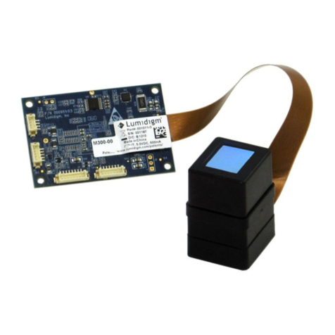
The iCLASS SE Reader Module comes in two form factors.
•3200 iCLASS SE Reader Module
Same form factor as OEM50
28mm x 30.5mm (1.10" x 1.20")
•3210 iCLASS SE Reader Module
Same form factor as eProx-Lock module
33mm x 43mm (1.3" x 1.7")
Development Tool Kit
•Development Board
•3200 and 3210 iCLASS SE Reader
Modules
•HF and LF Antennas and cables
•Sample Credentials
•Memory Stick containing development
tools and documentation

iCLASS SE Reader Module Hardware Developer’s Guide, SE3200-902, Rev. C.1
Page 9 of 52 February 2014
1.1.3 Product Guide
The iCLASS SE reader module comes in two form factors. It can also be configured for
high frequency card reading only or High & low frequency (prox).
In addition, there are two different levels of security provided.
Key Security Notes:
Standard V1 Security: Standard Security (Version 1) Keyset – coupled with the
Standard 13.56 MHz interpreter provides compatibility with iCLASS SE, iCLASS SR,
standard iCLASS, SE for MIFARE Classic and SE for MIFARE DESFire EV1 credentials.
Standard V2 Security: Standard Security (Version 2) Keyset – coupled with the SIO
(Only) 13.56 MHz interpreter provides compatibility with iCLASS SE, MIFARE Classic
SE and MIFARE DESFire EV1 SE credentials
Elite Security: Elite reads only SE Elite™ credentials with unique matching keys. Works
with iCLASS SE, iCLASS SR, standard iCLASS, SE for MIFARE Classic and SE for
MIFARE DESFire EV1 with matching Elite keys. Requires ICE reference number.
Prox Reading Notes:
Standard Prox: HID Prox, AWID, EM4102 and Indala (10022 – 26-bit)
Custom Prox: HID Prox, AWID, EM4102 and Indala Custom format
For full ordering information including options, see the Embedded Technology
Solutions How to Order Guide:
http://www.hidglobal.com/documents/embedded_htog_en.pdf.
1.2 Scope/Purpose
This document describes the hardware features of the iCLASS SE Reader Module. The
product is available in two form factors with various different configurations. Form
factor and host connectors are backward compatible to the OEM75 module.

iCLASS SE Reader Module Hardware Developer’s Guide, SE3200-902, Rev. C.1
February 2014 Page 10 of 52
1.3 Terms and Abbreviations
Abbreviation/Term
Description
ANT
Antenna
ARM
Advanced RISK Machine
CSN
Card Serial Number
DNC
Do Not Connect
EMC
Electro Magnetic Compatibility
FSK
Frequency Shift Keying
FCC
Federal Communication Commission
HF
High Frequency (13.56 MHz)
LED
Light Emitting Diode
NPM
Normal Power Mode
PICC
Proximity IC Card
FeliCa
Felicity Card
IC
Industry Canada (Industrie Canada)
I/O
Input / Output
LF
Low Frequency (125 kHz)
Optimized
Configured/Developed to operate at the best performance level
RF
Radio Frequency
RFID
Radio Frequency Identification
R&TTE
Radio and Telecommunications Terminal Equipment
SIO
Secure Identity Object
SPI
Serial Peripheral Interface
Ta
Ambient Temperature
TTL
Transistor – Transistor Logic
UART
Universal Asynchronous Receiver Transmitter
UID
Unique Identifier
UL
Underwriters Laboratories
USB
Universal Serial Bus
ULPM
Ultra Low Power Mode

iCLASS SE Reader Module Hardware Developer’s Guide, SE3200-902, Rev. C.1
Page 11 of 52 February 2014
2Overview
2.1 Features
Table 1: Feature Overview
Type
Feature
Comment
RF Interface
ISO/IEC14443 ISO/IEC14443 Type A&B up to 848kbps,
MIFARE Classic, MIFARE DESFire 0.6 & EV1
ISO/IEC15693 CSN only
Pico15693 ISO/IEC15693 with proprietary protocol
Pico14443B ISO/IEC14443 Type B with proprietary protocol
HID iCLASS ISO/IEC14443 and ISO/IEC15693 mode
FeliCa CSN only
HID Prox SE32x0APx only
Indala Prox
Host Interfaces
SPI
UART Suggested host interface
Wiegand Output only binary interface
Environmental
Properties
Operating
Temperature -25°C to 65°C
Storage Temperature -45°C to 85°C
Humidity 0-90% non condensing
Certifications
FCC & IC FCC and Industry Canada Modular Approval
CE Marking R&TTE Directive (Emissions, Indirect ESD, RF
Immunity)
RoHS & REACH
UL Recognized
Component UL 294
GSA SE32x0Axx-G3.0 only (in process)

iCLASS SE Reader Module Hardware Developer’s Guide, SE3200-902, Rev. C.1
February 2014 Page 12 of 52
2.2 Block Diagram
Figure 1: iCLASS SE Reader Module Block Diagram

iCLASS SE Reader Module Hardware Developer’s Guide, SE3200-902, Rev. C.1
Page 13 of 52 February 2014
2.3 Theory of Operation
2.3.1 Power Modes
•Normal Power Mode (NPM) – The module is constantly powered on and polling
for cards. The module is never asleep in this mode. Use this mode with an
external power supply. The module is always ready to receive a command from
the host.
•Ultra Low Power Mode (ULPM) – This power mode was designed for fixed
location battery powered applications (for example, door or cabinet lock). The
module is constantly monitoring the antenna for an impedance shift to detect a
card presented to the antenna. Once detecting an impedance shift on the HF
antenna, the module wakes up and polls for cards in the field. If a card is
detected in the RF field, the module reads the card data, pulses the Card Present
line, outputs the card data, and goes back to sleep within a configured period of
time to conserve power.
Note: If developing a handheld unit, operate the iCLASS SE Reader Module in
Normal Power Mode and disable the power when not in use.
Power
Autonomous Mode
Autonomous & API Mode
NPM üü
ULPM üafter autonomous output
2.3.2 Module – Transponder Interaction
Autonomous Mode – The iCLASS SE Reader Module is intended to automatically
access and report the secure payload or the serial number (UID/CSN) of a
transponder. Thereby it acts on its protocols and applications configuration to
automatically report the payload on its Wiegand, UART and/or SPI ports.
Advanced Protocol Interface Mode (API) – The host communicates with the
transponder in the field through the iCLASS SE Reader Module’s serial protocol.
(UART or SPI is required)
Note: API calls are available in ULPM after the module outputs its autonomous data
(configuration dependant).

iCLASS SE Reader Module Hardware Developer’s Guide, SE3200-902, Rev. C.1
February 2014 Page 14 of 52
2.4 Peripheral Circuits
The following section details recommended peripheral circuitry.
2.4.1 External Pull-up Resistors
External pull-up resistors may be required on the UART Tx and MOSI lines to prevent
floating I/O anomalies.
2.4.2 External Noise Filter
If false card detections occur in Ultra Low Power mode, or the host has spectral noise,
a line filter designed to block frequencies in the 10 KHz to 50 KHz range is beneficial
when inline with the power line.
2.4.3 Adding External LEDs and Beeper
The Cathodes are connected through an external resistor to the RED or GREEN LED
connector port signals. The OEM supplies current limiting resistors for modules.
The value of these resistors depends on how much current is provided for the LEDs.
Consider the combined voltage drop of the resistor and OEM75 output low voltage on
these signal lines when selecting the LED brightness.
2.5 Transitioning from the OEM50, OEM75 and eProxL Modules
Provided are suggestions for transitioning from the HID OEM50 and eProx Lock
modules to the OEM75.
2.5.1 OEM50
If you are transitioning from an OEM50 – here are the differences.
•The OEM50 connector is a 2 X 6 0.1" space pin header or PWB hole pattern.
•The OEM50 has a two-wire interface to the antenna and the iCLASS SE Reader
has a 2-wire interface for NPM and a 5-wire interface for ULPM applications.
Therefore, it is possible that the OEM50 antenna will work with the SIO
Processor Board in NPM.
•The harness and signal changes to adapt the signals from the OEM50 2 X 6
pattern to an OEM75 1 x 9 1.25mm pattern are the following.
Note: The additional P2 for HSI and SPI interfaces are 1 x 8 1.25mm pattern.
OEM50
SE32XX
P2 Connector
Pin 1 Exc Supply No signal on the SE32XX
Pin 2 Exc Return is
not used No signal on the SE32XX
Pin 3 Serial Transmit Same as P301 pin 8 - UART Transmit
Pin 4 Serial Receive Same as P301 pin 7 - UART Receive
Pin 5 Vdd Return Same as P701 pin 2 - Battery Minus
Pin 6 Vdd +5VDC Same as P701 pin 1 - Battery Positive
and 5VDC is a good supply voltage
P1 Connector

iCLASS SE Reader Module Hardware Developer’s Guide, SE3200-902, Rev. C.1
Page 15 of 52 February 2014
OEM50
SE32XX
Pin 1 Open Output SE32XX does not have a similar signal
Pin 2 Ground Same as P301 pin 2, signal Ground
Pin 3 Wiegand Data1
Wiegand data output is per the SIA AC-01 (1996.10)
specification, except Voh is 3.3VDC max, and not 4.0 to
5.5 VDC
OEM50 is inverted logic
Pin 4 Wiegand Data0
Wiegand data output is per the SIA AC-01 (1996.10)
specification, except Voh is 3.3VDC max, and not 4.0 to
5.5 VDC
OEM50 is inverted logic
Pin 5 Power On Reset Same as P701 pin 3 /Reset function
Pin 6 Hold Similar to P701 pin 4, however /Hold is low active
2.5.2 OEM75
The SE32XX module I/O is directly pin-for-pin compatible with the OEM75.
The OEM75 antennas are incompatible with the SE32XX module.
ULPM average current remains the same while peak current is higher for the SE32XX
module.
2.5.3 eProx Lock Module
The eProx®Lock connector is the same as the SE32XX connector P701.
CAUTION: The connections between the SE32XX and the eProx Lock modules are
reversed.
A straight-thru cable will not work. Twist the cable 180 degrees to ensure that Pin 1 on
one module correctly mates with Pin 1 on the other module.
The two-wire 125 kHz antenna for the eProx Lock may not be interchangeable with an
SE32XX Prox antenna.

iCLASS SE Reader Module Hardware Developer’s Guide, SE3200-902, Rev. C.1
February 2014 Page 16 of 52
3Connector Configuration
3.1 SE3200Axx Connectors
Figure 2: SE3200Axx Connector Configuration
3.2 SE3210Axx Connectors
Figure 3: SE3210Axx Connector Configuration

iCLASS SE Reader Module Hardware Developer’s Guide, SE3200-902, Rev. C.1
Page 17 of 52 February 2014
3.3 Pin Configuration
3.3.1 P301 Host Interface Connector
This connector is compatible with P1 of the OEM75 module.
Table 2: P301 Pin Configuration
Pin
Signal Name
Type
Function
1 +3.3 VDC Output 0.1W maximum power sourced output
2 GND Reference Logic level reference
3 SPI_CLK Input SPI clock signal
4 SPI_nCS Input SPI chip select (active low)
5 SPI_MOSI Input SPI data in
6 SPI_MISO Output SPI data out
7 URX Input UART data in
8 UTX Output UART data out
3.3.2 P701 Power and I/O Connector
This connector is compatible with P2 of the OEM75 module.
Table 3: P701 Pin Configuration
Pin
Signal Name
Type
Function
1 VIN Supply Supply Voltage Positive
2 VRTN Supply Supply Voltage Negative
3 nReset Input Reset (active low)
4 nHold Input
Signal that holds off the presentation of the
card data. When asserted, this line either
buffers a card or disables a card read until
released, as configured (active low)
5 nGLED_CPRES Output
The signal on this pin reflects the recognition
of a card near the antenna. The autonomous
read and buffered data from the credential is
output on the configured host interface.
6 WG_DATA0 Output Wiegand Data 0
7 WG_DATA1 Output Wiegand Data 1
8 nBEEPER Output Signal which enables off board signaling
9 nRLED Output Signal which can be used to enable an off
board LED

iCLASS SE Reader Module Hardware Developer’s Guide, SE3200-902, Rev. C.1
February 2014 Page 18 of 52
3.3.3 P702 Board to Board Connector
This connector is an alternative interconnection method to P301 and P701.
Table 4: P702 Pin Configuration
Pin
Signal Name
Type
Function
1 nHold Input
Signal that holds off the presentation of the
card data. When asserted, this line either
buffers a card or disables a card read until
released, as configured (active low).
2 VIN Supply Supply Voltage Positive
3 DNC Do Not Connect
4 VIN Supply Supply Voltage Positive
5 NC
6 VRTN Supply Supply Voltage Negative
7 URX Input UART data in
8 SPI_MISO Output SPI data out
9 UTX Output UART data out
10 SPI_MOSI Input SPI data in
11 WG_DATA1 Output Wiegand Data 1
12 VRTN Supply Supply Voltage Negative
13 WG_DATA0 Output Wiegand Data 0
14 DNC Do Not Connect
15 DNC Do Not Connect
16 DNC Do Not Connect
17 DNC Do Not Connect
18 nReset Input Reset (active low)
19 +3.3VDC Output 0.1W maximum power sourced output
20 VRTN Supply Supply Voltage Negative
21 nGLED_CPRES Output
The signal on this pin reflects the recognition
of a card near the antenna. The autonomous
read and buffered data from the credential is
output on the configured host interface.
22 SPI_CLK Input SPI clock signal
23 nBeeper Output Signal which enables off board signaling
24 SPI_nCS Input SPI chip select (active low)
25 NC Not Connected
26 VRTN Supply Supply Voltage Negative
27 DNC Do Not Connect
28 nRLED Output Use this signal to enable an off board LED
29 DNC Do Not Connect
30 NC Not Connected

iCLASS SE Reader Module Hardware Developer’s Guide, SE3200-902, Rev. C.1
Page 19 of 52 February 2014
3.3.4 P401 HF Antenna Connector
This antenna connection IS NOT compatible with an OEM75 antenna.
Table 5: P401 Pin Configuration
Pin
Signal Name
Type
Function
1 ATX Output 13.56 MHz antenna driving signal
2 GND Reference Antenna ground reference
3 PING_LVL Input Signals for low power card detection in ULPM
4 PING_SIG Output
5 PING_EN Output
3.3.5 E501/E502 Prox Antenna Connector
Table 6: E501/E502 Pin Configuration
Pin
Signal Name
Type
Function
E501 PROX_TX1 Output 125 kHz antenna driving signal
E502 PROX_TX2 Output

iCLASS SE Reader Module Hardware Developer’s Guide, SE3200-902, Rev. C.1
February 2014 Page 20 of 52
4Mechanical Specifications
The following section details the mechanical specifications for the iCLASS SE Reader
Module and its connectors. Detailed drawings are also available at the iCLASS SE
Reader Module micro-site.
4.1 SE3200Axx
This form factor is compatible with OEM75 model 3141ADx.
Figure 4: SE3200 Mechanical Drawing
Other manuals for iCLASS SE
2
Table of contents
Other HID Control Unit manuals
Popular Control Unit manuals by other brands
CALEFFI
CALEFFI 146 Series Installation and commissioning manual
Alutech
Alutech A-box/ADS Installation and operation manual

Samson
Samson 3251 Mounting and operating instructions

Beninca
Beninca DA.2XS433 operating instructions
tedee
tedee BleBox smart installation manual

Sanken
Sanken SLA7070MMPR Series Application Information
