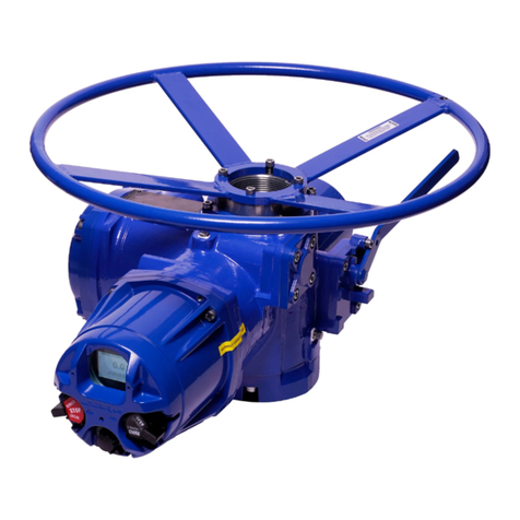
Flowserve FLEX 6300 Installation instructions

These instructions must be read prior to installing, operating, and
maintaining this equipment.
Flowserve FLEX™
Installation
Operation
Maintenance
Isobaric Energy Recovery Device
21TEM14546 EN
Original Instructions

FLEX User Instruction –21TEM14546 EN
Copyright
All rights reserved. No part of these instructions may be reproduced, stored in a retrieval
system, or transmitted in any form or by any means without prior permission of Flowserve
Corporation.
Document Version
Initial Release, 07-DEC-2021

FLEX User Instruction –21TEM14546 EN
Page 2of 43
CONTENTS
1General Information........................................................................................................................4
1.1 Scope of manual..........................................................................................................................................4
1.2 Disclaimer ......................................................................................................................................................4
1.3 Certification instruction................................................................................................................................5
1.4 Units ................................................................................................................................................................5
2Safety Information ...........................................................................................................................6
2.1 Intended use.................................................................................................................................................6
2.2 Safety symbols and description..................................................................................................................6
2.3 General hazard sources ..............................................................................................................................7
2.4 Responsibility of the operating company .................................................................................................8
2.5 Qualified personnel and targeted group .................................................................................................8
2.6 Industrial health and safety measures .......................................................................................................9
2.7 Protective equipment..................................................................................................................................9
3Product Description.......................................................................................................................10
3.1 General product description ................................................................................................................... 10
3.2 FLEX design................................................................................................................................................. 11
3.3 Function in an RO system ......................................................................................................................... 12
3.4 System design ............................................................................................................................................ 12
3.5 Header design ........................................................................................................................................... 13
3.6 Connections............................................................................................................................................... 16
3.7 Accessories................................................................................................................................................. 16
4Packaging, Lifting and Storage ...................................................................................................17
4.1 Consignment receipt................................................................................................................................ 17
4.2 Unpacking.................................................................................................................................................. 17
4.3 Packaging.................................................................................................................................................. 18
4.4 Lifting........................................................................................................................................................... 20
4.5 Storage ....................................................................................................................................................... 20
5Installation ......................................................................................................................................21
5.1 Inspection and preparation..................................................................................................................... 21
5.2 Mounting and installation......................................................................................................................... 22
6Operation .......................................................................................................................................24
6.1 Commissioning........................................................................................................................................... 24
6.2 Start-up ....................................................................................................................................................... 24
6.3 Normal operation ...................................................................................................................................... 25
6.4 Shut down .................................................................................................................................................. 26
7Maintenance .................................................................................................................................28
7.1 Maintenance procedure ......................................................................................................................... 28
7.2 Cleanliness ................................................................................................................................................. 28
7.3 Tools, equipment, and fixtures ................................................................................................................. 29

FLEX User Instruction –21TEM14546 EN
Page 3of 43
7.4 Torque requirements ................................................................................................................................. 29
7.5 Disassembly ................................................................................................................................................ 29
7.6 Reassembly ................................................................................................................................................ 30
7.7 Post-maintenance inspection.................................................................................................................. 31
7.8 Spare parts ................................................................................................................................................. 31
8Troubleshooting Guide .................................................................................................................33
9Decommissioning and Recommissioning ..................................................................................34
9.1 Decommissioning ...................................................................................................................................... 34
9.2 Recommissioning....................................................................................................................................... 34
10 Returns and Disposal.....................................................................................................................35
10.1 Returns ........................................................................................................................................................ 35
10.2 Disposal and recycling ............................................................................................................................. 35
11 Technical Data...............................................................................................................................36
11.1 Equipment dimensions and weights ....................................................................................................... 36
11.2 Nameplate................................................................................................................................................. 36
11.3 Operating limits.......................................................................................................................................... 36
11.4 Noise level .................................................................................................................................................. 37
Annex A: Declaration of Conformity ..................................................................................................38
Annex B: Supplementary User Instructions ........................................................................................39

FLEX User Instruction –21TEM14546 EN
Page 4of 43
1General Information
1.1 Scope of manual
These instructions must be kept close to the product’s operating location or directly with
the product.
These instructions must be read prior to installing, operating, using, or maintaining the
equipment in any region worldwide. The equipment must not be put into service until all of the
safe operating conditions noted in the instructions have been met. Failure to comply with the
information provided in the User Instructions is considered to be misuse. Personal injury, product
damage, delay in operation, or product failure caused by misuse are not covered by the
Flowserve warranty.
The following user information covers the Flowserve FLEX™ 6300 and 8600.
These instructions are intended to familiarize the reader with the product and its permitted use.
Operating the product in compliance with these instructions is important to help ensure reliability
in service and avoid risks. These instructions may not take into account all local regulations;
ensure such regulations are observed by all, including those installing the product. Always
coordinate repair activities with operations personnel and follow all plant safety requirements
and applicable safety and health legislation.
Supplementary user instructions determined from the contract requirements for inclusion into
User Instructions for buy-out equipment such as instrumentation, controller, coupling, mounting
component, etc. are included in Annex B: Supplementary User Instructions.
The typical general arrangement drawing, and any specific drawings required by the contract
will be sent to the Purchaser separately unless the contract specifically calls for these to be
included into the User Instructions. If required, copies of other drawings sent separately to the
Purchaser should be obtained from the Purchaser and retained with these User Instructions.
1.2 Disclaimer
Information in this User Instruction is believed to be complete and reliable. In spite of all
Flowserve’s efforts to provide comprehensive information and instructions, sound engineering
and safety practices should always be used. Please consult with a qualified engineer.
Flowserve manufactures products to applicable International Quality Management System
Standards as certified and audited by external Quality Assurance organizations. Genuine parts
and accessories have been designed, tested, and incorporated into the products to help
ensure continued product quality and performance in use. As Flowserve cannot test parts and
accessories sourced from other vendors, the incorrect incorporation of such parts and
accessories may adversely affect the performance and safety features of the product. The
failure to properly select, install, or use authorized Flowserve parts and accessories is considered
to be misuse. Damage or failure caused by misuse is not covered by Flowserve’s warranty. In
addition, any modification of Flowserve products or removal of original components may impair
the safety of these products in use.

FLEX User Instruction –21TEM14546 EN
Page 5of 43
1.3 Certification instruction
It is a legal requirement that machinery and equipment put into service within certain regions of
the world shall conform to the Marking Directives applicable to Flowserve products (i.e.,
Machinery Directive, Low Voltage Directive, Electromagnetic Compatibility (EMC) Directive,
Pressure Equipment Directive (PED), Equipment for Potentially Explosive Atmospheres (ATEX),
etc.).
Certificates defined in the Contract requirements are provided with these instructions where
applicable. Examples of the certificates can be found in the Annex of this document. If required,
copies of other certificates sent separately to the Purchaser should be obtained from the
Purchaser for retention with this User Instruction.
1.4 Units
This document uses dual ISO and US units.

FLEX User Instruction –21TEM14546 EN
Page 6of 43
2Safety Information
2.1 Intended use
The product/system must not be operated beyond the parameters specified for the
application. If there is any doubt as to the suitability of the product/system for the application
intended, contact Flowserve for advice, quoting the serial number.
•Installing, operating, or maintaining the product/system in any way that is not covered in
this User Instruction could cause death, serious personal injury, or damage to the
equipment. This includes any modification to the product/system or use of parts not
provided by Flowserve.
•Only operate the product/system when it has successfully passed all inspection
acceptance criteria.
•Do not operate the product/system in a partially assembled condition.
•If the conditions of service on the customer’s purchase order change (i.e., pumping fluid,
temperature, or duty conditions) it is requested that the user seeks written agreement
from Flowserve before startup.
•Observe equipment labels, such as arrows designating the direction of flow, warning
signs, etc., and keep them in a legible condition. Replace any damaged and/or illegible
labels immediately.
2.2 Safety symbols and description
This User Instruction contains specific safety markings where non-observance of an instruction
would cause a hazard. The specific safety markings can be found in Table 1 and Table 2.
Table 1: Definition of safety symbols and markings
SYMBOL
DESCRIPTION
DANGER
This symbol indicates a hazardous situation which, if not
avoided, will result in death or serious injury
WARNING
This symbol indicates a hazardous situation which, if not
avoided, could result in death or serious injury
CAUTION
This symbol indicates a hazardous situation which, if not
avoided, could result in minor or moderate injury
SAFETY INSTRUCTION
This symbol indicates specific safety-related instruction or
procedures
NOTICE
This symbol is used to address practices not related to
physical injury

FLEX User Instruction –21TEM14546 EN
Page 7of 43
SYMBOL
DESCRIPTION
This is the safety alert symbol. It is used to alert you to
potential physical injury hazards. Obey all safety messages
that follow this symbol to avoid possible injury or death
Table 2: Additional symbols
SYMBOL
DESCRIPTION
ELECTRICAL HAZARD
This symbol indicates electrical safety instructions where non-compliance
would affect personal safety and could result in loss of life
TOXIC HAZARD
This symbol indicates “hazardous substances and toxic fluid” safety
instructions where non-compliance would affect personal safety and
would damage the equipment or property
ATEX EXPLOSION PROTECTION
This symbol indicates explosive atmosphere marking according to ATEX.
It is used in safety instructions where non-compliance in the hazardous
area would cause the risk of an explosion
2.3 General hazard sources
This is a summary of conditions and actions to help prevent injury to personnel and damage to
the environment and to equipment.
2.3.1 Mechanical Hazards
Lifting limits and guidelines
Note: The load values mentioned in this section are Flowserve recommendations only. All lifting
must be done in compliance with site safety protocol, local regulations, and related industry
standards.
Many precision parts have sharp corners which require appropriate personal protective
equipment during handling. Prior to any attempt to lift an item, employees must first determine
the approximate weight and stability of the load.
•Large, unstable, or awkward loads should always be handled with the assistance of
additional personnel or appropriate mechanical means.
•Loads in excess of 23 kg (50 lb) should only be lifted by appropriate mechanical means
and in accordance with current local legislation or with the assistance of additional
personnel.
•Lifting items less than 23 kg (50 lb) may be prohibited without assistance if the lift is
repetitive and/or awkward (i.e., away from the body, above the shoulders or below the
knees) thus placing excessive stress on the personnel.

FLEX User Instruction –21TEM14546 EN
Page 8of 43
•Repetitive lifting of any kind should be evaluated as part of a documented end-user
safety program.
2.3.2 Additional hazards
DRAIN AND ISOLATE PIPEWORK BEFORE DISMANTLING
Residual high-pressure can remain in the FLEX units depending on how the system is shut down.
Ensure the FLEX units have been isolated from the system and relieved of all pressure before
dismantling any connections on the device.
PREVENT EXCESSIVE EXTERNAL PIPE LOAD
Refer to documentation from pipe coupling OEM for recommendations on system design,
operating limits, and allowable nozzle loads. It is not recommended to use pipe couplings to
support the static or dynamic loads of the FLEX unit(s).
NEVER EXCEED THE MAXIMUM DESIGN PRESSURE
ENSURE SYSTEM IS PROPERLY GROUNDED
The FLEX vessels make direct metal-to-metal contact with high-pressure system piping through
the pipe coupling connections. No specific grounding connection for the FLEX is required as
long as the high-pressure system piping is grounded.
2.4 Responsibility of the operating company
To ensure personnel safety, the operating company shall:
•Complete a risk assessment of the site where the product/system will be in operation, by
observing the working conditions
•Create site specific work instructions for the operation of the product
•Ensure that the personnel have read and understand all applicable instructions
•Provide regular training to the necessary personnel in regular intervals
•Provide the required personal protective equipment
2.5 Qualified personnel and targeted group
All personnel involved in the operation, installation and maintenance of the unit must be
qualified to carry out the work involved. If the personnel in question does not already possess the
necessary knowledge and skill, appropriate training and instruction must be provided. If
required, the operator may commission the manufacturer/supplier to provide applicable
training.
Always coordinate repair activities with operation and health and safety personnel and follow all
plant safety requirements and applicable safety and health laws and regulations.

FLEX User Instruction –21TEM14546 EN
Page 9of 43
2.6 Industrial health and safety measures
Follow industry safety standards including the use of appropriate equipment in required areas.
2.7 Protective equipment
Necessary protective equipment including personal protective equipment shall adhere to
facility standards.

FLEX User Instruction –21TEM14546 EN
Page 10 of 43
3Product Description
3.1 General product description
Figure 1: Isometric view of the Flowserve FLEX™
The Flowserve FLEX™ is an isobaric energy recovery device designed for reverse osmosis
seawater desalination applications. It takes the energy of a high-pressure fluid waste stream
and transfers the pressure energy to a low-pressure fluid supply stream. The simple design does
not require any external power, has only one moving part, and uses corrosion-proof materials for
high reliability and long life.

FLEX User Instruction –21TEM14546 EN
Page 11 of 43
3.2 FLEX design
The following sections describe the functions of the primary components in the FLEX. For further
clarity, refer to Figure 1 and Figure 12 (page 30) for isometric and exploded views of the device.
3.2.1 Vessel
The vessel acts as the primary pressure containment boundary for the device and contains
passageways (called ports or nozzles) that direct flow between external pipe connections and
appropriate end cover ports inside the device. The center flange allows the vessel to split in two
for access to the internal ceramic cartridge during maintenance.
3.2.2 Accessories
There are two bosses on the outside of the vessel for auxiliary equipment. One boss is fitted with
a sight-glass that allows direct observation of rotor speed using an optical tachometer to
confirm proper operation of the unit. The other boss is machined to allow mounting of an
accelerometer or other customer instrumentation.
3.2.3 End cover
The end covers on either side of the ceramic cartridge direct flow between the vessel ports and
rotor ducts. Low-pressure flow is directed through the end cover in a way that drives the rotation
of the rotor. The end covers also control pressure distribution around the cartridge to reduce
pressure forces and control leakage.
3.2.4 Rotor
The rotor provides a series of ducts that flow back and forth as it rotates to exchange pressure
between the high-pressure waste and low-pressure feed fluid streams. The rotor is designed to
minimize the region inside the ducts where the two fluid streams mix, as well as handle the cyclic
loading between high and low pressure as it spins.
3.2.5 Axle
The axle provides a bearing surface to support and center the rotor. Having this bearing surface
on the inner diameter of the rotor minimizes the amount of lubrication flow that must leak
through the bearing clearances.
3.2.6 Materials
All components that are wetted by the process fluid are made of titanium, alumina ceramic,
non-metallic, and composites that will not corrode in seawater and brine. External bolting is
made of duplex stainless steel to minimize corrosion in a salt air environment. Non-metallic and
composite materials that contact the process fluid are compatible with potable water
applications.

FLEX User Instruction –21TEM14546 EN
Page 12 of 43
3.3 Function in an RO system
The Flowserve FLEX™ is an isobaric energy recovery device designed for reverse osmosis (RO)
seawater desalination applications. It takes the energy of a high-pressure fluid waste stream
and transfers the pressure energy to a low-pressure fluid supply stream. The simple design does
not require any external power, has only one moving part, and uses corrosion-proof materials for
high reliability and long life.
In an RO desalination application like the one shown in Figure 2, the high-pressure waste stream
entering the FLEX is brine leaving the membrane filters. The energy from this brine is transferred
to low-pressure seawater provided to the FLEX from the system’s low-pressure feed pump.
Seawater then leaves the FLEX at nearly the same pressure as the incoming brine. A small
booster pump is used to overcome piping friction losses between the brine outlet of the
membrane and the point that this seawater will be injected back into the membrane inlet. The
final outlet of the FLEX unit is the brine reject leaving at low-pressure. A control valve is used at
this location to maintain a minimum backpressure on the device.
Figure 2: Process flow diagram for a typical FLEX system
There are three sources of energy loss through the FLEX device: hydraulic, volumetric, and
mixing. Hydraulic loss occurs due to friction loss of fluid flowing through the device and
providing energy to drive rotation of the rotor. This is measured as a pressure differential from
inlet to outlet of the device on both the high-pressure and low-pressure sides. Volumetric loss is
caused by fluid leaking from high-pressure to low-pressure inside the device, providing
lubrication and cooling to the bearing surfaces. Mixing loss occurs due to turbulence at the
interface between brine and seawater inside the rotor ducts, and results in a small increase in
salinity of the seawater as it flows through the FLEX from low-pressure inlet to high-pressure outlet.
3.4 System design
A backpressure control valve must be included in the low-pressure brine discharge line. The
valve should be appropriately sized and selected to allow throttling of the flow to maintain
backpressure at or above the minimum level required by the FLEX. Maintaining backpressure at
or above the minimum required level will reduce cavitation and prolong life of FLEX unit(s).

FLEX User Instruction –21TEM14546 EN
Page 13 of 43
Filtration of the process fluid must occur upstream of the FLEX device to avoid damaging the unit
and the precision clearances inside of it. Filters should have a maximum particle size of 20 μm
(0.8 mils) or smaller.
A circulation pump (or booster pump) is required on the high-pressure side of FLEX system piping.
This pump is used to overcome system resistance as process fluid flows from the membrane
outlet, through the FLEX, and back to the high-pressure feedwater inlet of the membranes. This
pump should be installed with either a variable speed drive or a throttling valve to control high
pressure flow rate through the FLEX.
Pressure relief devices should be provided on system piping to prevent over pressurization of
either the FLEX device or low-pressure system piping. Over pressurization may create a hazard
for personnel or result in damage to the FLEX device. It is recommended to install appropriately
sized and rated pressure relief devices on the high-pressure and low-pressure inlets to the FLEX.
Flushing lines should be connected to the system in a way that allow independent flushing of the
high-pressure and low-pressure system piping around the FLEX device.
Vent connections should be placed to ensure that system piping and FLEX units can be
completely flooded, and all air can be purged from the system before startup.
Isolation valves and drain lines should be appropriately placed in system piping to allow isolation
of the FLEX units(s) from the system for safe inspection and maintenance.
3.5 Header design
Headers can be used to place multiple FLEX units in parallel and achieve higher total system
flow than would be possible with any single unit. Care should be taken in designing the header
system to ensure that an even flow distribution between FLEX units is achieved. An uneven flow
distribution can result in excessive mixing and unreliable operation.
Figure 3: U-flow configuration
Figure 4: Z-flow configuration
Two flow configurations can be used to design the headers for a rack of FLEX units: U-flow and Z-
flow configurations. U-flow has flow that enters and leaves on the same side of the rack. Z-flow
has flow that enters on one side of the rack and leaves on the other size. Examples of these
configurations are shown in Figure 3 and Figure 4.

FLEX User Instruction –21TEM14546 EN
Page 14 of 43
An analysis of the total system resistance from header inlet to header outlet provides some
important guidelines on how to design headers to achieve an even flow distribution between
FLEX units operating in parallel with each other:
1. Maintaining low header flow velocity is more important than which configuration is
chosen. Lower header flow velocity will result in more even flow distribution between
FLEX units, but as a general guideline header flow velocity should be maintained below 3
m/s (10 ft/s).
2. A Z-flow configuration provides more even flow distribution between FLEX units than a U-
flow configuration.
3. A Z-flow configuration can have high-pressure and low-pressure flow enter and exit on
either side of the rack and maintain the same flow distribution between units in the rack;
however, a U-flow header should have high-pressure and low-pressure flow enter and
exit on the same side of the rack so that any uneven flow distributions are equal on the
high-pressure and low-pressure sides, and the flow balance for each individual unit will
remain equal. Guidelines for acceptable header configurations are shown in Figure 5.
Figure 5: Acceptable header flow configurations
Mounting orientation is important for the design of mounting fixtures and system piping but does
not affect operation of the FLEX. FLEX units can be mounted in any orientation in the headers:
horizontal, vertical with brine on top, or vertical with brine on bottom.

FLEX User Instruction –21TEM14546 EN
Page 15 of 43
Adapter pipes should be placed between the headers and FLEX units to provide a more robust
and forgiving connection than can be achieved by simply coupling the FLEX units directly to the
headers. The adapters should have grooved pipe connections on both ends and use flexible
split style couplings on both the header and FLEX connections. Refer to documentation from the
pipe coupling OEM for further guidance on proper piping design.
Material selection is important for both the high-pressure and low-pressure headers and adapter
pipes. High-pressure headers and piping are typically made of duplex or super duplex stainless
steel because of its corrosion resistance and strength. For the low-pressure headers and piping,
Flowserve recommends the use of Polyethylene (PE) or Polypropylene (PP) rather than
Polyvinylchloride (PVC) wherever possible.

FLEX User Instruction –21TEM14546 EN
Page 16 of 43
3.6 Connections
3.6.1 Piping connections
Each FLEX unit has four pipe end connections with grooved ends for split couplings:
•FLEX 6300 3-inch NPS pipe Grooved pipe end (to Victaulic OGS specifications)
•FLEX 8600 4-inch NPS pipe Grooved pipe end (to Victaulic OGS specifications)
REMOVE PROTECTIVE COVERS FROM NOZZLES PRIOR TO INSTALLATION
Protective covers are fitted to all pipe connections on the device to prevent foreign objects and
debris from contaminating the device. Covers should remain in place until the unit is ready to
install. These covers must be removed prior to connecting the unit to any pipes.
USE APPROPRIATELY RATED COUPLINGS ON HIGH-PRESSURE CONNECTIONS
Pipe couplings with pressure ratings above the highest expected system pressure must be used
on high-pressure connections to the device.
PREVENT EXCESSIVE EXTERNAL PIPE LOAD
Refer to documentation from pipe coupling OEM for recommendations on system design,
operating limits, and allowable nozzle loads. It is not recommended to use pipe couplings to
support the static or dynamic loads of the FLEX unit(s).
3.6.2 Auxiliary connections
A ¼”-24 UNF threaded connection on the vessel can be used to attach an accelerometer or
other auxiliary instrumentation.
3.7 Accessories
No accessories are required to operate the device. Optional accessories include an optical
tachometer and an accelerometer to confirm proper operation and flow balance between
units in a rack and to monitor the device for issues over time.

FLEX User Instruction –21TEM14546 EN
Page 17 of 43
4Packaging, Lifting and Storage
4.1 Consignment receipt
Immediately after receipt of the products, customer should verify that the goods received
exactly match the delivery/shipping documents, and that there has been no damage in
transportation. Any shortage or damage must be reported immediately to Flowserve and must
be received in writing within one month of receipt of the goods. Later claims cannot be
accepted.
The following symbols are used to label the packaging:
This side up Fragile
Keep dry Protect from direct sunlight
Center of gravity Do not use hooks
Attachment point
4.2 Unpacking
The FLEX and its associated equipment are carefully inspected at the factory prior to shipment to
ensure quality compliance. Customer should visually inspect the goods on arrival and report
any irregularities or damage to the carrier immediately.
The condition of the skid and covering is indicative of the way the shipment was handled.
Broken skids, torn covering, bent hold-down bolts, broken straps, etc., indicate rough handling.
The protective covers on the FLEX nozzles should be in place and undamaged.
Take care when removing crating, coverings, and strapping in order not to damage any
equipment and/or the FLEX’s finish.
Inspect all crates, boxes, or wrappings for any accessories or spare parts that may be packed
separately with the equipment or attached to the side wall of the box or equipment.
Each FLEX has a unique serial number. Check that this number corresponds with that advised
and always refer to this number in correspondence as well as when ordering spare parts or
further accessories.

FLEX User Instruction –21TEM14546 EN
Page 18 of 43
4.3 Packaging
4.3.1 General FLEX packaging guidelines
It is the responsibility of the Facility to ensure packaged items are in a suitable container or
transporting device that protects the items from exterior forces, impact, vibration, and
environmental conditions. Before packaging items, ensure the following:
1. Inspect all items for cleanliness immediately before packaging. Dirt, oil residue, metal
chips, or other forms of contamination shall be removed by approved cleaning methods.
2. Components which are not immediately packaged must be protected from
contamination. Use nozzle covers to prevent foreign objects and debris from entering
the device. Package with a barrier to prevent water vapor, salt air, dust, dirt, and other
forms of contamination from penetrating the package.
3. Items and their containers shall be properly identified by markings.
Before shipping, prepare a packing slip and fasten it to the unit. The packaging slip shall contain
the following information:
1. Customer’s purchase order number
2. Flowserve job number
3. Customer’s name and address
4. “Ship to” address
5. Quantity
6. Description
7. Date shipped
8. Carrier used
For shipments with more than one unit container or package for any given order, each parcel
shall be properly marked (such as 1 of 3, 2 of 3, etc.) and contain a copy of the packing list.
4.3.2 Typical Flowserve packaging
FLEX units shipped from a Flowserve facility will typically be packaged in the following manner:
(see the pictures in Figure 6 through Figure 10 for examples)
•Protective covers will be fitted to each of the four nozzles to prevent internal
contamination.
•Individual containers will be used to package each unit.
•Protective padding will be fitted in each container to prevent external forces, impact, or
vibration during transport from damaging the device.
•Appropriate labels will be fastened externally to each container.
•Multiple containers will be appropriately stacked and fastened together on a pallet.

FLEX User Instruction –21TEM14546 EN
Page 19 of 43
Figure 6: Multiple containers on a pallet
Figure 7: Single FLEX container
Figure 8: Top of protective padding
Figure 9: Top protective padding removed
Figure 10: FLEX unit with nozzle covers
This manual suits for next models
1
Table of contents
Other Flowserve Plumbing Product manuals
Popular Plumbing Product manuals by other brands

Häfele
Häfele HT21-CH1F220C instruction manual

DURAVIT
DURAVIT DuraStyle 1004180000 Service instructions

Miomare
Miomare HG03546A Assembly, operating and safety instructions

IKEA
IKEA ENSEN Assembly instructions

Hans Grohe
Hans Grohe Punto manual

Teuco
Teuco Milestone Assembly Instructions - Maintenance - Cleaning

Laufen
Laufen LFM-IV302 UK quick start guide

Svedbergs
Svedbergs Romantica 92502 quick start guide

JADO
JADO Glance 831/701 Series installation instructions

Felton
Felton AXISS AXBMBA installation guide

KWC
KWC F4ET1001 Installation and operating instructions

Kohler
Kohler 10279-4A-G Installation and care guide