Fluid Gaming A120 User manual
FLUID GAMING A120 A240 A240G
Starter Liquid Cooling Kit
USER GUIDE
For EK-KIT A series units | 1st Revision, Apr 3rd 2017

/ 1 /
EK Water Blocks bears the name of its founder Edvard König, who
started experimenting with liquid cooling in 1999. From the humble be-
ginnings in the early years of the previous decade, the company grew
steadily to become a global premium liquid cooling gear manufacturer.
Today, EKWB offers a complete range of products for liquid cooling,
from a renowned Supremacy line of CPU water blocks, to a wide range
of CoolStream radiators, from in-house developed Vardar High pressure
fans, to market-proven SPC series of liquid cooling pumps and thus pro-
vides overclocking enthusiasts and PC builders with the best of what the
market can offer. Fluid Gaming kits are the next step to bring extreme
liquid cooling performance in the hands of dedicated gamers and PC
enthusiasts around the world.
Welcome to EK-World and enjoy Fluid Gaming!
Safety precautions
1. Keep and store the product away from the reach of children.
2. Check the component list and condition of the product before installation.
If there is any problem, contact the shop where you have purchased the
product to get a replacement or refund.
3. EKWB d.o.o. is not responsible for any damages due to external causes,
including but not limited to, improper use, problems with electrical power,
accident, neglect, alteration, repair, improper installation and improper testing.
4. CPU and motherboard are subject to damage if the product is incorrectly
installed.
5. This product is a CPU liquid cooling solution kit, comprising of individual
original EKWB parts. Combining this liquid cooling unit with parts, other than
EK Water Blocks products, may lead to warranty loss.
6. Product warranty period is 24 months.
This product is made from aluminum and can be only used with other aluminum liquid cooling components, such as Al fittings, water blocks and
radiators. Mixing aluminum with copper and brass products can cause galvanic corrosion of the metal and render liquid cooling equipment useless.
Such misuse is not covered by warranty. Do not use liquid metal TIM with aluminum products as it will result catastrophic corrosion failure!

QUICK INSTALLATION GUIDE
/ 2 /
RADIATOR SPACE CONSTRAINT REQUIREMENTS 5
DOZEN GOOD ADVICES FOR THE NEWCOMERS 6
LIQUID COOLING SYSTEM 6
GENERAL INFORMATION ON WATER BLOCK COMPATIBILITY 7
INSTALLING THE WATER BLOCK 7
LGA-2011(-3) SOCKET MOTHERBOARDS 7
LGA-115XSOCKET MOTHERBOARDS 9
AMD® SOCKET AM4 MOTHERBOARDS 11
INSTALLING THE RADIATOR AND FANS 15
INSTALLING THE RADIATOR AND FANS 15
INSTALLING THE RADIATOR AND FANS IN ONE GO 17
INSTALLING THE PUMP-RESERVOIR UNIT 18
INSTALLING THE GPU WATERBLOCKS 19
CONNECTING THE TUBING 20
ELECTRICAL CONNECTIONS 22
CONNECTING THE PUMP-RESERVOIR UNIT 22
CONNECTING THE FANS 23
RECOMMENDED FILLING AND LEAK-TESTING PROCEDURE 24
FILLING THE SYSTEM FOR THE FIRST TIME 25
DRAINING OF THE LOOP 27
FREQUENTLY ASKED QUESTIONS 28
TROUBLESHOOTING 30
THE COOLER IS TOO LOUD 31
GENERAL LIQUID COOLING PARTS CLEANING GUIDE 31
PREVENTIVE STEPS 32
SUPPORT AND SERVICE 34
SOCIAL MEDIA 34
TABLE OF CONTENT
SCOPE OF DELIVERY 3
REQUIRED TOOLS 4
/ 3 /
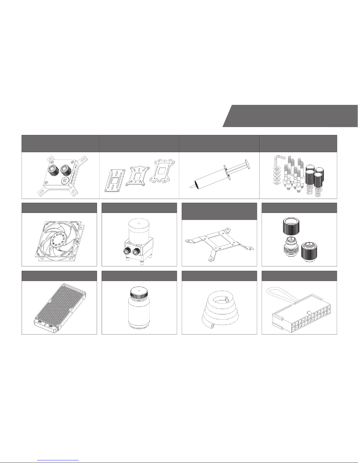
SCOPE OF DELIVERY
CPU water Block
with AMD® mounting plate CPU Backplate mechanism Thermal grease
Radiator
Fans Pump-Reservoir combo UNI Pump Bracket
(120mm Fan)
Compression fittings
CPU Mounting mechanism
Coolant Tube ATX Bridging plug
/ 4 /
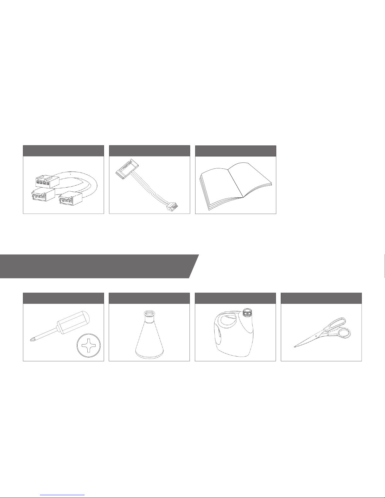
REQUIRED TOOLS
Fan cable Y-splitter Adapter cable Installation manual
Pair of scissors1L Bottle of distilled water
H20
Phillips-head screwdriver Mixing bottle

/ 5 /
RADIATOR SPACE CONSTRAINT REQUIREMENTS
280 mm (11,02 in)
160 mm (6,30 in)
120 mm (4,72 in)
27,5 mm (1,08 in)
240 120
120 mm (4,72 in)
/ 6 /
DOZEN GOOD ADVICES FOR THE NEWCOMERS
1. In order to make the package more compact we have decided to enclose
only the coolant concentrate for liquid cooling. Therefore you need to provide
1 liter (1L) of distilled water. You can get it at every gas station or supermarket.
2. Never run this system on tap water and always use the enclosed cooling
concentrate in correct ratio.
3. Never use alcohol, alcohol derivatives or alcohol based solvents in the
system. Using alcohol might result in permanent damage to water cool-
ing KIT components, especially acrylic parts of the system.
4. Reservoir must be positioned above the height level of the water pump
in order for liquid to flood the pump which is crucial for the fi rst start-up.
5. Generally, for optimal performance, the Reservoir must be positioned be-
fore the pump in the water loop.
6. Generally, for optimal performance, the CPU water block should be right
after the Radiator in the water loop.
7. Generally, for optimal performance, the Pump should be positioned be-
fore the Radiator in the water loop.
8. It is best practice to do a proper leak test before using your computer.
9. If you spot any leaks, turn off the power immediately!
10. Optimize tubing length in order to prevent excessive bending and kinking
of the tubing.
11. Never let your pump run dry. If this is happening for a prolonged pe-
riod of time you may risk destroying water pump’s bearing, rendering the
pump useless.
12. You are encouraged to periodically clean the radiator assembly as it will
collect dust over time. This is best done with soft wide tip brush and
vacuum cleaner. See chapter ‘General liquid cooling parts cleaning guide.
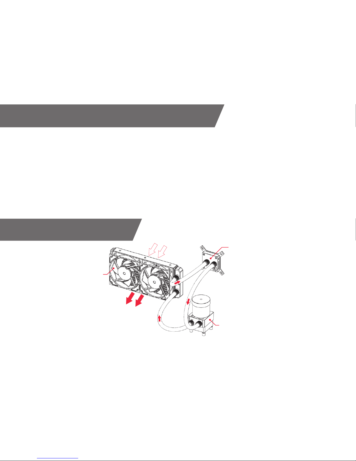
LIQUID COOLING SYSTEM
CPU WATERBLOCK
RESERVOIR-WATER PUMP COMBO
RADIATOR with FANS
COLD AIR
HOT AIR
/ 7 /
GENERAL INFORMATION ON WATER BLOCK COMPATIBILITY
This CPU liquid cooling unit is pre-assembled for use with modern Intel® and
AMD® desktop socket type motherboards. By default (out of the box) this water
block supports the following CPU sockets:
- Intel® Socket LGA-115x
- Intel® Socket LGA-2011(-3)
- AMD® Socket AM4*
*requires replacing Intel® mounting plate with AMD® one.
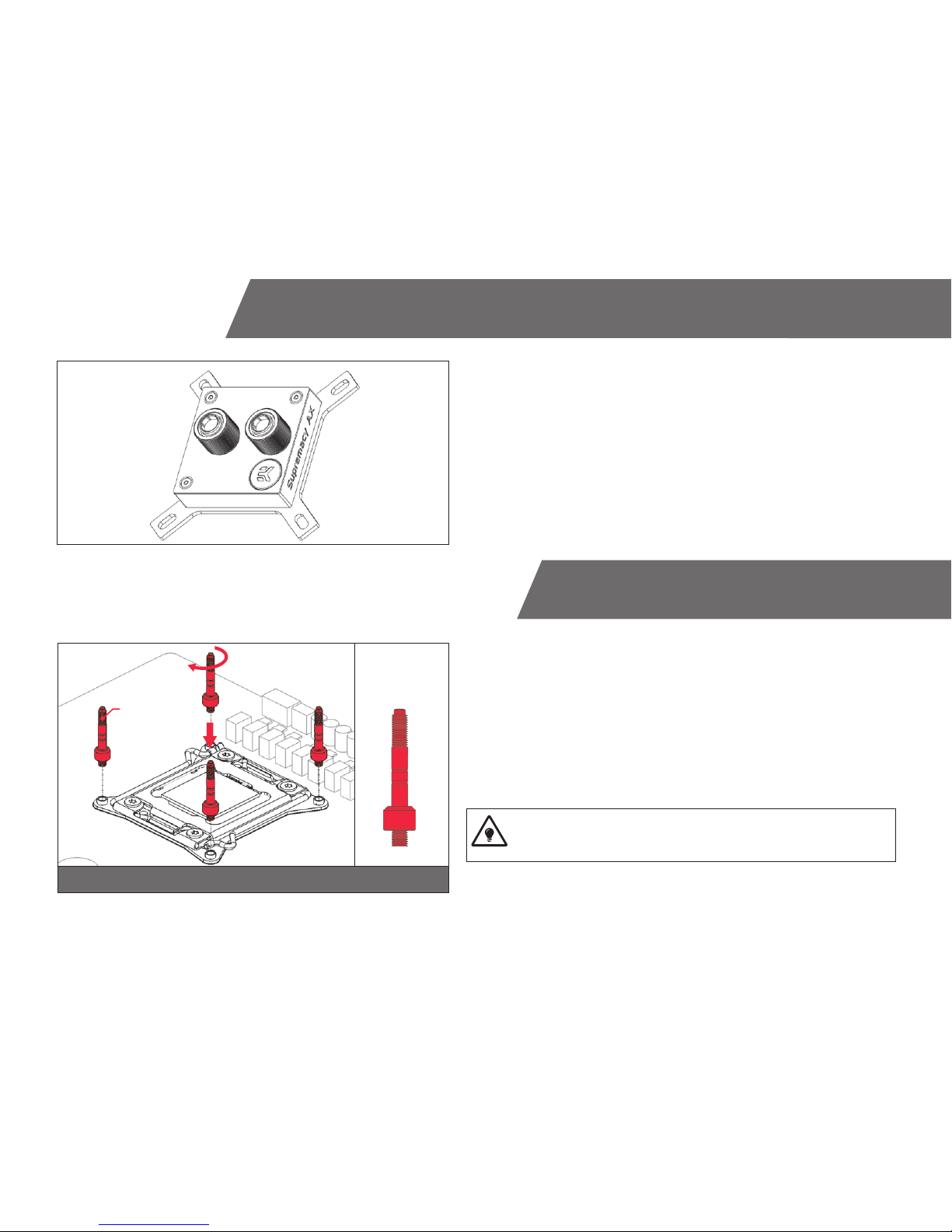
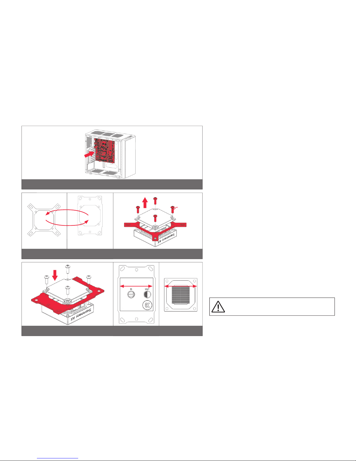
LGA-2011(-3) SOCKET MOTHERBOARDS
STEP 1
Prepare the foil bag with mounting mechanism, which is enclosed with the CPU
water block delivery.
Install four (4) specific LGA-2011 M4 thumb screws into four M4 threaded stubs
on the LGA-2011 socket integrated latch mechanism (ILM). The screws are to be
installed using no tools (i.e. pliers).
It is recommended to remove the motherboard form the PC chassis
before proceeding with installation of the CPU water block because of
the space constraint limitations of various computer cases.
STEP 1
LGA-2011 M4
Thumb Screw
LGA-2011 M4
Thumb Screw
INSTALLING THE WATER BLOCK
/ 8 /
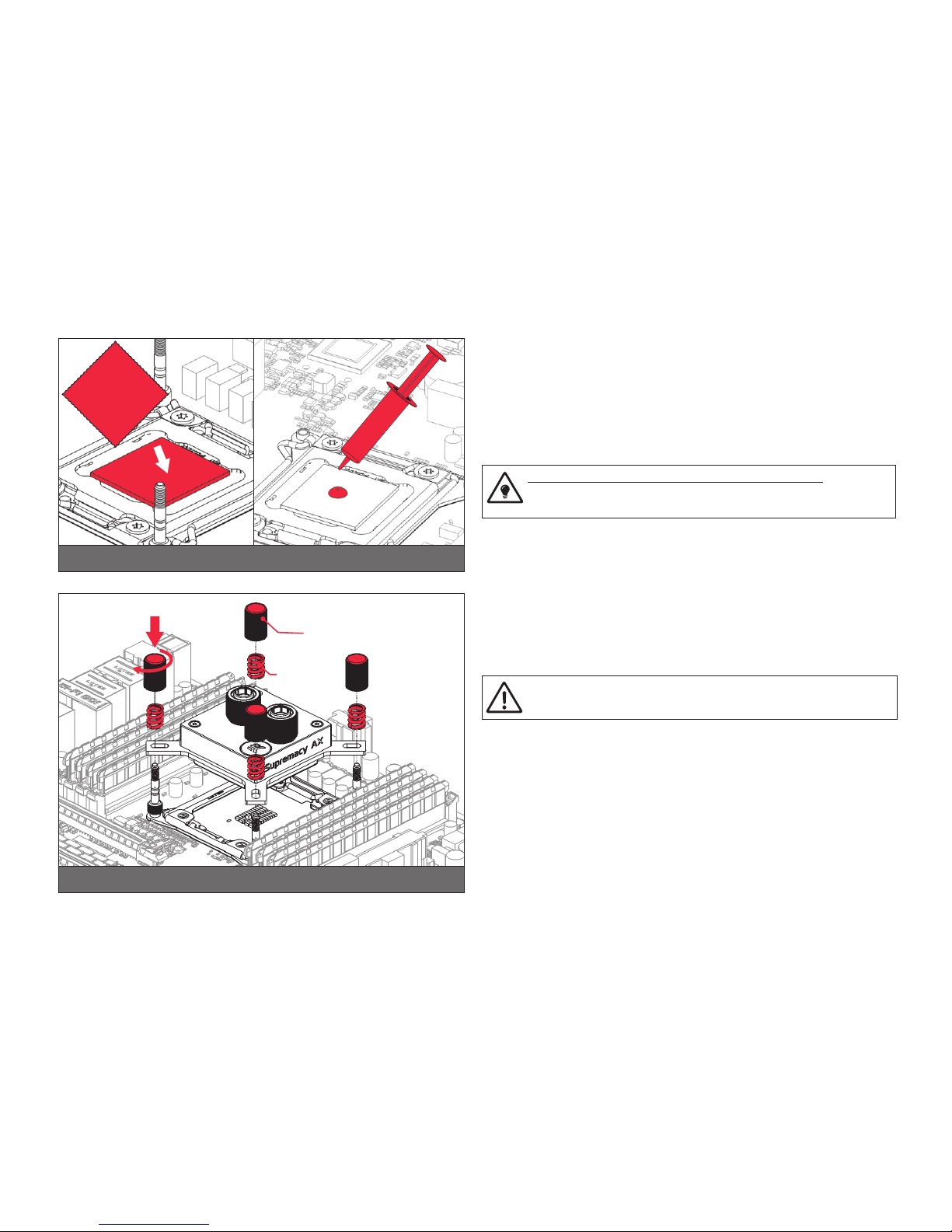
STEP 2
Cleaning the CPU: Wipe the CPU’s contact surface (by using non–abrasive
cloth or Q-tip, as shown on sample photo).
Applying thermal compound: EK recommends blob or line method of ap-
plying the enclosed EK-TIM Ectotherm thermal compound to the CPU heat
spreader (IHS) - see sample photo on right.
The quantity of about two rice grains is just about right. There is no
need to cover the whole IHS. Applying too much thermal grease will
have negative impact on the cooling performance!
STEP 2
Non-abrasive
cloth
Thermal grease
IHS
STEP 3
Take the waterblock and remove the sticker on the aluminum head.
Align the water block over the mounting screws on the LGA-2011(-3)
motherboard with pre-installed CPU.
Before proceeding with the installation It is mandatory to remove the
protective foil from the backside of the water block.
Place an enclosed compression spring and thumb nut over each M4 thumb
screw. Start fastening two thumb nuts at a time, preferably in cross pattern
and do not tighten them fully until all of them are partially screwed in. Then -
using your fingers only - screw in all four thumb nuts until you reach the end
of the thread.
STEP 3
Thumb nut
Coiled
spring

/ 9 /
LGA-115x SOCKET MOTHERBOARDS
STEP 1
If already installed, please remove the motherboard from your computer
and place it on an even surface with front facing down.
STEP 2
Preparing backplate rubber gasket
The enclosed rubber gasket is essential part of the backplate and mount-
ing system and must be used every time you install this water block on
your motherboard.
The rubber gasket has a partially cut inner part which needs to
be removed when installed on Intel LGA-115x motherboard. The
rubber is held on four places and can be peeled away with hand.
STEP 2STEP 1
Outer part
Inner core
(removable)
STEP 3
Install backplate rubber gasket and place metal backplate for Intel LGA-115x
socket to the back of your motherboard RIBBED SIDE UP! (facing away
from the motherboard) Align the holes on the motherboard with holes on
rubber gasket and backplate.
Make sure to orientate the rubber gasket to fit past the CPU
socket ILM backplate. On certain ITX form factor motherboards
the rubber gasket may need to be trimmed using household
scissors.
Carefully rotate motherboard assembly with front side facing up with one
hand while holding the backplate and rubber in place with the other hand.
STEP 4
Install four (4) M4 thumb screws onto your motherboard. It is mandatory
to put 0.7mm plastic washer underneath each of the M4 thumb screws.
Tighten the screws to the metal backplate until you reach the end of the
thread. Using tools (such as pliers) is not recommended.
STEP 3 STEP 4
Rubber gasket
Motherboard
Metal
Backplate M4 Thumb
Screw
PVC
washer
/ 10 /
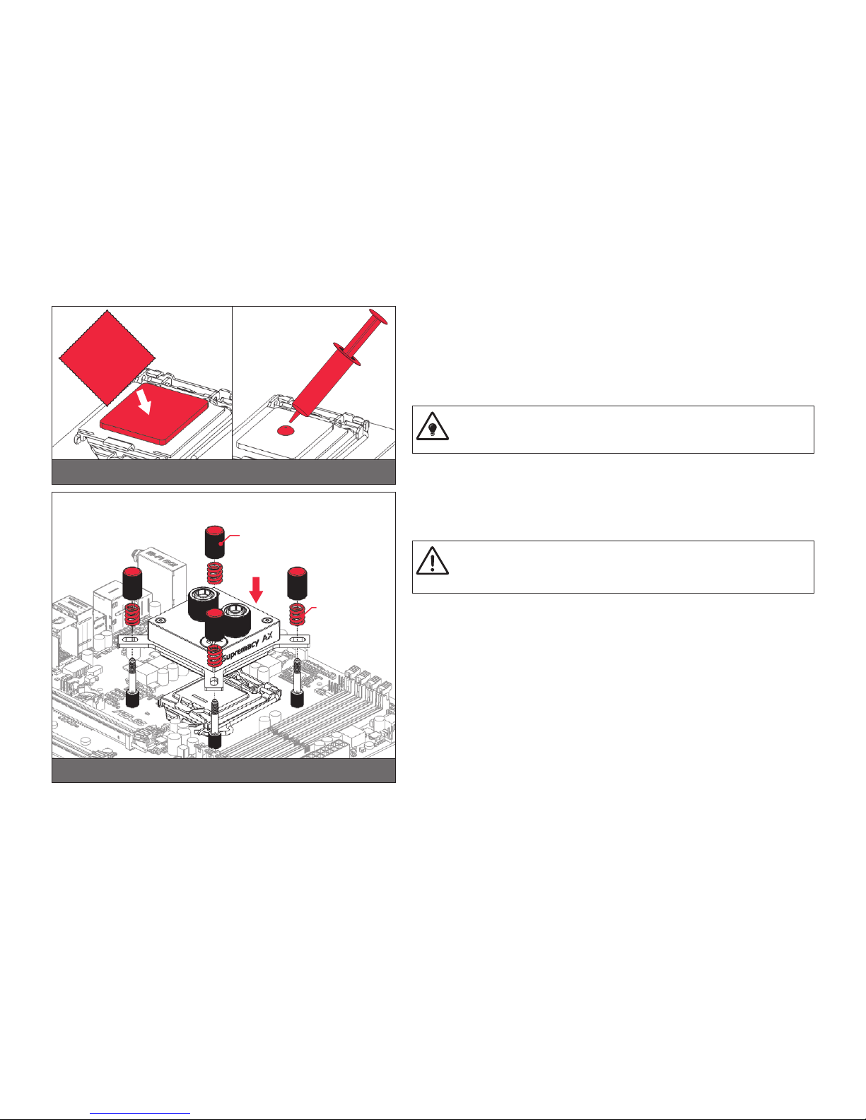
STEP 6
Align the water block over the mounting screws on the LGA-115x motherboard with
pre-installed CPU.
Before proceeding with the installation It is mandatory to remove the pro-
tective foil from the backside of the water block, as well as warning label
from the front of the waterblock!
Place an enclosed coiled spring and thumb nut over each M4 thumb screw. Start
fastening two thumb nuts at a time, preferably in cross pattern and do not tighten
them fully until all of them are partially screwed in. Then – using your fingers only
screw in all four thumb nuts until you reach the end of the thread.
STEP 5
Non-abrasive
cloth
Thermal grease
IHS
STEP 5
Cleaning the CPU: Wipe the CPU’s contact surface (by using non–abrasive cloth
or Q-tip, as shown on sample photo).
Applying thermal compound: EK recommends blob or line method of applying the
enclosed EK-TIM Ectotherm thermal compound to the CPU heat spreader (IHS) -
see sample photo on right.
The quantity of about two rice grains is just about right. There is no need to
cover the whole IHS. Applying too much thermal grease will have negative
impact on the cooling performance!
STEP 6
Thumb nut
Coiled spring
/ 11 /
STEP 7
STEP 7
Install the CPU water block along with the motherboard back into
the computer chassis.
The installation of the CPU water block is now complete.
AMD® SOCKET AM4
MOTHERBOARDS
STEP 1
Replacing the mounting plate:
Place the water block on a neven surface and remove the four
M4x12 screws attaching the aluminum base to the top using
2,5mm Allen key in counter-clockwise direction.
STEP 2
Replace the Intel factory installed mounting plate with AMD®
one. You will feel the mounting plate locking into the position
when placed correctly on to the top.
Reseat the O-ring gasket (57x2,2mm) into the gap between
the mounting plate and water block top.
Be careful that the orientation of the aluminum base
is as shown on the picture
Reinstall the M4x12 screws and tighten them using 2,5mm Al-
len key to screw them in clockwise direction.
STEP 1
STEP 2
Intel® socket
mounting plate
AMD® socket
mounting plate
M4x14
Screws
Orientation of the
aluminum base
/ 12 /
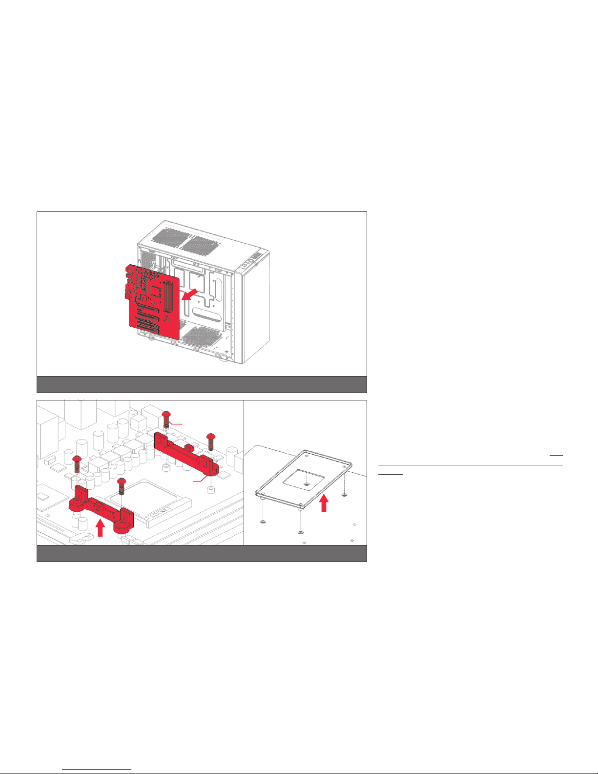
STEP 3
If already installed, please remove the motherboard
from your computer and place it on an even surface
with front facing up.
STEP 4
AMD® factory backplate
UNC 6-32
Screws
Hold-down
clamps
STEP 3
STEP 4
Removing of the original plastic hold-down clamps
and the factory backplate:
Using Philips-head screwdriver remove the four UNC
6-32 screws securing the original plastic hold-down
clamps around the socket as shown on the sketch. Re-
move the original AMD® backplate and the hold-down
clamps and store them away. See sketch for further part
identification.

/ 13 /
STEP 5 STEP 6
Outer part
Inner
core
(removable) Motherboard
Metal
Backplate
Rubber
gasket
AM4 STEP 5
Preparing backplate rubber gasket
The enclosed rubber gasket is essential part of
the backplate and mounting system and must be
used every time you install this water block on your
motherboard.
With AMD® Sockets you should use whole
rubber backplate including the inner core.
STEP 6
Install backplate rubber gasket and place metal back-
plate for AMD® AM4 socket to the back of your moth-
erboard RIBBED SIDE UP! (facing away from the
motherboard) Align the holes on the motherboard with
holes on rubber gasket and backplate.
Carefully rotate motherboard assembly with front side
facing up with one hand while holding the backplate and
rubber in place with the other hand.
STEP 7
Install four (4) M4 thumb screws onto your mother-
board. It is mandatory to put 0.7mm plastic washer un-
derneath each of the M4 thumb screws. Tighten the
screws to the metal backplate until you reach the end
of the thread. Using tools (such as pliers) is not recom-
mended.
STEP 7
M4 Thumb Screw
PVC
washer

/ 14 /
STEP 9
Thumb nut
Coiled spring
STEP 8
Non-abrasive
cloth
IHS
Thermal grease
STEP 8
Cleaning the CPU: Wipe the CPU’s contact surface (by using non–abrasive
cloth or Q-tip, as shown on sample photo).
Applying thermal compound: EK recommends blob or line method of ap-
plying the enclosed EK-TIM Ectotherm thermal compound to the CPU heat
spreader (IHS) - see sample photo on right.
The quantity of about two rice grains is just about right. There is no
need to cover the whole IHS. Applying too much thermal grease will
have negative impact on the cooling performance!
STEP 9
Align the water block over the mounting screws on the AMD socket mother-
board with pre-installed CPU.
Before proceeding with the installation It is mandatory to remove
the protective foil from the backside of the water block, as well as
warning label from the front of the waterblock!
Place an enclosed coiled spring and thumb nut over each M4 thumb screw.
Start fastening two thumb nuts at a time, preferably in cross pattern and do
not tighten them fully until all of them are partially screwed in.
Then – using your fingers only screw in all four thumb nuts until you reach the
end of the thread.

/ 15 /
STEP 10
Install the CPU water block along with the motherboard back into the com-
puter chassis.
The installation of the CPU waterblock is now complete.
STEP 10
INSTALLING THE RADIATOR AND FANS
OPTION #1:
INSTALLING THE RADIATOR AND FANS
STEP 1
Install the fans on the radiator.
Ideally, the radiator should either:
A) receive the coldest air possible (by placing the radiator on
the air inlet) or
B) serve as an overall hot air exhaust (by placing the radiator on
the exhaust).
The latter results in overall decrease of temperature throughout the
entire computer chassis but also leads to slightly higher liquid tem-
peratures. A reversed air flow is viable option but one should always
strive to achieve unidirectional flow of air throughout the chassis.
Take the four UNC 6-32x30mm screws for each fan and screw them in. Use
enclosed Allen key to tighten the screws in clockwise direction.
STEP 1
Fan
UNC 6-32 x 30 screw
Radiator
/ 16 /
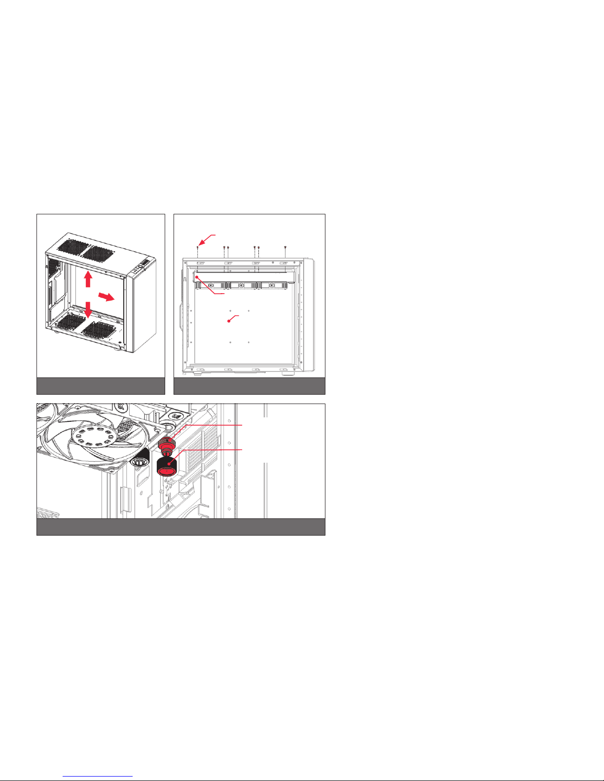
STEP 2
Prepare your suitably-sized PC chassis for installation of radiator
unit. The position of the unit in the chassis depends on the size, fan
mounting holes and the hardware you have installed. You must make
sure that the unit fits into the chassis. Usually the chassis have stand-
ard fan mounting holes pre-drilled so you should look for holes with
spacing of 105mm. (A standard computer cooling 120mm fan)
STEP 3
Align the holes on the radiator with the ones on the PC chassis.
Take the four UNC 6-32x5mm screws for each fan and guide them
through the holes on the chassis to screw them into the threaded holes
on the radiator. Tighten them in clockwise direction using Allen key.
STEP 4.:
Install the compression fitting on both G1/4 extender openings on
the radiator. Tighten the fitting barbs in clockwise direction until the
gasket underneath is compressed.
The installation of the radiator and radiator cooling fans is now complete.
STEP 2 STEP 3
PC Chassis
Radiator/fan unit
UNC 6-32 x 5
screw
STEP 4
Fitting Barb
Fitting Ring
/ 17 /
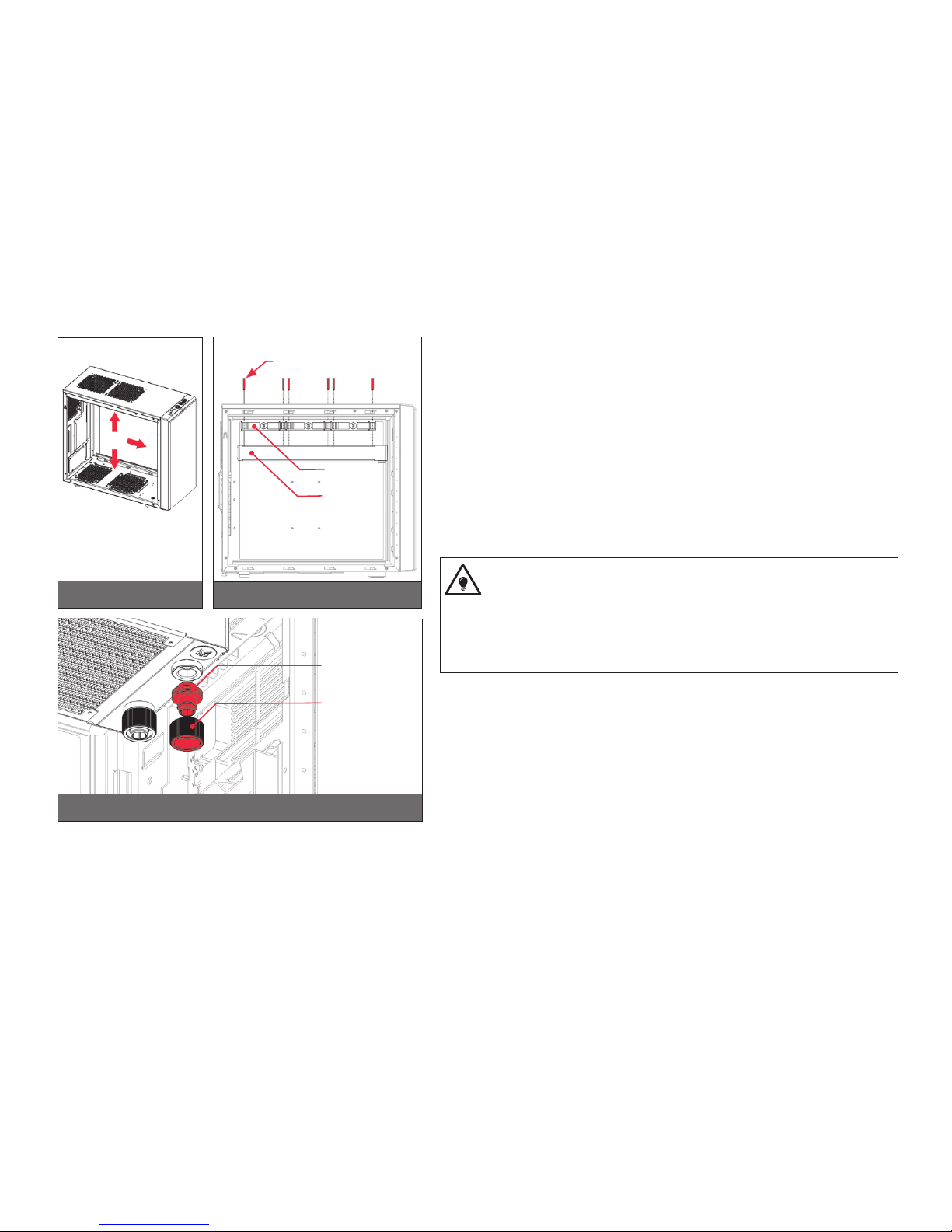
OPTION #2:
INSTALLING THE RADIATOR AND FANS IN
ONE GO
STEP 1.:
Prepare your suitably-sized PC chassis for installation of radiator unit. The position
of the unit in the chassis depends on the size, fan mounting holes and the hardware
you have installed. You must make sure that the unit fits into the chassis. Usually the
chassis have standard fan mounting holes pre-drilled so you should look for holes with
spacing of 105mm. (A standard computer cooling 120mm fan)
STEP 2.:
Align the holes on the fans and the radiator with the ones on the PC chassis.
Ideally, the radiator should either:
A) receive the coldest air possible (by placing the radiator on the air inlet) or
B) serve as an overall hot air exhaust (by placing the radiator on the exhaust).
The latter results in overall decrease of temperature throughout the entire
computer chassis but also leads to slightly higher liquid temperatures. A re-
versed air flow is viable option but one should always strive to achieve unidi-
rectional flow of air throughout the chassis.
Take the four UNC 6-32x30mm screws for each fan and guide them through the holes
on the chassis and fans to screw them into the threaded holes on the radiator. Tighten
them in clockwise direction using enclosed Allen key.
STEP 3.:
Install the compression fitting on both G1/4 extender openings on the radiator. Tighten
the fitting barbs in clockwise direction until the gasket underneath is compressed.
The installation of the radiator and radiator cooling fans is now complete.
STEP 1 STEP 2
Fan
UNC 6-32 x 30 screw
Radiator
STEP 3
Fitting Barb
Fitting Ring
/ 18 /
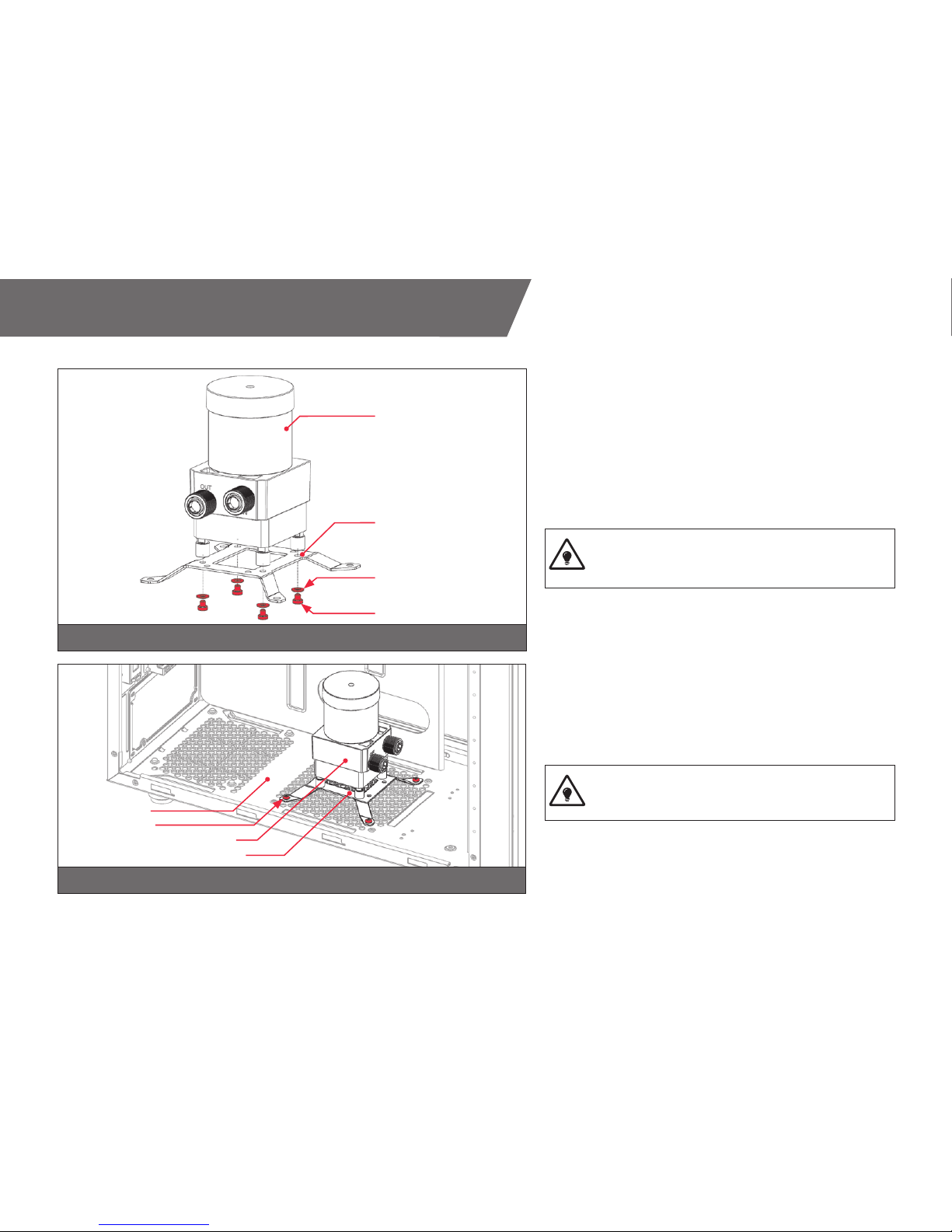
INSTALLING THE PUMP-RESERVOIR UNIT
STEP 1
The KIT comes with combined pump and reservoir unit with pre-
installed anti-vibration decouplers.
Take the unit and place it on the EK-UNI Holder DDC Spider
(120mm FA N)
Secure it from the bottom side using four M4x4 screws and PVC
washers. Tighten them in clockwise direction using enclosed
2,5mm Allen key.
This unit can be installed anywhere where there is a
50x50mm square mounting hole pattern on the chas-
sis without using any pump bracket.
STEP 2
The position of the unit in the chassis depends on the fan mount-
ing holes and the hardware you have installed. Usually the chassis
have Pre-drilled standard fan mounting holes on the bottom one
should look for holes with spacing of 105mm. (A standard com-
puter cooling 120mm fan).
Alternatively you can drill four Ø4,5mm holes using
electric power drill to the most suitable place on the bot-
tom of your computer chassis.
Put four M4x6 DIN7984 screws through the holes on the UNI
pump bracket from the upper side.
STEP 1
STEP 2
Pump-reservoir
combo unit
120mm fan UNI
pump bracket
PVC washer
M4x4 screw
PC Chassis
Pump-reservoir combo unit
120mm fan UNI pump bracket
M4x6 screw
This manual suits for next models
2
Table of contents
Other Fluid Gaming Computer Accessories manuals

Popular Computer Accessories manuals by other brands


Pinnacle
Pinnacle PCTV DVB-T Flash Stick quick start guide

Rapoo
Rapoo N1850 manual

Texas Instruments
Texas Instruments PHP1800 operating instructions

Trust
Trust 310KD instruction manual

Logitech
Logitech 967224-0403 - Cordless Access Duo Wireless... Setup guide

CORE AUDIO
CORE AUDIO DAIDO Barebone Entry Technical Specifications and Installation Guidelines


