2E GAMING CALLEO User manual

RU
UA
EN
КЕРІВНИЦТВО ПО ВИКОРИСТАННЮ
КОМП’ЮТЕРНОГО КОРПУСА
РУКОВОДСТВО ПО ЭКСПЛУАТАЦИИ
КОМПЬЮТЕРНОГО КОРПУСА
COMPUTER CASE OPERATION GUIDE
2E GAMING CALLEO GB700

2
UA
Виріб: комп’ютерний корпус.
Призначення: для розміщення компонентів системи персонального комп’ютера.
Модель: 2Е-GB700.
СПЕЦИФІКАЦІЯ
Вид Mini Tower (Micro ATX)
Матеріал Пластик, сталь, загартоване скло
(бокова (ліва) панель)
Материнські плати Micro ATX Mini ITX
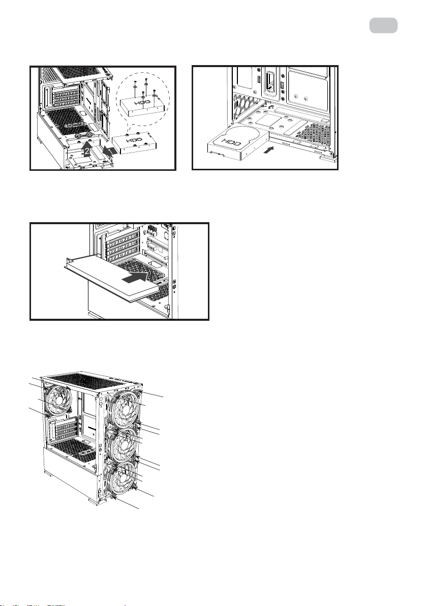
Зовнішні відсіки 5.25’’ немає
Внутрішні відсіки 2.5’’ 2 (3) шт.
Внутрішні відсіки 3.5’’ 2 (1) шт.
Слоти розширення 4 шт.
Вентилятори опціонально, мм
Передня панель: 3х 120 або 2х 140
Бічна панель: немає
Задня панель: 1x 120
Верхня панель: 2х 120
Радіатори опціонально, мм
Передня панель: 240
Бічна панель: немає
Задня панель: 120
Верхня панель: немає
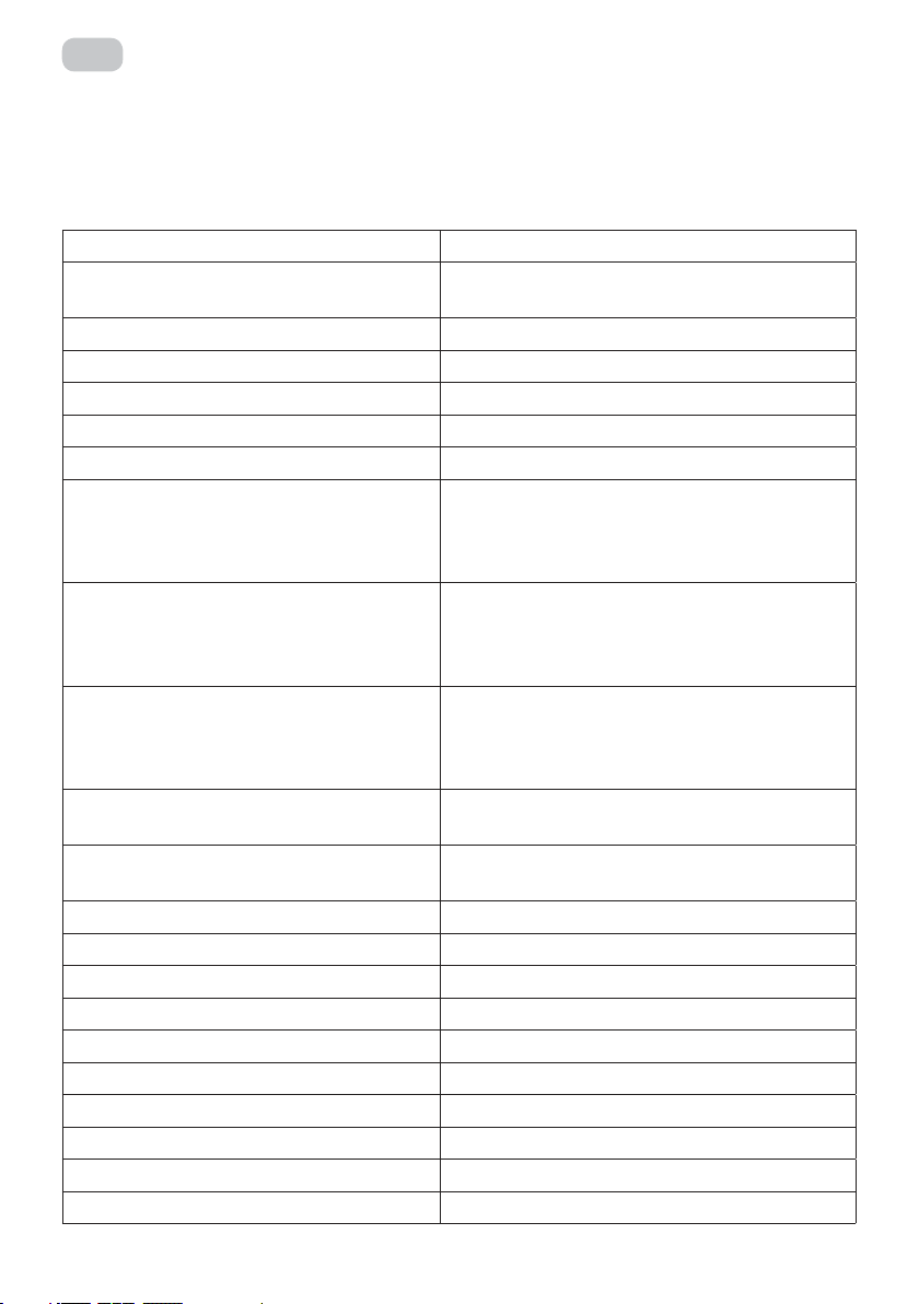
Вентилятори встановлені, мм
Передня панель: 3х 120 ARGB 6pin
Бічна панель: немає
Задня панель: 1х 120 ARGB 6pin
Верхня панель: немає
Концентратор для підключення
вентиляторів
Контролер з пультом дистанційного
керування
Розніми, кнопки 1хUSB2.0, 2хUSB 3.0, HD Audio+MIC / Power,
Reset, Power LED, HDD LED
Блок живлення, Вт / розміщення Немає / Знизу
Максимальна довжина VGA, мм 320
Висота CPU кулера, мм 150
Пиловий фільтр Верхня / нижня панелі
Розмір (ШхВхГ), мм 200x393x361
Розмір пакування (ШхВхГ), мм 260x425x453
Вага без пакування, кг 4.1
Вага з пакуванням, кг 4.9
Країна виробник Китай
Гарантія 12 місяців

3
UA
ОПИС
1. :
1(а) металева сітка;
1 (b) місце для вентиляторів.
2. :
2(a) місце для блока живлення;
2(b) місце для вентилятора;
2(c) cлоти розширення для відеокарти, мережевої карти, модема, звукової карти та інше.
3. : місце для розміщення материнської плати.
4. :
4(a) 2.5’’;
4(b) 3.5’’.
5. :
5(а) 1хUSB2.0, 2хUSB 3.0, HD Audio+MIC / Power, Reset, Power LED, HDD LED;
5(b) пиловий фільтр.
6. (): загартоване скло.
* Зовнішній вигляд та комплектація виробу може бути доповнені чи змінені, з метою його
вдосконалення чи поліпшення якості товару.
Передня панель
3
6
5 (a)
5 (b)
Основна частина
Бічна панель
(ліва) 4 (b)
1 (b)
2 (b)
2 (c)
2 (a)
4 (a)
4 (a)
4 (a)
4 (b)
1 (а)

4
UA
1 – Встановлення материнської плати.
2 – Встановлення блоку живлення.
ВСТАНОВЛЕННЯ КОМПОНЕНТІВ СИСТЕМИ
КОМПЛЕКТАЦІЯ
Motherboard InstallationEvery motherboard has different specifications for the installment of stand-offs, it is strongly recommended that you refer to your motherboard’s instruction manual when nstalling stand-offs to the case.Power Supply InstallationSecurely install the power supply at the top of the case and tighten it with screws on position .Graphics Card InstallationInstall the graphics card on the PCI slot following the indicated direction and tighten it with screws3.5’’ HDD InstallationInstall the HDD on the indicated position and tighten it with screws.2.5’’ SSD InstallationInstall the SSD on the indicated positions and tighten them with screwsFans InstallationFront: 120mm fan x 3Rear: 120mm fan x 1HDD Installation (1)HDD Installation (2)SSD Installation (1)SSD Installation (2)(1)
3 – Встановлення 2.5’’ SSD.
Наіменування Кількість шт.
Гвинт для установки MB та 2.5’’HDD 14
Гвинт для установки PSU 6
MB кріплення 2
Гвинт для встановлення HDD 3.5’’ 8
Cтяжки 3
Пульт дистанційного керування 1
Контролер із портами для підключення
вентиляторів 1

5
UA
5 – Встановлення 3.5’’ HDD.
6 – Встановлення VGA.
7 – Встановлення вентиляторів.
Motherboard InstallationEvery motherboard has different specifications for the installment of stand-offs, it is strongly recommended that you refer to your motherboard’s instruction manual when nstalling stand-offs to the case.Power Supply InstallationSecurely install the power supply at the top of the case and tighten it with screws on position .Graphics Card InstallationInstall the graphics card on the PCI slot following the indicated direction and tighten it with screws3.5’’ HDD InstallationInstall the HDD on the indicated position and tighten it with screws.2.5’’ SSD InstallationInstall the SSD on the indicated positions and tighten them with screwsFans InstallationFront: 120mm fan x 3Rear: 120mm fan x 1HDD Installation (1)HDD Installation (2)SSD Installation (1)SSD Installation (2)(1)

6
RU
ПІДКЛЮЧЕННЯ ТА РОБОТА ВЕНТИЛЯТОРІВ - КОНТРОЛЕР
ІНСТРУКЦІЯ
ARGB вентилятори / схема підключення до контролера
Блок
живлення
LED стрічка (підключення)

7
UA
СПЕЦИФІКАЦІЯ
Швидкість вентилятора (RPM)
Рівень шуму (dBA)
Продуктивність вентилятора (CFM)
Напруга живлення (V)
Сила струму (А)
Потужність (W)
Конектор
Розмір вентилятора, мм
Довжина дроту, мм
1200± 10%
≤ 26
55
12
0.26-0.48
3.12-5.76
6pin
120 x 120 x 25 мм
450 мм
ПУЛЬТ ДИСТАНЦІЙНОГО УПРАВЛІННЯ/ОСНОВНІ ФУНКЦІЇ
Контроль звуку - режим 1
Жовтий
Помаранчевий
Червоний
Швидкість обертів
зменшити
Швидкість обертів
збільшити
ВКЛ
Контроль звуку - режим 2
Салатовий
Голубий
Зелений
Перемикач режимів-
Перемикач режимів+
Автоматичній режим
Контроль звуку - режим 3
Рожевий
Фіолетовий
Синій
Зменшити яскравість
Збільшити яскравість
ВИКЛ
1. Підключити вентилятори до контролера у зазначені конектори - FAN1-FAN10.
2. Підключити контролер до блоку живлення.
3. Натиснути кнопку ON на пульті управляння для початку роботи.
4. Додатково до контролера можливо під’єднати LED стрічки та синхронізувати
підсвічення із вентиляторами.

8
UA
УМОВИ ЕКСПЛУАТАЦІЇ ТА ЗАХОДИ БЕЗПЕКИ
1) Перед початком експлуатації необхідно пересвідчитись у наявності всіх необхідних деталей.
2) Під час складання, використовуйте рукавички, щоб не пошкодити руки.
3) Не застосовуйте надмірну силу для закріплення компонентів, щоб не пошкодити корпус
або кріплення.
4) Необхідно пересвідчитись у тому, що всі складові виробу не пошкоджені та справно
функціонують.
5) Не використовуйте для догляду за виробом абразивні та агресивні засоби очистки, щоб
уникнути подряпин чи пошкодження поверхні.
6) Зберігати та використовувати в недоступних для дітей та тварин місцях.
ЗБЕРІГАННЯ,ТРАНПОРТУВАННЯ ТА УТИЛІЗАЦІЯ
1) Здійснювати транспортування виробу в оригінальній упаковці, щоб уникнути
пошкодження.
2) Якщо в корпусі вже встановлені комплектуючі, перевірте наскільки надійно вони
закріплені або демонтуйте їх та приготуйте корпус до транспортування.
3) Уникайте потрапляння вологи та води на поверхню або в середину корпусу, щоб
запобігти корозії матеріалу.
4) Утилізувати корпус та його пакування згідно правил утилізації в вашій країні.
Дистанційний пульт керування
Живлення: Батарея типу 3 В CR2025
Встановлення та заміна елементу живлення:
Місце для розміщення батареї - зворотня сторона корпусу пульту дистанційного керування.
Натиснути на пластиковий елемент конструкції та відкрити відсік для батареї.
Встановити батарею
Зачинити відсік для батареї
Увага! Зберігати та використовувати пристрій в недоступних для дітей та тварин місцях.
Уникайте потрапляння вологи та води на поверхню чи в середину корпусу пульта дистан-
ційного керування/контролера. Утилізувати пристрій, батарейку та його пакування згідно
правил утилізації в вашій країні.

9
RU
Изделие: компьютерный корпус.
Назначение: для размещения компонентов системы персонального компьютера.
Модель: 2Е-GB700.
СПЕЦИФИКАЦИЯ
Тип Mini Tower (Micro ATX)
Материал Пластик, сталь, закаленное стекло (боковая
(левая) панель)
Материнские платы Micro ATX Mini ITX
Внешние отсеки 5.25’’ нет
Внутренние отсеки 2.5’’ 2 (3) шт.
Внутренние отсеки 3.5’’ 2 (1) шт.
Слоты расширения 4 шт.
Вентиляторы (опционально), мм
Передняя панель: 3х 120 или 2х 140
Боковая панель: нет
Задняя панель: 1x 120
Верхняя панель: 2х 120
Радиаторы опционально, мм
Передняя панель: 240
Боковая панель: нет
Задняя панель: 120
Верхняя панель: нет
Вентиляторы установленные, мм
Передняя панель: 3х 120 ARGB 6pin
Боковая панель: нет
Задняя панель: 1х 120 ARGB 6pin
Верхняя панель: нет
Концентратор для подключения
вентиляторов
Контроллер с пультом дистанционного
управления
Разъемы, кнопки 1хUSB2.0, 2хUSB 3.0, HD Audio+MIC / Power, Reset,
Power LED, HDD LED
Блок питания, Вт / расположение Нет / Нижнее
Максимальная длина VGA, мм 320
Высота CPU кулера, мм 150
Пылевой фильтр Верхняя/нижние панели
Размеры (ШxВxГ), мм 200x393x361
Размеры упаковки (ШxВxГ), мм 260x425x453
Вес без упаковки, кг 4.1
Вес с упаковкой, кг 4.9
Страна производитель Китай
Гарантия 12 месяцев

10
RU
ОПИСАНИЕ
* Внешний вид и комплектация товара могут быть дополнены или изменены с целью его усовершен-
ствования или улучшения качества товара.
1. :
1(а) металлическая сетка;
1(b) Место для вентиляторов.
2. :
2(a) место для блока питания;
2(b) место для вентилятора;
2(c) cлоты расширения для видеокарты, сетевой карты, модем, звуковой карты и др.
3. : место для расположения материнской платы.
4. :
4(a) 2.5’’;
4(b) 3.5’’.
5. :
5(а) 2
xUSB 2.0, 1xUSB 3.0, HD Audio+MIC / Power, Reset, Power LED, HDD LED
;
5(b) пылевой фильтр.
6. (): закаленное стекло.
7.
().
Передняя панель
3
6
5 (a)
5 (b)
Основная часть
Боковая
панель
(левая)
4 (b)
1 (b)
2 (b)
2 (c)
2 (a)
4 (a)
4 (a)
4 (a)
4 (b)
1 (а)

11
RU
УСТАНОВКА КОМПОНЕНТОВ СИСТЕМЫ
КОМПЛЕКТАЦИЯ
1 – Установка материнской платы.
2 – Установка блока питания.
Motherboard InstallationEvery motherboard has different specifications for the installment of stand-offs, it is strongly recommended that you refer to your motherboard’s instruction manual when nstalling stand-offs to the case.Power Supply InstallationSecurely install the power supply at the top of the case and tighten it with screws on position .Graphics Card InstallationInstall the graphics card on the PCI slot following the indicated direction and tighten it with screws3.5’’ HDD InstallationInstall the HDD on the indicated position and tighten it with screws.2.5’’ SSD InstallationInstall the SSD on the indicated positions and tighten them with screwsFans InstallationFront: 120mm fan x 3Rear: 120mm fan x 1HDD Installation (1)HDD Installation (2)SSD Installation (1)SSD Installation (2)(1)
3 – Установка 2.5’’ SSD.
Название Количество шт.
Винт для установки MB и 2.5’’HDD 14
Винт для установки PSU 6
MB крепление 2
Винт для установки HDD 3.5’’ 8
Cтяжки 3
Пульт дистанционного управления 1
Контроллер с портами для подключения
вентилятора 1

12
RU
5 – Установка 3.5’’ HDD.
6 – Установка VGA.
7 – Установка вентиляторов.
Motherboard InstallationEvery motherboard has different specifications for the installment of stand-offs, it is strongly recommended that you refer to your motherboard’s instruction manual when nstalling stand-offs to the case.Power Supply InstallationSecurely install the power supply at the top of the case and tighten it with screws on position .Graphics Card InstallationInstall the graphics card on the PCI slot following the indicated direction and tighten it with screws3.5’’ HDD InstallationInstall the HDD on the indicated position and tighten it with screws.2.5’’ SSD InstallationInstall the SSD on the indicated positions and tighten them with screwsFans InstallationFront: 120mm fan x 3Rear: 120mm fan x 1HDD Installation (1)HDD Installation (2)SSD Installation (1)SSD Installation (2)(1)

13
RU
ПОДКЛЮЧЕНИЕ И РАБОТА ВЕНТИЛЯТОРОВ - КОНТРОЛЛЕР
ИНСТРУКЦИЯ
ARGB вентиляторы / схема подключения к контроллеру
Блок
питания
LED лента (подключение)

14
RU
СПЕЦИФИКАЦИЯ
Скорость вентилятора (RPM)
Уровень шума (dBA)
Производительность вентилятора (CFM)
Напряжение питания (V)
Сила тока (А)
Мощность (W)
Коннектор
Размер вентилятора, мм
Длина провода, мм
ПУЛЬТ ДИСТАНЦИОННОГО УПРАВЛЕНИЯ/ОСНОВНЫЕ ФУНКЦИИ
Контроль звука- режим 1
Желтый
Оранжевый
Красный
Скорость оборотов
уменьшить
Скорость оборотов
увеличить
ВКЛ
Контроль звука- режим 2
Салатовый
Голубой
Зеленый
Переключение режимов-
Переключение режимов+
Автоматическй режим
Контроль звука- режим 3
Розовый
Фиолетовый
Синий
Уменьшить яркость
Увеличить яркость
ВЫКЛ
1. Подключить вентиляторы к контроллеру в обозначенные коннекторы
- FAN1-FAN10.
2. Подключить контроллер к блоку питания.
3. Нажать кнопку ON на пульте управления для начала работы.
4. Дополнительно к контроллеру можно подсоединить LED ленты и синхронизировать
их работу с подсветкой вентиляторов.
1200± 10%
≤ 26
55
12
0.26-0.48
3.12-5.76
6pin
120 x 120 x 25 мм
450 мм

15
RU
УСЛОВИЯ ЭКСПЛУАТАЦИИ И МЕРЫ ПРЕДОСТОРОЖНОСТИ
1) Убедитесь в наличие всех необходимых деталей, перед началом эксплуатации.
2) В процессе осуществления сборки, используйте перчатки, чтобы не повредить руки.
3) Не применяйте сверх усилий для закрепления компонентов, чтобы не повредить корпус
или крепления.
4) Убедитесь в том, что все составляющие изделия исправны и корректно функционируют.
5) Не используйте для ухода за изделием абразивные, отбеливающие чистящие средства,
чтобы избежать царапин и повреждений на поверхности.
6) Хранить и эксплуатировать в недоступном для детей и животных месте.
ХРАНЕНИЕ, ТРАНСПОРТИРОВКА И УТИЛИЗАЦИЯ
1) Транспортируйте изделие в оригинальной упаковке, чтобы избежать повреждений.
2) Если в корпусе уже установлены комплектующие, проверьте, насколько прочно они
закреплены, либо демонтируйте их и приготовьте корпус к перемещению.
3) Избегайте попадания влаги и воды на поверхность или во внутрь корпуса, чтобы
предотвратить коррозию материала.
4) Утилизируйте корпус и упаковочный материал согласно правил утилизации в вашей
стране.
Пульт дистанционного управления
Питание: батарея типа 3В 2025
Установка и замена элемента питания:
Место для размещения батареи - оборотная сторона корпуса пульта дистанционного
управления.
Нажать на пластиковый элемент конструкции и открыть отсек для батареи.
Установить батарею
Закрыть отсек для батареи
Внимание! Сохранять и использовать устройство в недоступных для детей и животных
местах. Избегать попадения влаги на поверхность или в середину корпуса пульта дистан-
ционного управления или контроллера. Утилизировать устройство, батарейку и упаковку,
согласно правил утилизции в вашей стране.

16
EN
Product: computer case.
Using: for placing components of personal computer system.
Model: 2Е-GB700.
SPECIFICATION
Type Mini Tower (Micro ATX)
Material Plastic, steel, tempered glass (side (left) panel)
Motherboards Micro ATX Mini ITX
External 5.25’’ non
Internal 2.5’’ 2 (3) pcs
Internal 3.5’’ 2 (1) pcs
Expansion slots 4 pcs
Optional fans, mm
Front panel: 3х 120 или 2х 140
Side panel: non
Rear panel: 1x 120
Top panel: 2х 120
Radiators, mm
Front panel: 240
Side panel: non
Rear panel: 120
Top panel: non
Included fans, mm
Front panel: 3х 120 ARGB 6pin
Side panel: non
Rear panel: 1х 120 ARGB 6pin
Top panel: non
HUB for fan connection ARGB controller with fan remote control
I/O Ports, buttons 1хUSB2.0, 2хUSB 3.0, HD Audio+MIC / Power, Reset,
Power LED, HDD LED
Power supplier, W / place Non / Bottom
Max VGA length, mm 320
CPU cooler height, mm 150
Dust lter Top/bottom panels
Size (WxHxL), mm 200x393x361
Package size (WxHxL), mm 260x425x453
Weight without package,kg 4.1
Weight with package,kg 4.9
County of origin Сhina
Warranty 12 months

17
EN
DISCRIPTION
1. Front panel:
1(а) metal mesh;
1(b) place for case fans.
2. Rear panel:
2(a) place for power supplier;
2(b) place for case fan;
2(c) expansion slots for VGA, network card, modem, audio card etc.
3. General part: place for motherboard;
4. Internal:
4(a) 2.5’’;
4(b) 3.5’’.
5. Top panel:
5(а) 1хUSB2.0, 2хUSB 3.0, HD Audio+MIC / Power, Reset, Power LED, HDD LED;
5(b) dust lter.
6. Side
panel (left): tempered glass.
* Appearance and equipment of item can be supplemented or modied for the purpose of the improvement
or for improvement of product quality.
Front panel
3
6
5 (a)
5 (b)
General part
Side panel
(left)
4 (b)
1 (b)
2 (b)
2 (c)
2 (a)
4 (a)
4 (a)
4 (a)
4 (b)
1 (а)

18
EN
SYSTEM COMPONENTS INSTALLATION
COMPLETE SET
1 – Motherboard installation.
2 – Power supply installation.
Motherboard InstallationEvery motherboard has different specifications for the installment of stand-offs, it is strongly recommended that you refer to your motherboard’s instruction manual when nstalling stand-offs to the case.Power Supply InstallationSecurely install the power supply at the top of the case and tighten it with screws on position .Graphics Card InstallationInstall the graphics card on the PCI slot following the indicated direction and tighten it with screws3.5’’ HDD InstallationInstall the HDD on the indicated position and tighten it with screws.2.5’’ SSD InstallationInstall the SSD on the indicated positions and tighten them with screwsFans InstallationFront: 120mm fan x 3Rear: 120mm fan x 1HDD Installation (1)HDD Installation (2)SSD Installation (1)SSD Installation (2)(1)
3 – 2.5’’ SSD installation.
Item name Quantity pcs
MB & 2.5’’ HDD installation screw 14
PSU installation screw 6
MB installation 2
3.5’’ HDD installation screw 8
Cable tie 3
Remote controller 1
Controller with ports for the fans 1

19
EN
5 – 3.5’’ HDD installation.
6 – VGA installation.
7 – Case fans installation.
Motherboard InstallationEvery motherboard has different specifications for the installment of stand-offs, it is strongly recommended that you refer to your motherboard’s instruction manual when nstalling stand-offs to the case.Power Supply InstallationSecurely install the power supply at the top of the case and tighten it with screws on position .Graphics Card InstallationInstall the graphics card on the PCI slot following the indicated direction and tighten it with screws3.5’’ HDD InstallationInstall the HDD on the indicated position and tighten it with screws.2.5’’ SSD InstallationInstall the SSD on the indicated positions and tighten them with screwsFans InstallationFront: 120mm fan x 3Rear: 120mm fan x 1HDD Installation (1)HDD Installation (2)SSD Installation (1)SSD Installation (2)(1)

20
EN
ARGB FAN CONNECTION DIAGRAM
INSTRUCTION
ARGB fan connection diagram
Power
supply
LED light bar
This manual suits for next models
1
Table of contents
Languages:
Other 2E Computer Accessories manuals