manuals.online logo
Brands
  1. Home
  2. •
  3. Brands
  4. •
  5. fluid-o-tech
  6. •
  7. Water Pump
  8. •
  9. fluid-o-tech MG Series User manual

fluid-o-tech MG Series User manual

Fluid-o-Tech Int’l Inc.
161 Atwater St.,
Plantsville CT (USA) 06479
Tel. +1 (860) 276 9270
Fax +1 (860) 620 0193
[email protected]
Fluid-o-Tech Int’l Inc. Japan
2nd Floor, 4-3-8, Espoir Todoroki,
Todoroki, Setagaya, Tokyo 158-0082
Tel. +81 (0) (3) 6432 1812
Fax +81 (0) (3) 6432 1813
[email protected]
Fluid-o-Tech Asia (Shanghai) Co., Ltd.
2/F, Factory building 6 (1), No. 258, Zhijiang Road,
Fengxian District, Shanghai City, Z.P.: 201499 China
Tel. +86 (021) 67100 838
Fax +86 (021) 67100 605
[email protected]
Fluid-o-Tech srl
Via Leonardo da Vinci, 40
20094 Corsico, Milano, Italy
Tel. +39 02 9995 01
Fax +39 02 9995 0999
[email protected]
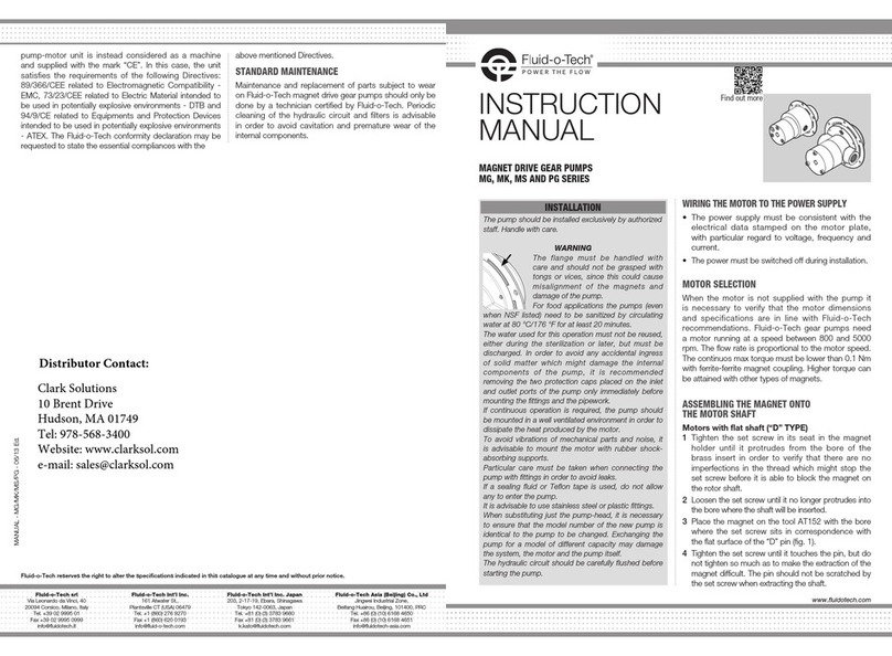
INSTRUCTION
MANUAL
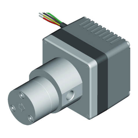
MAGNET DRIVE GEAR PUMPS
MG, MK, MS AND PG SERIES
www.fluidotech.com
The pump should be installed exclusively by authorized
staff. Handle with care.
WARNINGS
• The flange must be handled with care and
should not be grasped with tongs or vices,
since this could cause misalignment of the
magnets and damage of the pump.
• For food applications the pumps (even when
NSF listed) need to be sanitized by circulating
water at 80°C/ 176°F for at least 20 minutes.
• The magnetic coupling does not guarantee a defined value of
the discharge pressure. Should it be necessary to protect the
hydraulic circuit from any possible fluid hammers generated
by the pump, it is vital using a pump, equipped with a bypass
or a safety valve to be installed after the pump itself.
• Dedicated configurations are available if the operating outlet
pressure is in between 10bar/145psi and 15bar/ 217psi. In
case of higher outlet pressure, 15bar/217psi to 20bar/290psi,
please consult the factory.
• The hydraulic circuit should be carefully flushed before starting
the pump.
• The water used for this operation must not be reused, either
during the sterilization or later, but must be discharged.
•In order to avoid any accidental ingress of solid matter which
might damage the internal components of the pump, it is
recommended removing the two protection caps placed on
the inlet and outlet ports of the pump only immediately before
mounting the fittings and the pipework.
• If continuous operation is required, the pump should be mounted
in a well ventilated environment in order to dissipate the heat
produced by the motor.
• To avoid vibrations of mechanical parts and noise, it is advisable
to mount the motor with rubber shock-absorbing supports.
• Particular care must be taken when connecting the pump with
fittings in order to avoid leaks. If Teflon tape is used it is important
not to use too much of it (no more than 2 or 3 turns) to avoid
pieces of PTFE accidentally falling into the pump.
• Before tightening the fittings, hold the part of the pump body
close to the threaded holes. The leverage effects and mis-
manipulation, like the fittings fixation with the pump already
installed onto the motor, can cause components deformation,
leakages, malfunctioning.
• Do not use sealing fluid, as drops may fall into the pipes and
cause the pump block.
• It is advisable to use stainless steel or plastic fittings.
• When substituting just the pump-head, it is necessary to ensure that
the model number of the new pump is identical to the pump to be
changed. Exchanging the pump for a model of different capacity may
damage the system, the motor and the pump itself.
• For pumps equipped with relief valve the thread on the fittings
must not exceed 5 mm. Failure to observe such warning will result
on damage to the relief valve spring.
INSTALLATION
WIRING THE MOTOR TO THE POWER SUPPLY
• The power supply must be consistent with the
electrical data stamped on the motor plate, with
particular regard to voltage, frequency and current.
• The power must be switched off during installation.
MOTOR SELECTION
When the motor is not supplied with the pump it
is necessary to verify that the motor dimensions
and specifications are in line with Fluid-o-Tech
recommendations. Fluid-o-Tech gear pumps need
a motor running at a speed between 800 and 5000
rpm. The flow rate is proportional to the motor speed.
The continuos max torque must be lower than 0.1 Nm
with ferrite-ferrite magnet coupling. Higher torque can
be attained with other types of magnets.
ASSEMBLING THE MAGNET ONTO THE MOTOR SHAFT
Motors with flat shaft (“D” TYPE)
1Tighten the set screw in its seat in the magnet
holder until it protrudes from the bore of the brass
MG-MK-MS AND PG MANUAL en - 09/21 Ed.
Fluid-o-Tech reserves the right to alter the specifications indicated in this catalogue at any time and without prior notice.
Generally, avoid significant dust or other materials
deposits. The equipment to be installed must be
undamaged and must have been properly stored
before installation, in case of doubt, please consult
Fluid-o-Tech.
In case of overpressure in the system, equip the system
with an adequate safety valve (dimensions, performance,
standards, ...) with the certification of conformity for the
intended ATEX zone.
The bypass valve integrated in certain pump
configurations is NOT to be intended as a safety valve,
but as a simple relief valve for accidental overpressure.
In case the pressure or the temperature (ambient
and/or fluid) exceeded the limit, please consult
Fluid-o-Tech to repair the pump with the replacement of
damaged components and general functioning check.
Inlet and outlet lines should be designed properly for the
required performance conditions and should be executed
accordingly, please refer to the instruction manual. Issues
like cavitation, vapor lock and similar working conditions
must be avoided since they could cause severe problems
and lead to excessive vibrations and premature pump
failure. Lines must be internally cleaned and free of any
foreign particles.
For protection against potentially explosive atmospheres,
it is important that the area around the pump and the
pump itself are clean. During installation and maintenance
use non-sparking tools when working on the pump unit in
a potentially explosive atmosphere.
IGNITION HAZARD ASSESSMENT
IMPLEMENTED BY THE USER
Risks evaluation on the system should be implemented
by the user, according to specific usage and working
conditions, considering:
- analysis of the ignition hazards and their causes;
- frequency and duration of the ignition hazards;
- characteristics of the system, processes and their
interactions;
- entity of consequences.
Through ignition hazard assessment, the user defines
the areas and divides them into zones, with the proper
signals on the access points.
DISCLAIMER
Considerable effort has been made to avoid
inaccuracies and omissions in this manual, if you
should find an error or omission, please contact
Fluid-o-Tech. Fluid-o-Tech reserves the right to update
the design and the specifications of the products at any
time and without prior notice.
insert in order to verify that there are no imperfections
in the thread which might stop the set screw before it
is able to block the magnet on the rotor shaft.
2Loosen the set screw until it no longer protrudes into the
bore where the shaft will be inserted.
3Place the magnet on the tool AT152 with the bore
where the set screw sits in correspondence with the
flat surface of the “D” pin (fig. 1).
4Tighten the set screw until it touches the pin, but do
not tighten so much as to make the extraction of the
magnet difficult. The pin should not be scratched by the
set screw when extracting the shaft.
5Remove the magnet and place it on the motor shaft.
In this way the set screw, protruding slightly from the
internal diameter of the bore in the brass bushing,
prevents incorrect orientation of the magnet during
assembly onto the motor shaft.
6Place the unit vertically on tool AT 152/1 with the
magnet facing downwards in order to set the magnet
in the correct position (see fig. 2).
Tighten the set screw with a max. torque of 1.5 Nm.
Motors with shaft key seat and MGAS/MGAF series
driving magnets
1Tighten the set screw in its seat in the magnet holder
until it protrudes from the bore of the brass insert in
order to verify that there are no imperfections in the
thread which might stop the set screw before it is able
to block the magnet on the rotor shaft.
2Loosen the set screw until it no longer protrudes into
the bore where the shaft will be inserted.
3Ensure the shaft key is removed from its seat on the
motor shaft.
4Place the unit vertically on tool AT 152/1 with the
magnet facing downwards in order to set the magnet
in the correct position (see fig. 3). Tighten the set
screw with a max. torque of 1.5 Nm.
note:For dimensions of tool AT 152/1 refer to table 1.
OPERATING CONDITIONS
Ensure that the pump materials are compatible with
the pumped fluid. Fluid-o-Tech pumps are designed to
handle clean water at ambient temperature.
Any other fluid and/or operating condition need to be
tested and approved by the customer and verified by
Fluid-o-Tech. The maximum liquid temperature is 120
°C (248 °F). It is strongly recommended, especially for
the inlet, using a pipe with an inner diameter sufficient to
handle the pump’s capacity. This will avoid cavitation and
consequent failure of the pump. The discharge pressure
must not exceed 20bar/290psi in any event.
The piping on the discharge side should therefore be able
to handle a pressure of 20 bar (290 psi).*
It is also recommended installing a filter before the pump
capable of keeping out particles larger than 10 μm which
could cause fast wear of the internal components, and
with a surface area large enough not to cause hydraulic
losses in the circuit. It is also important to check
periodically the filter cartridge. In order to keep the filter
under control, it is advisable to install a vacuum gauge
after the filter. In case the vacuum increases more than
0.1 bar, the cartridge should be cleaned or changed.
For long pump life, the pumped fluid must not contain
solid particles. Although the magnet drive gear pumps
are self-priming, they should operate under wetted
conditions, as dry running will cause accelerated wear
of the internal components. A dirty filter or an insufficient
supply of water can cause cavitation and accelerated
wear of the internal components of the pump.
If the suction line is subject to low pressure or flow it
is recommended fitting a pressure/level switch before
the pump in order to switch the motor off when that
happens. It is also recommended to protect the system
from accidental overpressure with safety devices such
as a pressure relief valve or a pressure switch connected
to the motor. It is not advisable to install solenoid valves
in the circuit; however, if necessary, the soleinoid valve
should only be installed after the pump. Solenoid valves
installed before the pump should be avoided at all times.
The internal diameter should be appropriately sized for
the pump capacity. In order to avoid pressure spikes the
solenoid valve should only be operated after the pump
has stopped, allowing a few seconds to go by after the
motor has been switched off. If the pump is equipped
with a relief valve (bypass), the valve will act, in case of
accidental overpressure, to limit the pressure, by means
or recirculatinf the fluid internally.
The relief valve is not a flow regulator, and should
not be used as such. If used as a flow regulator, the
excess fluid will recirculate within the pump, through
the relief valve, and the pump may fail.
The maximum differential pressure should be at least
1 bar (14.5 psi) lower than the relief valve setting in
order to avoid fluid recirculation and therefore loss of
capacity and ultimately failure.
Due to magnetic coupling, the pump does not require a
mechanical seal to prevent leakage. This eliminates the
usual problems associated with the use of a mechanical
seal. The maximun pressure varies with pump model and
speed. As the differential pressure deacreses the flow
rate will increase.
Beyond the values specified in the charts on page 4 of
this leaflet where the performances outside the grey area
are attained with the rare earths magnet, the torque that
can be transmitted is limited by the magnet strenght, and
the coupling between the motor and the pump is not
guaranteed, therefore the pump might stop. The coupling
can be re-established simply by switching off the motor,
waiting until it is completely stopped, and then restarting
the motor again.
WARRANTY
Every new pump manufactured by Fluid-o-Tech is
guaranteed to be free of defects in workmanship and
material when leaving the factory for a period of 18 months
from the production date printed on pump label, plus a
period of 6 months to cover the warehouse and transit time,
or for a period of maximum 24 months from the purchasing
date to the first product use. In no event shall this period
exceed 24 months from date of original invoice.
Fluid-o-Tech will repair or replace at our discretion part or
all of the product not conforming to this warranty. Fluid-o-
Tech’s responsibility under this warranty is limited to the
repair or replacement of defective product returned to us
on an DDP basis, providing that our analysis discloses that
such part or parts were defective at the time of sale.
The warranty is not recognized if:
• The instructions on how to handle, install or operate
the pump are disregarded.
• The pump has been disassembled or modified by
anyone other than a Fluid-o-Tech (or authorized by
Fluid-o-Tech) engineer or repaired with non original
components.
• The pump gas been operated dry, under cavitation.
• Solid extraneous particles are found in the pump.
• Obvious signs of excess pressure are evident.
• The pump has been utilized for an application for
which it was not intended to be used where the
operating conditions and/or the pumped liquid were
incompatible with the pump itself and this application
has not been specifically approved by Fluid-o-Tech.
• In case of pumps equipped with a relief valve, when
Fig. 1
Tool pin reference plane
Fig. 2 - MGAF series driving magnets with “D” shaft
AT-152_1
Fig. 3 - MGAF series driving magnets with shaft key seat
AT-152_1
X
Tool AT-152_.. options (depending on pump series
and magnet type)
Pump series MG/MS MK
Magnet type MGAF MGAS MKAF MKAS
“X” dimension 3 3 3 6
(in mm)
Tool type AT-152_1 AT-152_2 AT-152_8
Tab. 1: Tool AT-152_..
All the components must be metallic and conductive
(adapter included). Proper earthing on the whole
equipment is required.
Pump operation involves the risk of producing an
electrostatic charge in flowing liquids. The user should
take measures according to IEC TS 60079-32-1. Only
liquids with a high conductivity (> 1000 pS/m) can be
used.
In order to prevent temperature increase, avoid working
with:
- closed outlet port;
- direct return of liquid from outlet to inlet side of the
pump.
INSTALLATION AND MAINTENANCE
Please refer to the instruction manual and follow the
instructions available for the installation (paragraph
“Assembling the magnet onto the motor shaft”) using the
tool AT-152_....
During the operation of assembling the magnet onto the
motor shaft, verify that noises and/or vibrations are not
present when the motor shaft rotates.
A dedicated tool is available: AT- 628_..., please refer to
the table below for the various configuration.
Remove the AT-628_... tool and assembly the pump,
verify again that noises and/or vibrations are not present
when the motor shaft rotates. Perform a periodical check
of the alignment of the pump and the external magnet.
Perform a periodical check of the pump performance
(every 1000 h of operation), if the decrease in
performances is higher than 20% it is needed to replace
the pump. Proper earthing of the whole equipment
(motor + adapter + pump) is required. Earthing terminals
should be provided on the motor, if not possible, apply
earthing connection on another component of the group.
Verify periodically the proper earthing of the whole group.
The adapter covers rotating parts such as external
magnet and motor shaft, all the open holes in the adapter
must be plugged.
Verify the chemical and thermal compatibility of the fluid
with the pump materials. Periodically check that no
leakages are present.
Periodically clean the equipment, also the internal
part of the adapter/coupling, the pump should then
be accessible for maintenance and inspection.
MKAS
MKAF
MGAF / MGAS
the operating pressure has been less than 1 bar below
the relief valve setting.
• Normal wear and tear is not covered by the present
warranty
The adjustment or replacement of defective parts made
under this warranty will not extend the original warranty
period. The Purchaser/User is responsible for the
disposal or recycling of the product at end of its use or
lifetime. For more information on proper disposal method,
please contact Fluid-o-Tech Customer Care.
CERTIFICATIONS
NSF listed pumps available for drinkable liquids. For the
model details, please refer to the official NSF website
(direct link available on www.fluidotech.it)
The pump itself, without the motor, is not to be
considered as a machine, but only a component,
therefore the mark “CE” is not applicable.
When the pump is assembled with a motor, the complete
pump-motor unit is instead considered as a machine and
supplied with the mark “CE”. Please refer to Fluid-o-Tech
declaration of conformity, which may be requested to
state the essential compliances with the Directives.
STANDARD MAINTENANCE
Maintenance and replacement of parts subject to wear
on Fluid-o-Tech magnet drive gear pumps should only be
done by a technician certified by Fluid-o-Tech. Periodic
cleaning of the hydraulic circuit and filters is advisable
in order to avoid cavitation and premature wear of the
internal components.
ATEX CERTIFICATIONS FOR
MG, MK AND MS PUMP SERIES
GENERAL
This manual contains important and useful information
on protection against the risks in potentially explosive
atmospheres in accordance with EC directive 2014/34/
EU. All relevant instructions about installation, operation
and maintenance of the pump are available in the
separate pump’s instruction manual.
For protection against the risks in potentially
explosive atmospheres it is imperative that the pump
must be protected from all unauthorized operation
and unnecessary wear. Explosive gas mixtures or
concentrations of dust, in conjunction with hot and
moving parts on pump and on the driving unit, can
lead to severe or fatal personal injuries. Installation,
connection, start-up and maintenance must only be
performed by qualified technicians taking into account
the instructions reported in this manual together with all
other instructions for the installed equipment and system.
Specific regulations and requirements for the complete
system must be considered (current valid national and
regional regulations).
Since the maximum surface temperature depends mainly
on the operating conditions given by the heated fluid
in the pump, a single temperature class or maximum
surface temperature cannot be determined by the
manufacturer.
The temperature class with the maximum allowed fluid
temperature (fluids up to 120°C) is T3 (< 200°C), the
temperature class can be lowered to T4 (< 135°C) but
in this case the fluid temperature must not exceed 70°C.
Ambient temperature range: -20/+40°C.
In order to use the pump in ATEX Zone
1, it is needed to implement an ignition
protection system “b” monitoring the
temperature class required T3 (< 200°C) or
T4 (< 135°C) depending on the maximum
fluid temperature selected (120°C or 70°C,
respectively).
Specified temperature limits might be exceeded in case
the pump is operated outside the specified operating
range (temperature and pressure) and in unauthorized
modes. In addition to the temperature monitoring
device, a pressure monitoring device is mandatory if the
limits cannot be observed under all possible operating
conditions. A minimum sufficient flow through the pump
must be assured in order to remove the heat generated
by the pump operation.
Verify that heated air from other units close to the pump
does not affect the ambient temperature around the
pump (maximum ambient temperature is 40°C).
Pump must not run in dry conditions, internals must be
filled completely with, and lubricated by the liquid that
will be used during operation (including start-up, priming
and shut-off). Equip the fluid tank with a sensor level and
be sure that hydraulic connections are made at state of
the art.
Pump must always run with fluids in liquid phase.
The intended use of the equipment is:
- in an atmospheric pressure environment;
- in a fixed installation (it is not considered as handheld
equipment or equipment carried on the person).
Do not use abrasive fluids with the pump.
Only equipment with certification of conformity for the
intended ATEX zone must be used.
Maximum fluid temperature Temperature class
120°C T3 (< 200°C)
70°C T4 (< 135°C)
Tool AT-628_... options (depending on pump series and
magnet type)
Pump series MG/MS MK
Magnet type MGAF MGAS MKAF MKAS
Tool type AT-628_4 AT-628_9
Fluid-o-Tech Int’l Inc.
161 Atwater St.,
Plantsville CT (USA) 06479
Tel. +1 (860) 276 9270
Fax +1 (860) 620 0193
[email protected]
Fluid-o-Tech Int’l Inc. Japan
2nd Floor, 4-3-8, Espoir Todoroki,
Todoroki, Setagaya, Tokyo 158-0082
Tel. +81 (0) (3) 6432 1812
Fax +81 (0) (3) 6432 1813
[email protected]
Fluid-o-Tech Asia (Shanghai) Co., Ltd.
2/F, Factory building 6 (1), No. 258, Zhijiang Road,
Fengxian District, Shanghai City, Z.P.: 201499 China
Tel. +86 (021) 67100 838
Fax +86 (021) 67100 605
[email protected]
Fluid-o-Tech srl
Via Leonardo da Vinci, 40
20094 Corsico, Milano, Italy
Tel. +39 02 9995 01
Fax +39 02 9995 0999
[email protected]
INSTRUCTION
MANUAL
MAGNET DRIVE GEAR PUMPS
MG, MK, MS AND PG SERIES
www.fluidotech.com
The pump should be installed exclusively by authorized
staff. Handle with care.
WARNINGS
• The flange must be handled with care and
should not be grasped with tongs or vices,
since this could cause misalignment of the
magnets and damage of the pump.
• For food applications the pumps (even when
NSF listed) need to be sanitized by circulating
water at 80°C/ 176°F for at least 20 minutes.
• The magnetic coupling does not guarantee a defined value of
the discharge pressure. Should it be necessary to protect the
hydraulic circuit from any possible fluid hammers generated
by the pump, it is vital using a pump, equipped with a bypass
or a safety valve to be installed after the pump itself.
• Dedicated configurations are available if the operating outlet
pressure is in between 10bar/145psi and 15bar/ 217psi. In
case of higher outlet pressure, 15bar/217psi to 20bar/290psi,
please consult the factory.
• The hydraulic circuit should be carefully flushed before starting
the pump.
• The water used for this operation must not be reused, either
during the sterilization or later, but must be discharged.
•In order to avoid any accidental ingress of solid matter which
might damage the internal components of the pump, it is
recommended removing the two protection caps placed on
the inlet and outlet ports of the pump only immediately before
mounting the fittings and the pipework.
• If continuous operation is required, the pump should be mounted
in a well ventilated environment in order to dissipate the heat
produced by the motor.
• To avoid vibrations of mechanical parts and noise, it is advisable
to mount the motor with rubber shock-absorbing supports.
• Particular care must be taken when connecting the pump with
fittings in order to avoid leaks. If Teflon tape is used it is important
not to use too much of it (no more than 2 or 3 turns) to avoid
pieces of PTFE accidentally falling into the pump.
• Before tightening the fittings, hold the part of the pump body
close to the threaded holes. The leverage effects and mis-
manipulation, like the fittings fixation with the pump already
installed onto the motor, can cause components deformation,
leakages, malfunctioning.
• Do not use sealing fluid, as drops may fall into the pipes and
cause the pump block.
• It is advisable to use stainless steel or plastic fittings.
• When substituting just the pump-head, it is necessary to ensure that
the model number of the new pump is identical to the pump to be
changed. Exchanging the pump for a model of different capacity may
damage the system, the motor and the pump itself.
• For pumps equipped with relief valve the thread on the fittings
must not exceed 5 mm. Failure to observe such warning will result
on damage to the relief valve spring.
INSTALLATION
WIRING THE MOTOR TO THE POWER SUPPLY
• The power supply must be consistent with the
electrical data stamped on the motor plate, with
particular regard to voltage, frequency and current.
• The power must be switched off during installation.
MOTOR SELECTION
When the motor is not supplied with the pump it
is necessary to verify that the motor dimensions
and specifications are in line with Fluid-o-Tech
recommendations. Fluid-o-Tech gear pumps need
a motor running at a speed between 800 and 5000
rpm. The flow rate is proportional to the motor speed.
The continuos max torque must be lower than 0.1 Nm
with ferrite-ferrite magnet coupling. Higher torque can
be attained with other types of magnets.
ASSEMBLING THE MAGNET ONTO THE MOTOR SHAFT
Motors with flat shaft (“D” TYPE)
1Tighten the set screw in its seat in the magnet
holder until it protrudes from the bore of the brass
MG-MK-MS AND PG MANUAL en - 09/21 Ed.
Fluid-o-Tech reserves the right to alter the specifications indicated in this catalogue at any time and without prior notice.
Generally, avoid significant dust or other materials
deposits. The equipment to be installed must be
undamaged and must have been properly stored
before installation, in case of doubt, please consult
Fluid-o-Tech.
In case of overpressure in the system, equip the system
with an adequate safety valve (dimensions, performance,
standards, ...) with the certification of conformity for the
intended ATEX zone.
The bypass valve integrated in certain pump
configurations is NOT to be intended as a safety valve,
but as a simple relief valve for accidental overpressure.
In case the pressure or the temperature (ambient
and/or fluid) exceeded the limit, please consult
Fluid-o-Tech to repair the pump with the replacement of
damaged components and general functioning check.
Inlet and outlet lines should be designed properly for the
required performance conditions and should be executed
accordingly, please refer to the instruction manual. Issues
like cavitation, vapor lock and similar working conditions
must be avoided since they could cause severe problems
and lead to excessive vibrations and premature pump
failure. Lines must be internally cleaned and free of any
foreign particles.
For protection against potentially explosive atmospheres,
it is important that the area around the pump and the
pump itself are clean. During installation and maintenance
use non-sparking tools when working on the pump unit in
a potentially explosive atmosphere.
IGNITION HAZARD ASSESSMENT
IMPLEMENTED BY THE USER
Risks evaluation on the system should be implemented
by the user, according to specific usage and working
conditions, considering:
- analysis of the ignition hazards and their causes;
- frequency and duration of the ignition hazards;
- characteristics of the system, processes and their
interactions;
- entity of consequences.
Through ignition hazard assessment, the user defines
the areas and divides them into zones, with the proper
signals on the access points.
DISCLAIMER
Considerable effort has been made to avoid
inaccuracies and omissions in this manual, if you
should find an error or omission, please contact
Fluid-o-Tech. Fluid-o-Tech reserves the right to update
the design and the specifications of the products at any
time and without prior notice.

This manual suits for next models

3

Other fluid-o-tech Water Pump manuals

fluid-o-tech MG 200 Series User manual

fluid-o-tech

fluid-o-tech MG 200 Series User manual

fluid-o-tech FG Series User manual

fluid-o-tech

fluid-o-tech FG Series User manual

fluid-o-tech TMFR User manual

fluid-o-tech

fluid-o-tech TMFR User manual

fluid-o-tech ROTOFLOW User manual

fluid-o-tech

fluid-o-tech ROTOFLOW User manual

fluid-o-tech MONO Series User manual

fluid-o-tech

fluid-o-tech MONO Series User manual

fluid-o-tech DGD PRO Series User manual

fluid-o-tech

fluid-o-tech DGD PRO Series User manual

fluid-o-tech TP30 Series User manual

fluid-o-tech

fluid-o-tech TP30 Series User manual

fluid-o-tech DGD Series User manual

fluid-o-tech

fluid-o-tech DGD Series User manual

fluid-o-tech MK series User manual

fluid-o-tech

fluid-o-tech MK series User manual

Popular Water Pump manuals by other brands

Goulds Pumps 3935 Installation, operation and maintenance instructions

Goulds Pumps

Goulds Pumps 3935 Installation, operation and maintenance instructions

SprayTECH ED655 Plus owner's manual

SprayTECH

SprayTECH ED655 Plus owner's manual

Graco Endura-Flo 4D150 Instructions - parts

Graco

Graco Endura-Flo 4D150 Instructions - parts

Adam Pumps G FLOW TRANSLATION OF ORIGINAL INSTRUCTIONS

Adam Pumps

Adam Pumps G FLOW TRANSLATION OF ORIGINAL INSTRUCTIONS

Xylem Goulds GB Series Installation, operation and maintenance instructions

Xylem

Xylem Goulds GB Series Installation, operation and maintenance instructions

ITT Bornemann SLH-4G operating instructions

ITT

ITT Bornemann SLH-4G operating instructions

EBARA 3D Operating and maintenance manual

EBARA

EBARA 3D Operating and maintenance manual

Lowara e-HM series Installation, operation and maintenance

Lowara

Lowara e-HM series Installation, operation and maintenance

DLS DLS-Pump 2071 user manual

DLS

DLS DLS-Pump 2071 user manual

Graco Series A instructions

Graco

Graco Series A instructions

Maxspect Jump Series owner's manual

Maxspect

Maxspect Jump Series owner's manual

Denso first time fit instructions

Denso

Denso first time fit instructions

GilAir Plus PN 360-0132-01 quick start guide

GilAir Plus

GilAir Plus PN 360-0132-01 quick start guide

WORMS ACCESS j 8-25 Instructions for use

WORMS

WORMS ACCESS j 8-25 Instructions for use

GORMAN-RUPP PUMPS T SERIES Installation, operation, and maintenance manual with parts list

GORMAN-RUPP PUMPS

GORMAN-RUPP PUMPS T SERIES Installation, operation, and maintenance manual with parts list

Aqua HC 200 Programming instructions

Aqua

Aqua HC 200 Programming instructions

Coleman QUICKPUMP user manual

Coleman

Coleman QUICKPUMP user manual

Hi-Force HPP Series Operating instructions manual

Hi-Force

Hi-Force HPP Series Operating instructions manual

manuals.online logo
manuals.online logoBrands
  • About & Mission
  • Contact us
  • Privacy Policy
  • Terms and Conditions

Copyright 2025 Manuals.Online. All Rights Reserved.