manuals.online logo
Brands
  1. Home
  2. •
  3. Brands
  4. •
  5. fluid-o-tech
  6. •
  7. Water Pump
  8. •
  9. fluid-o-tech MK series User manual

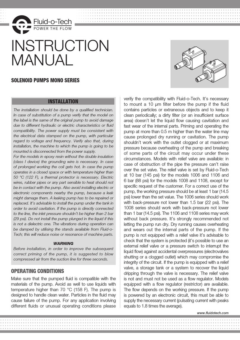
fluid-o-tech MK series User manual

www.fluidotech.com
INSTRUCTION
MANUAL
MANUAL - MG/MK/MS/PG - 06/13 Ed.
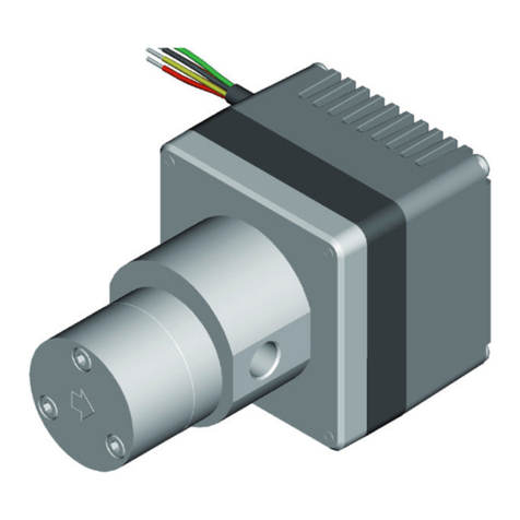
MAGNET DRIVE GEAR PUMPS
MG, MK, MS AND PG SERIES
The pump should be installed exclusively by authorized
staff. Handle with care.
WARNING
The flange must be handled with
care and should not be grasped with
tongs or vices, since this could cause
misalignment of the magnets and
damage of the pump.
For food applications the pumps (even
when NSF listed) need to be sanitized by circulating
water at 80 °C/176 °F for at least 20 minutes.
The water used for this operation must not be reused,
either during the sterilization or later, but must be
discharged. In order to avoid any accidental ingress
of solid matter which might damage the internal
components of the pump, it is recommended
removing the two protection caps placed on the inlet
and outlet ports of the pump only immediately before
mounting the fittings and the pipework.
If continuous operation is required, the pump should
be mounted in a well ventilated environment in order to
dissipate the heat produced by the motor.
To avoid vibrations of mechanical parts and noise, it
is advisable to mount the motor with rubber shock-
absorbing supports.
Particular care must be taken when connecting the
pump with fittings in order to avoid leaks.
If a sealing fluid or Teflon tape is used, do not allow
any to enter the pump.
It is advisable to use stainless steel or plastic fittings.
When substituting just the pump-head, it is necessary
to ensure that the model number of the new pump is
identical to the pump to be changed. Exchanging the
pump for a model of different capacity may damage
the system, the motor and the pump itself.
The hydraulic circuit should be carefully flushed before
starting the pump.
WIRING THE MOTOR TO THE POWER SUPPLY
• The power supply must be consistent with the
electrical data stamped on the motor plate,
with particular regard to voltage, frequency and
current.
• Thepowermustbeswitchedoffduringinstallation.
MOTOR SELECTION
When the motor is not supplied with the pump it
is necessary to verify that the motor dimensions
and specifications are in line with Fluid-o-Tech
recommendations. Fluid-o-Tech gear pumps need
a motor running at a speed between 800 and 5000
rpm.Theflowrateisproportionaltothemotorspeed.
Thecontinuosmaxtorquemustbelowerthan0.1Nm
withferrite-ferritemagnetcoupling.Highertorquecan
beattainedwithothertypesofmagnets.
ASSEMBLING THE MAGNET ONTO
THE MOTOR SHAFT
Motors with flat shaft (“D” TYPE)
1 Tighten the set screw in its seat in the magnet
holder until it protrudes from the bore of the
brass insert in order to verify that there are no
imperfections in the thread which might stop the
setscrew beforeit isable toblock themagnet on
therotorshaft.
2Loosenthesetscrewuntilitnolongerprotrudesinto
theborewheretheshaftwillbeinserted.
3 Placethemagneton thetoolAT152with thebore
where the set screw sits in correspondence with
theflatsurfaceofthe“D”pin(fig.1).
4Tightenthesetscrewuntilittouchesthepin,butdo
nottightensomuchastomaketheextractionofthe
magnetdifficult.Thepinshouldnotbescratchedby
thesetscrewwhenextractingtheshaft.
pump-motor unit is instead considered as a machine
and supplied with the mark “CE”. In this case, the unit
satisfies the requirements of the following Directives:
89/366/CEE related to Electromagnetic Compatibility -
EMC,73/23/CEE related toElectric Material intendedto
beusedinpotentiallyexplosiveenvironments- DTB and
94/9/CE related to Equipments and Protection Devices
intendedtobeusedinpotentiallyexplosiveenvironments
-ATEX.The Fluid-o-Tech conformitydeclarationmay be
requestedtostatetheessentialcomplianceswiththe
abovementionedDirectives.
STANDARD MAINTENANCE
Maintenance and replacement of parts subject to wear
onFluid-o-Techmagnetdrivegearpumpsshouldonlybe
done by a technician certified by Fluid-o-Tech. Periodic
cleaning of the hydraulic circuit and filters is advisable
in order to avoid cavitation and premature wear of the
internalcomponents.
Fluid-o-Tech Int’l Inc.
161AtwaterSt.,
PlantsvilleCT(USA)06479
Tel.+1(860)2769270
Fax+1(860)6200193
[email protected]
Fluid-o-Tech Int’l Inc. Japan
203,2-17-19,Ebara,Shinagawa
Tokyo142-0063,Japan
Tel.+81(0)(3)37839660
Fax+81(0)(3)37839661
[email protected]
Fluid-o-Tech Asia (Beijing) Co., Ltd
JingweiIndustrialZone,
BeifangHuairou,Beijing,101400,PRC
Tel.+86(0)(10)61684650
Fax+86(0)(10)61684651
[email protected]
Fluid-o-Tech srl
ViaLeonardodaVinci,40
20094Corsico,Milano,Italy
Tel.+3902999501
Fax+390299950999
[email protected]
Fluid-o-Tech reserves the right to alter the specifications indicated in this catalogue at any time and without prior notice.
INSTALLATION
Find out more
Clark Solutions
10 Brent Drive
Hudson, MA 01749
Tel: 978-568-3400
Website: www.clarksol.com
e-mail: [email protected]
Distributor Contact:
5 Remove the magnet and place it on the motor shaft.
In this way the set screw, protruding slightly from the
internal diameter of the bore in the brass bushing,
prevents incorrect orientation of the magnet during
assemblyontothemotorshaft.
6 Place the unit vertically on tool AT 152/1 with the
magnetfacing downwardsin order toset themagnet
inthecorrectposition(seefig.2).
 Tightenthesetscrewwithamax.torqueof1.5Nm.
Motors with shaft key seat and MGAS/MGAF series
driving magnets
1 Tightentheset screwin its seatin the magnetholder
until it protrudes from the bore of the brass insert in
order to verify that there are no imperfections in the
threadwhichmightstopthesetscrewbeforeitisable
toblockthemagnetontherotorshaft.
2 Loosen the set screw until it no longer protrudes into
theborewheretheshaftwillbeinserted.
3 Ensure the shaft key is removed from its seat on the
motorshaft.
4 Place the unit vertically on tool AT 152/1 with the
magnetfacing downwardsin order toset themagnet
in the correct position (see fig. 3). Tighten the set
screwwithamax.torqueof1.5Nm.
note:
For dimensions of tool AT 152/1 refer to table 1.
OPERATING CONDITIONS
Ensure that the pump materials are compatible with
the pumped fluid. Fluid-o-Tech pumps are designed to
handlecleanwateratambienttemperature.
Any other fluid and/or operating condition need to be
tested and approved by the customer and verified by
Fluid-o-Tech. The maximum liquid temperature is 120
°C (248 °F). It is strongly recommended, especially for
theinlet,usingapipewithaninnerdiametersufficientto
handlethepump’scapacity.Thiswillavoidcavitationand
consequentfailure ofthe pump.The dischargepressure
mustnotexceed20bar/290psiinanyevent.
Thepipingonthedischargesideshouldthereforebeable
tohandleapressureof20bar(290psi).
Itisalsorecommendedinstallingafilterbeforethepump
capableofkeepingoutparticleslargerthan10μmwhich
could cause fast wear of the internal components, and
witha surface arealarge enough not to cause hydraulic
losses in the circuit. It is also important to check
periodically the filter cartridge. In order to keep the filter
under control, it is advisable to install a vacuum gauge
after the filter. In case the vacuum increases more than
0.1bar,thecartridgeshouldbecleanedorchanged.
For long pump life, the pumped fluid must not contain
solid particles. Although the magnet drive gear pumps
are self-priming, they should operate under wetted
conditions, as dry running will cause accelerated wear
oftheinternalcomponents.Adirtyfilteroraninsufficient
supply of water can cause cavitation and accelerated
wearoftheinternalcomponentsofthepump.
If the suction line is subject to low pressure or flow it
is recommended fitting a pressure/level switch before
the pump in order to switch the motor off when that
happens. It is also recommended to protect the system
from accidental overpressure with safety devices such
asapressurereliefvalveorapressureswitchconnected
tothemotor. It isnotadvisable to installsolenoidvalves
in the circuit; however, if necessary, the soleinoid valve
should only be installed after the pump. Solenoid valves
installedbeforethepumpshouldbeavoidedatalltimes.
The internal diameter should be appropriately sized for
thepumpcapacity.Inordertoavoidpressurespikesthe
solenoid valve should only be operated after the pump
has stopped, allowing a few seconds to go by after the
motor has been switched off. If the pump is equipped
with a relief valve (bypass), the valve will act, in case of
accidentaloverpressure, to limit the pressure,by means
orrecirculatinfthefluidinternally.
The relief valve is not a flow regulator, and should
notbeused as such.Ifused as aflowregulator, the
excess fluid will recirculate within the pump, through
thereliefvalve,andthepumpmayfail.
Themaximumdifferential pressure shouldbeat least
1 bar (14.5 psi) lower than the relief valve setting in
ordertoavoid fluid recirculationandtherefore lossof
capacityandultimatelyfailure.
Dueto magneticcoupling, thepump doesnot requirea
mechanical seal to prevent leakage. This eliminates the
usualproblemsassociated withtheuse ofa mechanical
seal. The maximun pressure varies with pump model
and speed. As the differential pressure deacreses the
flowratewillincrease.Beyondthevaluesspecifiedinthe
charts on page 4 of this leaflet where the performances
outside the grey area are attained with the rare earths
magnet, the torque that can be transmitted is limited
by the magnet strenght, and the coupling between the
motor and the pump is not guaranteed, therefore the
pump might stop. The coupling can be re-established
simply by switching off the motor, waiting until it is
completelystopped,andthenrestartingthemotoragain.
WARRANTY
Every new pump manufactured by Fluid-o-Tech is
guaranteed to be free of defects in workmanship and
materialwhenleavingthefactoryforaperiodof18months
from the production date printed on pump label, plus a
periodof6monthstocoverthewarehouseandtransittime,
orforaperiodofmaximum24monthsfromthepurchasing
date to the first product use. In no event shall this period
exceed24monthsfromdateoforiginalinvoice.
Fluid-o-Tech will repair or replace at our discretion part or
all ofthe productnotconforming tothis warranty.Fluid-o-
Tech’s responsibility under this warranty is limited to the
repair or replacement of defective product returned to us
onanDDPbasis,providingthatouranalysisdisclosesthat
suchpartorpartsweredefectiveatthetimeofsale.
Thewarrantyisnotrecognizedif:
• The instructions on how to handle, install or operate
thepumparedisregarded.
• The pump has been disassembled or modified by
anyone other than a Fluid-o-Tech (or authorized by
Fluid-o-Tech) engineer or repaired with non original
components.
• Thepumpgasbeenoperateddry,undercavitation.
• Solidextraneousparticlesarefoundinthepump.
• Obvioussignsofexcesspressureareevident.
• The pump has been utilized for an application for
which it was not intended to be used where the
operating conditions and/or the pumped liquid were
incompatible with the pump itself and this application
hasnotbeenspecificallyapprovedbyFluid-o-Tech.
• In case of pumps equipped with a relief valve, when
theoperatingpressurehasbeenlessthan1barbelow
thereliefvalvesetting.
• Normal wear and tear is not covered by the present
warranty
The adjustment or replacement of defective parts made
under this warranty will not extend the original warranty
period.
CERTIFICATIONS
NSFlistedpumpsavailablefordrinkableliquids.Forthe
modeldetails,pleaserefertotheofficialNSFwebsite
(directlinkavailableonwww.fluidotech.it)
The pump itself, without the motor, is not to be
considered as a machine, but only a component,
thereforethemark“CE”isnotapplicable.
Whenthepumpisassembledwithamotor,thecomplete
Fig. 1
Tool pin reference plane
Fig. 2 - MGAF series driving magnets with “D” shaft
AT-152_1
Fig. 3 - MGAF series driving magnets with shaft key seat
AT-152_1
X
Tool AT-152_.. options (depending on pump series
and magnet type)
Pump series MG/MS MK
Magnet type MGAF MGAS MKAF MKAS
“X” dimension 3 3 3 6
(in mm)
Tool type AT-152_1 AT-152_2 AT-152_8
Tab. 1: Tool AT-152_..

This manual suits for next models

3

Other fluid-o-tech Water Pump manuals

fluid-o-tech DGD Series User manual

fluid-o-tech

fluid-o-tech DGD Series User manual

fluid-o-tech DGD PRO Series User manual

fluid-o-tech

fluid-o-tech DGD PRO Series User manual

fluid-o-tech ROTOFLOW User manual

fluid-o-tech

fluid-o-tech ROTOFLOW User manual

fluid-o-tech MG Series User manual

fluid-o-tech

fluid-o-tech MG Series User manual

fluid-o-tech MONO Series User manual

fluid-o-tech

fluid-o-tech MONO Series User manual

fluid-o-tech TMFR User manual

fluid-o-tech

fluid-o-tech TMFR User manual

fluid-o-tech MG 200 Series User manual

fluid-o-tech

fluid-o-tech MG 200 Series User manual

fluid-o-tech TP30 Series User manual

fluid-o-tech

fluid-o-tech TP30 Series User manual

fluid-o-tech FG Series User manual

fluid-o-tech

fluid-o-tech FG Series User manual

Popular Water Pump manuals by other brands

DAYLIFF DS Installation & operating manual

DAYLIFF

DAYLIFF DS Installation & operating manual

Lafferty 920118 Installation & operation instructions

Lafferty

Lafferty 920118 Installation & operation instructions

Flux F 550 S Series Original main operating instructions

Flux

Flux F 550 S Series Original main operating instructions

Gormann-Rupp Pumps 6500 Series Installation, operation and maintenance manual

Gormann-Rupp Pumps

Gormann-Rupp Pumps 6500 Series Installation, operation and maintenance manual

POMPE CUCCHI MX Series Operating and maintenance manual

POMPE CUCCHI

POMPE CUCCHI MX Series Operating and maintenance manual

Barmesa Pumps BVL Series Installation, operation & maintenance manual

Barmesa Pumps

Barmesa Pumps BVL Series Installation, operation & maintenance manual

Goulds Prime Line SP SPH130 Installation, operation and maintenance instructions

Goulds

Goulds Prime Line SP SPH130 Installation, operation and maintenance instructions

IMI PNEUMATEX Transfero TVI Connect 19.1 H Install

IMI PNEUMATEX

IMI PNEUMATEX Transfero TVI Connect 19.1 H Install

Hozelock FLOWMAX 7500 manual

Hozelock

Hozelock FLOWMAX 7500 manual

Grundfos DMX Series Installation and operating instructions

Grundfos

Grundfos DMX Series Installation and operating instructions

Corken Z Series Installation, operation & maintenance manual

Corken

Corken Z Series Installation, operation & maintenance manual

Graco 205394 Instructions-parts list

Graco

Graco 205394 Instructions-parts list

Intex Krystal Clear 604 owner's manual

Intex

Intex Krystal Clear 604 owner's manual

Lincoln 9917 Installation and maintenance guide

Lincoln

Lincoln 9917 Installation and maintenance guide

Pulsafeeder GLM1 Installation operation & maintenance

Pulsafeeder

Pulsafeeder GLM1 Installation operation & maintenance

Waterous CM Series OVERHAUL INSTRUCTIONS

Waterous

Waterous CM Series OVERHAUL INSTRUCTIONS

BE SP-500TD user manual

BE

BE SP-500TD user manual

Warren rupp SandPIPER EB3-M Service & operating manual

Warren rupp

Warren rupp SandPIPER EB3-M Service & operating manual

manuals.online logo
manuals.online logoBrands
  • About & Mission
  • Contact us
  • Privacy Policy
  • Terms and Conditions

Copyright 2025 Manuals.Online. All Rights Reserved.