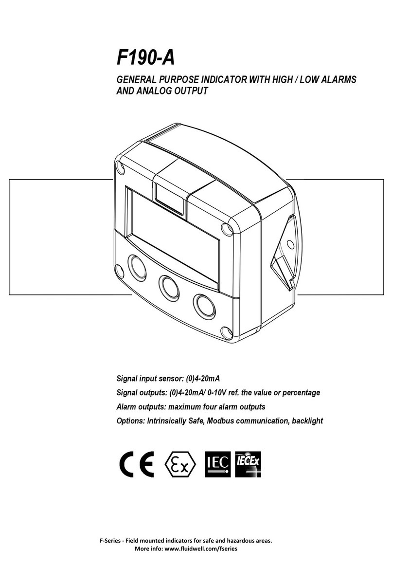
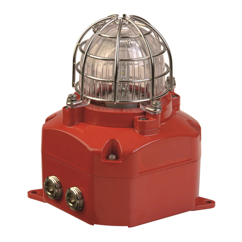
Fluidwell F1-A-PD-OS Series User manual

F1xx-A-PD-OS
INDICATORS WITH ANALOG SENSOR INPUT
WITH HIGH / LOW ALARMS
ADDENDUM / INSTALLATION GUIDE
FOR MODELS F113-A, F170-A AND F173-A
FOR TYPE PD-OS:
- 4 MECHANICAL RELAY OUTPUTS
F-Series - Field mounted indicators for safe and hazardous areas.
More info: www.fluidwell.com/fseries.

FW_F1xxAOS_v1702_03_EN (addendum).docx
Page 2
SAFETY INSTRUCTIONS
▪Any responsibility is lapsed if the instructions and procedures as described in this
manual are not followed.
▪LIFE SUPPORT APPLICATIONS: The F1xx-A is not designed for use in life support
appliances, devices, or systems where malfunction of the product can reasonably be
expected to result in a personal injury. Customers using or selling these products for
use in such applications do so at their own risk and agree to fully indemnify the
manufacturer and supplier for any damages resulting from such improper use or sale.
▪Electro static discharge does inflict irreparable damage to electronics! Before installing
or opening the unit, the installer has to discharge himself by touching a well-grounded
object.
▪This unit must be installed in accordance with the EMC guidelines (Electro Magnetic
Compatibility).
▪Do connect a proper grounding to the metal enclosure as indicated if the F1xx-A has an
incoming power line which carries a 115-230V AC. The Protective Earth (PE) wire may
never be disconnected or removed.
▪Intrinsic safe applications: follow the instructions as mentioned in Chapter 5 and consult
“Fluidwell F1..-..-XI - Documentation for Intrinsic safety”.
DISPOSAL OF ELECTRONIC WASTE
•The WEEE Directive requires the recycling of disposed electrical and electronic equipment in the
European Union. When the WEEE Directive does not apply to your region, we support its policy
and ask you to be aware on how to dispose of this product.
•The crossed out wheelie bin symbol as illustrated and found on our products tells that this
product shall not be disposed of into the general waste system or into a landfill.
•At the end of its life, equipment shall be disposed of according to the local regulations regarding
waste of the electrical and the electronic equipment.
•Please contact your local dealer, national distributor or the manufacturer’s Technical helpdesk for
information on the product disposal.
SAFETY RULES AND PRECAUTIONARY MEASURES
▪The manufacturer accepts no responsibility whatsoever if the following safety rules and
precautions instructions and the procedures as described in this manual are not followed.
▪Modifications of the F1xx-A implemented without preceding written consent from the
manufacturer, will result in the immediate termination of product liability and warranty period.
▪Mounting, electrical installation, start-up and maintenance of this device may only be carried out
by trained persons authorized by the operator of the facility. Persons must read and understand
this manual before carrying out its instructions.
▪This device may only be operated by persons who are authorized and trained by the operator of
the facility. All instructions in this manual are to be observed.
▪Check the mains voltage and information on the manufacturer's plate before installing the unit.
▪Check all connections, settings and technical specifications of the various peripheral devices
with the F1xx-A supplied.
▪Open the enclosure only if all leads are free of potential.
▪Never touch the electronic components (ESD sensitivity).
▪Never expose the system to heavier conditions than allowed according the classification of the
enclosure (see manufacture's plate and chapter 4).
▪If the operator detects errors or dangers, or disagrees with the safety precautions taken, then
inform the owner or principal responsible.
▪The local labor and safety laws and regulations must be adhered to.

FW_F1xxAOS_v1702_03_EN (addendum).docx
Page 3
ABOUT THE MANUAL
This manual is an addendum to the standard user manual ‘FW_F1xx-A_vxxxx_xx_EN’that is also
supplied with the F1xx-A-PD-OS flow rate monitor / totalizer and is suitable for the Level
indicators / monitors, models F170-A and F173-A and the Flowrate / Totalizer indicator / monitor,
model F113-A..
This addendum describes the terminal connections and configurations that are specific for type
PD-OS (4 mechanical relay outputs) and replaces chapter 4 of the standard user manual.
For all other types of supply (PM, PF, PD, PX) in combination with types OA, OT and OR, please
consult chapter 4 of the standard user manual ‘FW_F1xx-A_vxxxx_xx_EN’for your model. For
additional information, please contact your supplier.
A hazardous situation may occur if the F1xx-A is not used for the purpose it was designed for
or is used incorrectly. Please carefully note the information in this manual indicated by the
pictograms:
A "warning !" indicates actions or procedures which, if not performed correctly, may lead to
personal injury, a safety hazard or damage of the F1xx-A or connected instruments.
A "caution !" indicates actions or procedures which, if not performed correctly, may lead to
personal injury or incorrect functioning of the F1xx-A or connected instruments.
A "note !" indicates actions or procedures which, if not performed correctly, may indirectly
affect operation or may lead to an instrument response which is not planned.
WARRANTY AND TECHNICAL SUPPORT
For warranty and technical support for your Fluidwell products,
visit our internet site www.fluidwell.com or contact us at support@fluidwell.com.
Hardware version : 03.01.xx
Software version : 03.04.xx (F113-A) and 03.05.xx (F17x-A)
Manual : FW_F1xxAOS_v1702_03_EN (addendum).docx
© Copyright 2019 : Fluidwell B.V. - the Netherlands
Information in this manual is subject to change without prior notice. The
manufacturer is not responsible for mistakes in this material or for incidental
damage caused as a direct or indirect result of the delivery, performance or
use of this material.
© All rights reserved. No parts of this publication may be reproduced or used
in any form or by any means without written permission of your supplier.

FW_F1xxAOS_v1702_03_EN (addendum).docx
Page 4
CONTENTS MANUAL
Safety instructions ..............................................................................................................................2
Disposal of electronic waste...............................................................................................................2
Safety rules and precautionary measures..........................................................................................2
About the manual................................................................................................................................ 3
Warranty and technical support..........................................................................................................3
Contents manual.................................................................................................................................3
4. Installation..............................................................................................................................5
4.1. General directions..................................................................................................... 5
4.2. Installation / surrounding conditions.......................................................................... 5
4.3. Dimensions- Enclosure.............................................................................................6
4.4. Installing the hardware..............................................................................................8
4.4.1. General installation guidelines.................................................................................. 8
4.4.2. Aluminum enclosure - Field mounted .......................................................................9
4.4.3. Aluminum enclosure - Panel mounted......................................................................9
4.4.4. Plastic (GRP) enclosure..........................................................................................10
4.4.5. Sensor supply .........................................................................................................10
4.4.6. Terminal connectors ...............................................................................................11

FW_F1xxAOS_v1702_03_EN (addendum).docx
Page 5
4. INSTALLATION
4.1. General directions
•Mounting, electrical installation, start-up and maintenance of this device may only be
carried out by trained persons authorized by the operator of the facility. Persons must
read and understand this manual before carrying out its instructions.
•This device may only be operated by persons who are authorized and trained by the
operator of the facility. All instructions in this manual are to be observed.
•Make sure, the measuring system is correctly wired up according to the wiring diagrams.
Protection against accidental contact is no longer assured when the housing cover is
removed or the panel cabinet has been opened (danger from electrical shock). The
housing may only be opened by trained persons authorized by the operator of the facility.
•Take careful notice of the "Safety rules, instructions and precautionary measures" at the
front of this manual.
4.2. INSTALLATION / SURROUNDING CONDITIONS
Take the relevant IP classification of the
enclosure into account (see identification plate).
Even an enclosure rated for IP67 / TYPE 4(X)
should NEVER be exposed to strongly varying
(weather) conditions.
When panel-mounted, the front panel of the
F1xx-A is rated for IP65 / TYPE 4(X)!
When used in very cold surroundings or varying
climatic conditions, inside the instrument case,
take the necessary precautions against moisture.
Mount the F1xx-A onto a solid structure to avoid
vibrations.

FW_F1xxAOS_v1702_03_EN (addendum).docx
Page 6
4.3. DIMENSIONS- ENCLOSURE
Fig. 1: Aluminum enclosures - Dimensions
75 mm (2.95")
130 mm (5.12") 112 mm (4.40")
120mm(4.72”)
M20 x 1,5
PG9 PG9
30mm 30mm
M20 x 1,5
M16 x 1,5 M16 x 1,5
30mm 30mm
M20 x 1,5
M20 x 1,5 M20 x 1,5
25mm 25mm
1/2"NPT
0.9”
3x 1/2"NPT
0.12" 0.12"
HA
HM
HN
HO
HP
HT
HU
6 x M12
12mm 12mm
24mm24mm
36mm
36mm
14mm17mm
115 mm (4.53”)
HB
29.1 mm (1.15”)
31 mm
(1.22”)
HZ
4x M20 x 1,5
15 15
HV
2323
16
mm
1/2"NPT 1/2"NPT
25mm 25mm
22,5mm
HL
22,5mm22,5mm22,5mm22,5mm
0.9”
15
60mm(2.36”)
98mm(3.86”)

FW_F1xxAOS_v1702_03_EN (addendum).docx
Page 7
Fig. 2: GRP enclosures - Dimensions
75 mm (2.95")
130 mm (5.12") 112 mm (4.40")
60 mm (2.36")
120 mm (4.72")
HD
HK
HK back box:
(flat bottom)
HE
HF
HG
HH
D=12mm
12mm 12mm
24mm24mm
36mm
36mm
14mm 17mm
22,5mm
30mm 30mm
D=16mm
D=20mm
0.9"
D=22mm (0.866")
22,5mm
25mm 25mm
D=20mm D=20mm
D=16mm
HC
75 mm (2.95") 118 mm (4.65”)
104 mm (4.09”)
HJ
0.9”
0.12” 0.12”
3x D=22mm (0.866”)
115 mm (4.53”)
98 mm (3.86”)
29.1 mm (1.15”)
31 mm
(1.22”)

FW_F1xxAOS_v1702_03_EN (addendum).docx
Page 8
4.4. INSTALLING THE HARDWARE
•Electro static discharge does inflict irreparable damage to electronics! Before installing or
opening the F1xx-A , the installer has to discharge himself by touching a well-grounded
object.
•Do ground the aluminum enclosure properly as indicated. It is the responsibility of the
installer to install, connect and test the Protective Earth connections in accordance with
the (inter)national Rules and Regulations.
•This chapter shows general information regarding the electrical installation of the F1xx-A.
Chapter 5 gives additional specific information regarding Intrinsic safe installation and
overrules the information given in this chapter.
•When installed in an aluminum enclosure and a potentially explosive atmosphere
requiring apparatus of equipment protection level Ga and Da, the unit must be installed
such that, even in the event of rare incidents, an ignition source due to impact or friction
sparks between the enclosure and iron/steel is excluded.
4.4.1. GENERAL INSTALLATION GUIDELINES
•In the F1xx-A , different types of bonding and earthing are used. The common (ground) is mostly
used for termination of the wire shields and the Protective Earth (PE) is used for electrical safety.
•The F1xx-A that came with a power module type PM; 110V-230V AC or type PD/PF with an
option OR (the relays can handle 110V-230V AC) shall be connected to the Protective Earth (PE)
stud which is installed in the metal back panel. The metal front panel is connected to the
Protective Earth by the mounting screws and serrated washers.
•For V AC applications, the terminal 00 shall not be connected to avoid earth loops.
For V DC applications, the terminal 00 shall be connected to the common (do NOT use for PE).
•The wire screens (shield) are meant to prevent electromagnetic interference and shall be,
galvanic isolated, connected to the common ground terminals that belong to the specific sensor
connection. The wire screens shall be terminated at one side to prevent wire loops. Inside of the
Fluidwell unit, the different common ground terminals are connected to each other. It is advised,
as illustrated, to terminate the wire screens in the vicinity of the sensor and to insulated the wire
screen with a shrink tube at the Fluidwell unit side.
•Separate cable glands with effective IP67 / TYPE 4(X) seals for all wires.
•Unused cable entries: ensure that you fit IP67 / TYPE 4(X) plugs to maintain rating.
•A reliable ground connection for both the sensor, and if applicable, for the metal enclosure
(above).
•An effective screened cable for the input signal, and grounding of its screen to the “┴ “ terminal or
at the sensor itself, whichever is appropriate to the application.
Field mounted
Panel mounted

FW_F1xxAOS_v1702_03_EN (addendum).docx
Page 9
4.4.2. ALUMINUM ENCLOSURE - FIELD MOUNTED
Risk of damage to equipment!
Do not use the terminal 00 to connect the protective earth wire, the 00 and the common
ground terminals are internally connected. Be careful, to prevent damage to equipment when
you connect different power supplies (sensor, PLC, etc.). Inside the Fluidwell display, the
common grounds are internally connected to each other.
The PE connection
The PE connection is made with the PE stud
inside the back panel and the 4 mounting
screws that attach the cover to the back panel.
Type PM (110-230V AC)
The PE connection in the
metal back panel is made
with a serrated washer, a
terminal, a washer and a
screw.
The PE connection to the
metal cover is made with the
serrated washers and the
mounting screws.
Type OR (8-24V AC)
Type OR (8-30V DC)
4.4.3. ALUMINUM ENCLOSURE - PANEL MOUNTED
The PE connection
The PE connection is made with one of the
mounting screws that attaches the front panel
to the panel.
Type PM (110-230V AC)
The PE connection to the
metal cover is made with the
serrated washers and the
mounting screws.
The PE connection to the
panel is made with the
washer, the nut, the
terminal, the washer and a
lock nut.
Type OR (8-24V AC)
Type OR (8-30V DC)

FW_F1xxAOS_v1702_03_EN (addendum).docx
Page 10
4.4.4. PLASTIC (GRP) ENCLOSURE
The PE connection
The F1xx-A in a GRP enclosure meets the
requirements of class 2 (double insulated).
Therefore the incoming PE wire is terminated
with an insulating end cap.
Type PM (110-230V AC)
Type OR (8-24V AC)
Type OR (8-30V DC)
4.4.5. SENSOR SUPPLY
Option PD: Sensor supply: 8.2V, 12V or 24 V:
With this option, a real power supply for the sensor is available. The sensor can be powered with
8.2, 12 or 24 V DC (max. 50mA@24V). The voltage is selected by the two switches inside the
enclosure.
First, remove the terminal strip(s) after which the internal plastic cover can be removed. The
switches are located in the top left corner (option PD) as indicated:
Switch positions
SENSOR A
VOLTAGE SELECTION
SWITCH 1
VOLTAGE
SWITCH 3
SWITCH 4
VOLTAGE
INT
3.2 V DC
on
on
8.2 V DC
EXT
switch 3+4
off
on
12 V DC
on
off
12 V DC
off
off
23 V DC
Fig. 3: switch position voltage selection (option PD and PD-OS).
Function switch 1: Keep this switch in the EXT position at all times so the external sensor
supply is available from terminal 5. The 3.2V DC supply voltage does not
have enough power to supply a 4-20mA analog sensor.
Function switch 3+4: The combination of these switches determines the voltage that will be
available from terminal 5, as indicated in the table..
on
off
43
1INT EXT
1 INT EXT
on
off
PD-OS

FW_F1xxAOS_v1702_03_EN (addendum).docx
Page 11
4.4.6. TERMINAL CONNECTORS
The following paragraphs describe the terminal connections and configurations that are
specific for type PD-OS (4 mechanical relay outputs).
For all other types of supply (PM, PF, PD, PX) in combination with types OA, OT and OR,
please consult the standard user manual ‘FW_F1xx-A_vxxxx_xx_EN’.
The following terminal connectors are available:
Fig. 4: Overview of terminal connectors - Standard configuration F17x-P-OS
Terminal GND- 01- 02; power supply - only available with option PD:
OPTION
SENSOR SUPPLY
Terminal
backlight
GND
01
02
PD
24V AC
8.2, 12, 24V max 50mA
AC
AC
◊
PD
24V DC
8.2, 12, 24V max 50mA
L-
L+
◊
Note PD
do not use a AC autotransformer (Spartrafo) without a galvanic isolation.
◊=option
Terminal 03-05; Sensor input:
The F1xx-A-OS requires a (0)4-20mA sensor signal which will be processed 4 times a second with a
14 bits accuracy. The input is not isolated.
INTERNAL EXTERNAL
(0)4 - 20mA signal input
4
Common ground unit
SIGNAL
3GND shielding
58.1 - 12 - 23V
-
+
max.25mA
Terminal 06-07; Unused
Caution:
Do not connect wires to these terminals; they are not in use for daily operation of the F1xx-A-OS.
The onboard electronics hardwired to these terminals, should not be exposed to field wiring or
“foreign voltages”.

FW_F1xxAOS_v1702_03_EN (addendum).docx
Page 12
Terminal 08-09: Analog output (passive):
A passive 4-20mA signal proportional to the flowrate for model F113-A or level, height or percentage
for model F170A (see setup 72) and model F173-A (see setup 82) is available as standard. When a
power supply is connected but the output is disabled, a 3.5mA signal will be generated.
Max. driving capacity 1000 Ohm. This output does loop power the unit as well but is NOT able to
power the mechanical relays !!
Terminal 10-11; relay output R1:
This output is an alarm or pulse output according setup 81 (F113-A, F170-A) / setup 91 (F173-A).
Terminal 12-13; relay output R2:
This output is an alarm or pulse output according setup 82 (F113-A, F170-A) / setup 92 (F173-A).
Terminal 14-15; relay output R3:
This output is an alarm or pulse output according setup 83 (F113-A, F170-A) / setup 93 (F173-A).
Terminal 16-17; relay output R4:
This output is an alarm or pulse output according setup 84 (F113-A, F170-A) / setup 94 (F173-A).

FW_F1xxAOS_v1702_03_EN (addendum).docx
Page 13
Terminal 26-31: type CB / CH / CI / CT - communication RS232 / RS485 / TTL (option)
▪Full serial communications and computer control in accordance with RS232 (length of cable
max. 15 meters) or RS485 (length of cable max. 1200 meters) is possible.
▪Read the Modbus communication protocol and Appendix C.
Fig. 11: Overview terminal connectors communication option.
When using the RS232 communication option, terminal 27 is used for supplying the interface.
Please connect the DTR (or the RTS) signal of the interface to this terminal and set it active (+12V).
If no active signal is available it is possible to connect a separate supply between terminals 26
and 27 with a voltage between 8V and 24V.
26 27 29
RS485 - 2-wire
28
A B+ 30 31
Y
26 27 Z
29
RS485 - 4-wire
28
A B+ 26 27 29
RS232
28
RXD TXD
30 31 30 31
DTR
+12V
INTERNAL
EXTERNAL
Mechanic relay output - R1, R2, R3, R4
10
11
R1
R1
12
13
R2
maximum
240V AC - 0.5A
R2
DEVICE
maximum
240V AC - 0.5A
DEVICE
14
15
R3
maximum
240V AC - 0.5A
R3
DEVICE
16
17
R4
maximum
240V AC - 0.5A
R4
DEVICE

FW_F1xxAOS_v1702_03_EN (addendum).docx
Page 14

FW_F1xxAOS_v1702_03_EN (addendum).docx
Page 15

FW_F1xxAOS_v1702_03_EN (addendum).docx
Page 16
Fluidwell B.V.
PO box 6 Voltaweg 23 Website: www.fluidwell.com
5460 AA Veghel 5466 AZ Veghel Find your nearest representative: www.fluidwell.com/representatives
The Netherlands The Netherlands © 2019 Fluidwell B.V. - FW_F1xxAOS_v1702_03_EN (addendum).docx
Other manuals for F1-A-PD-OS Series
1
This manual suits for next models
3
Table of contents
Other Fluidwell Security System manuals
