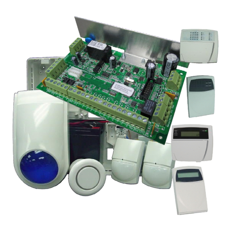
AAP ESL KIT Instruction sheet

QUICKFIT
INSTALL HOOK-UPSHEET
FOR
ESLKIT
REV1.17 OP

PROGRAMMING STARTS
Page2
ChangingEntrydelay’s
Zone 1issetat 20 secondsbydefault.
Thisishowlong the panelgivesyoutogetinand disarmitafter asensor hasbeentripped.
Each sensor hasitsowndelayfrom0to9999 seconds. Ifyouhave topass asensor togettothe keypad thenit
should have adelay.InInstaller Mode press <PROGRAM> <144> <ENTER> (thenselectthe zone youwish
tochange 1-8) and <ENTER> (thenputinthe new time 0-9999)and <ENTER>.
P144E1E[][ ][ ][ ]E(zone 1defaultdelayis20 seconds).
P144E2E[][ ][ ][ ]E(zone 2defaultdelayis0seconds).
ChangingExitdelay
Thisishowlong youhave togetoutofthe house before the panelgoesintoalarmmode.
Youcanhave from0to255second selected below.InInstaller Mode press <PROGRAM> <60> ENTER<1>
<ENTER> (thenputinthe new time 0-255) and <ENTER>.
P60 E1E[][ ][ ]E(the defaulttime is30 seconds).
OutputResetTimes
Thisishowlong the sirenswill sound before turnoff automatically.Time isinseconds.
InInstaller Mode press <PROGRAM> <40> <ENTER> (thenthe outputyouwishtochange 1or 2)and
<ENTER> (now putinthe new resettime 0-9999) and <ENTER>.
P40 E1E[][ ][ ][ ]E(output1defaultresettime is300 seconds).
P40 E2E[][ ][ ][ ]E (output2defaultresettime is300 seconds).
ChangingInstaller code
There isonlyone installer code,thisisfor youtoremember.Asdefaultitis000000.
Youmustbe inInstaller mode tochange the code,press <PROGRAM> <25> <ENTER> <1> <ENTER>
(thenputinyour new code) and <ENTER>.
P25 E1E[ ][ ][ ][ ][ ][ ] E
Changing/Addinguser codes
The panelhasthe abilitytohave up to100 user codes. Theycanhave a 1to6digit code.User Codesare stored
inat Address 1,slots1to100.Tochange codesyoumustbe inInstaller or Clientmode,thenpress
<PROGRAM> <1> <ENTER> thenthe slotyouwishtochange i.e. <1> and then<ENTER>, the keypad will
flashbackthe existing code (defaultcode is123).Now keyinyour new codei.e.(456)and press <ENTER>
the new code will be thenflashback.
P1E1E[ ][ ][ ][ ][ ][ ] E(Thisisthemastercodedefaultcode=123)P1E2E[ ][ ][ ][ ][ ][ ] E
P1E3E[ ][ ][ ][ ][ ][ ] EP1E4E[ ][ ][ ][ ][ ][ ] E
P1E5E[ ][ ][ ][ ][ ][ ] EP1E6E[ ][ ][ ][ ][ ][ ] E
P1E7E[ ][ ][ ][ ][ ][ ] EP1E8E[ ][ ][ ][ ][ ][ ] E
P1E9E[ ][ ][ ][ ][ ][ ] EP1E10E [ ][ ][ ][ ][ ][ ] E
EnteringInstaller mode
Ifyouwanttogetintoprogrammode press <PROGRAM> followed byyourinstaller code,defaultsetto 000000
and <ENTER> toconfirm.
ExitingInstaller Mode
Press the <PROGRAM> button,then <ENTER> .

Whenyouhave finished the programming options,aquicktestisrequired toconfirmallhardware and
software isworking correctly.
Run throughthe stepsbelow and tickthe box ifitoperatessuccessfully.
Make sure noone ismoving around the house,asthiscould affectthe test.
1.The keypad should nothave anyzone lightson.Thereadylightshould be onsteady.
Areall thelightsright?yesif no therecould bea wiringproblemcheckyourwork.
2.Getsomeone else towalkinfrontofthe sensors,the corresponding zone 1or 2should comeon.
Dotheycome on attherighttime?yesif no therecould bea wiringproblemcheckyourwork.
3.Nowtestall the user codes. Startbytyping inuser code 1followed byenter,the keypadshould start
beeping asitarms, thentypeitinagain,the keypadshould goquietasitdisarms.
Repeat thistestfor alluser codes.
Doall ofthecodesarmanddisarmthepanel?yesif no gobackandchecktheusercode slots,to
see weatherthe rightcodeshasbeenentered.
4.Nexttopressthe ARMbutton,tosee ifthere isenoughtime togetoutofthe house,before the exitdelay
beepsstop.
Canyou getoutbeforethebeepsstop?yesif no youwill needto extend theexitdelay.
5.Nowwiththe panelARMEDsee ifyoucangetbackinside tothe keypad and disarmthe alarmbefore the
sirensgooff.
Canyou disarmbeforethesirensgooff?yesif no youwill needto increasetheentrydelaytimes.
6.The finaltestistomakesure the sirensandstrobe gooff after the entrydelayhasfinished.Soarmthe
alarm,waitfor the beepstostop thenmove infrontofasensor,the keypad should startbeeping againand as
soonasthe entrydelayisup the sirensand strobe will gooff,once checked enter auser code todisarmand
turnofthe sounders.
Doestheexternalsirenwork?yes
Doestheexternalstrobework?yes
Doestheinternalsirenwork? yesif no to anyofthesecheckwiringandpolarityofdevices.
The alarmpanelisnow readyfor generaluse
Areyou happywiththeinstallation?
yes
Signhere.Date.//
Page3
TESTING

Page4
DIALLERSETUP- FORMONITORING STATION
Your Elite S-Lite Controller isequipped withanonboard dialler,capableofcommunicating incontactid.
Ifyouare required toconnecttoacentralmonitoringstationyouwillneed tocomplete the following steps.
Contactamonitoring stationofyour choice,theywillissue youanaccountnumber and telephone number.
Name ofmonitoring station___________________________ Contactphone number_____________
Your Accountnumber [ ][ ][ ][ ]
Telephone number 1[ ][ ][ ][ ][ ][ ][ ][ ][ ][ ][ ]
Telephone number 2[ ][ ][ ][ ][ ][ ][ ][ ][ ][ ][ ] (thisisoptional)
Step 1:Connectacross the incoming phone line betweenthe streetand the firstjackpoint.
Step 2:Enable the dialler.InInstaller Mode press <PROGRAM> <175> <ENTER> <1> <ENTER>
(thenturnONoption1) and <ENTER>.
P175E1E1E
Step 3:Accountnumber.InInstaller Mode press <PROGRAM> <62> <ENTER> <1> <ENTER>
(thenputinthe 4digitaccountnumber) <ENTER>.
i.e.P62E1E1234E (the new accountcode would be 1234)
Step 4:Phone number 1,InInstaller Mode press <PROGRAM> <181> <ENTER> <1> <ENTER>
(now keyinyour givenphone number 1) and <ENTER>.
I.e.P181 E1E095551234E (the new phone number 1would be 095551234)
Phone number 2,InInstaller Mode press <PROGRAM> <181> <ENTER> <2> <ENTER>
(now keyinyour givenphone number 2) and <ENTER>.
I.e.P181 E2E095554321E (the new phone number 2would be 095554321)
Step 5:Prepare for dialler test.Firstwe willtemporarilydisablesounders. InInstaller Mode press
<PROGRAM> <25> <ENTER> <9> <ENTER> <1> <2> <ENTER> (outputs1&2have
beendisabled untilanArmcycle hastakenplace).
P25 E9E12E
Step 6:Exitprogrammode bypressing and holding <PROGRAM>
Step 7:Testing.Pressthe <ARM> buttonthe exitdelaywill start.Whenitstopswalkinfrontofeach
detector,thengobacktothe keypad tosee ifLED’s1&2are now flashing and the keypad is
squealing.Assoonasthe entrydelayhasfinished,the panelshouldstartdialling out.Youwont
be able tohearitdialout,butifyoupickup aphone inthe house itshould nothave adialtone.
Leave the panelfor about2minutesthenkeyinausercode i.e.<123> followed by <ENTER>.
The panelshould now be disarmed.
Step 8:Confirming.Now contactthe monitoring stationand askthemiftheyreceived 3differentmonitoring
messagesfromyour accountcode.Theyshould be:
Alarmactivation on zone1.
Alarmactivation on zone2.
Alarmrestored.
Dialler Setupis Complete

DIALLERSETUP- FORPERSONALMONITORING
Ifyoudon’twantyour alarmtobe monitored byasecuritycompany,butstill wishtoknow ifanyactivationsoc-
curs, thenthe DomesticDialoptioncould be for you.
Ifaphone number onyour Elite S-Lite Controller’sissettoDomesticDial,whenanactivationoccursthat number
willbe calledand sirentone willbe played downthe line toyou.Thenyouneed toacknowledgeitbypressingthe
#keyonthe phone.
Telephone number 1[ ][ ][ ][ ][ ][ ][ ][ ][ ][ ][ ]
Telephone number 2[ ][ ][ ][ ][ ][ ][ ][ ][ ][ ][ ]
Telephone number 3[ ][ ][ ][ ][ ][ ][ ][ ][ ][ ][ ]
Telephone number 4[ ][ ][ ][ ][ ][ ][ ][ ][ ][ ][ ]
Withthe Elite S-Lite youcanreportbothFormats‘ContactIDand DomesticDial’onthe same job.
Aseach phone number issetup independently.
Step 1:Connectacross the incoming phone line betweenthe streetand the firstjackpoint.
Step 2:Enable the dialler.InInstaller Mode press <PROGRAM> <175> <ENTER> <1> <ENTER>
(thenturnONoption 1) and <ENTER>.
i.e. P175 E1E1E
Step 3:Phone number 1to8,InInstaller Mode press <PROGRAM> <181> <ENTER> <1-8>
<ENTER> (now keyinyour phone number) and <ENTER>.
i.e.P181 E1E021555123E (the new phone number 1would be 021555123)
Step 4:Phone number 1to8Reporting Format.InInstaller Mode press <PROGRAM> <182> <ENTER>
<1-8> <ENTER> (now turnONoption 2) and <ENTER>.
i.e. P182 E1E2E (phone number 1isnow settoDomesticDial).
Step 5:MaximumDialAttempts.Each phone number settoDomesticDialwill need dialattemptschanged.
InInstaller Mode press <PROGRAM> <184> <ENTER> <1-8> <ENTER> <3> <ENTER>.
i.e. P184 E1E3E (phone number 1now hasmaximumdialattemptssetto3).
Step 6:Reporting Options.Each phone number settoDomesticDialwill need 2reporting optionsturned
off.SoinInstaller Mode press
<PROGRAM> <176> <ENTER> <4> <ENTER><0> and <ENTER>.
Then <PROGRAM> <176> <ENTER> <5> <ENTER> <0> and <ENTER>.
i.e. P176 E4E0E (mainsfail,reporting ondomesticdialhasbeenturned off).
i.e. P176 E5E0E (mainsrestore,reporting ondomesticdialhasbeenturned off).
Step 7:Exitprogrammode bypressing and holding <PROGRAM>
Step8:Testing.Withthe phone learntintoslot1onhand,Armthe paneland waitfor the exitdelayto
finish.ThenwalkinfrontofaPIR,the entrydelayshould start,followed bythesirenssounding.
Disarmthe paneltomake the sirensstop.The phone should now be ringing,answer itandlisten.
A sirentone should playfor 3secondson2secondsoff.While the tone isoff press and hold the #
keytoacknowledge the call,the alarmpanelwillthenhang up.(ifthe #keywillnothang up the
paneltryadifferentkey)
Page5

E16LEDKP
Cable EntryPoint
PCBfitshere
17 voltAC
power leads
HARDWARE CONFIGURATION
Page6
Screw PCB
downin
these points.
BATTERY
GOESHERE WIRE230V
MAINSIN
HERE.
INSIDEVEIWOFPLASTICCABINET
POPOUT CABLECLAMPFORMAINSLEAD.
Endviewof
Keypad
Carefullyslideaflatbladescrewdriver
intoslotstoremoveback.
Removingbackfrom keypad.
CUT THISSUPPORTOFF

5YearWarranty
Thankyouforpurchasing another qualityArrowheadProduct.
WeguaranteetoreplaceorrepairArrowheadManufacturedproductfoundto
be faultydue todefectivematerialsorworkmanshipfor
aperiodof 5yearsfromdateof purchase.
Thecustomershall assoonaspracticableafterthediscoveryof anysuchdefect orfault,
returnthegoodsordefectivepartsthereof, toArrowheadAlarmProducts.
Freighttoandfromourstoresisyourcare.
Thecompanyshallnotbeliableforanydirect orconsequentiallossordamageattributedtothefault.
Norshall thecompanybeliableforanypersonalinjuryofanykind attributabletothefault.
Thecustomerwillkeepthecompanyindemnifiedagainstanysuchclaim.
AnyattemptbythecustomertorepairthegoodswithoutwrittenpermissionbythecompanycouldvoidtheWarranty.
Page7

E16LEDKP
RESISTORCOLOURCODES:
2K2= = RED,RED,RED,GOLD.
4K7= = YELLOW,VIOLET,RED,GOLD.
8K2= = GREY,RED,RED,GOLD.
SIREN
TAMPER
LED
STROBE
EOL
SS-1C
SATELLITESIREN
ESLCONNECTIONDIAGRAM
230V
AC
Input
Lin
Dat
Clk
Neg
Pos
Gnd 12V1C23C4Tmp Gnd
Outputs
Gnd 12V1234
ELITES-LITE
V908.12
In
Lin
Out AC
AC
Red
Blk
17VAC
Zone 1Passive
Infra-RedDetector
0v
12v
EOLTAMPEREOLRELAY
2k2
Zone 2Passive
Infra-RedDetector
0v
12v
EOLTAMPEREOLRELAY
2k2
HOUSE
PHONES
PHONELINE
OFF THE
STREET
SILICONEFILLEDCRIMPS
TELEPHONEWIRING OPTION1:Standard analogue line
PIEZO
SIREN
2k2
2k2
P
N
Keypad
TerminalBlock
ON
12
0V
C
D
1
ANT
RX-16 MF349 v090618
(303, 433 &915MHz)
OptionalRadioReceiverConnectshere: PIR2
PIR1
INTERNAL
EXTERNAL
KEYPAD1
RECEIVER
PHONELINE
OFF THE
STREET
WITHADSLENABLED ADSLMODEM
LINE
PHONE
DSL008
ADSLLINEFILTER
SILICONEFILLEDCRIMPS
TELEPHONEWIRING OPTION2:withhighspeed internet(broadband)
ADSL FILTERNOTSUPPLIEDINKIT
TELEPHONEWIRING OPTION3:withVoice over IP System
IP-MODULENOTSUPPLIEDINKIT
InternetRouter
VoIP phone lineswillNotwork
withthe AlarmSystem.
InternetConnection
IP-MODULE
Lin
Dat
Clk
Neg
Pos
12 Volt
SLA
Battery
Table of contents
Other AAP Security System manuals