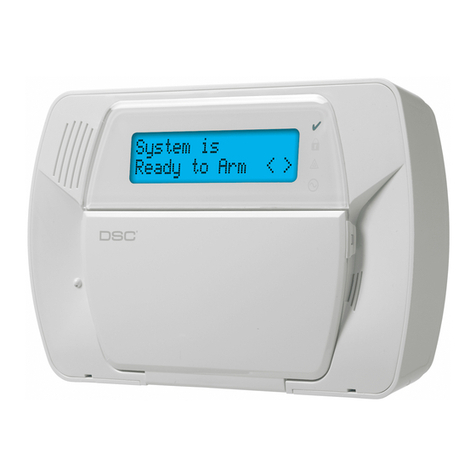
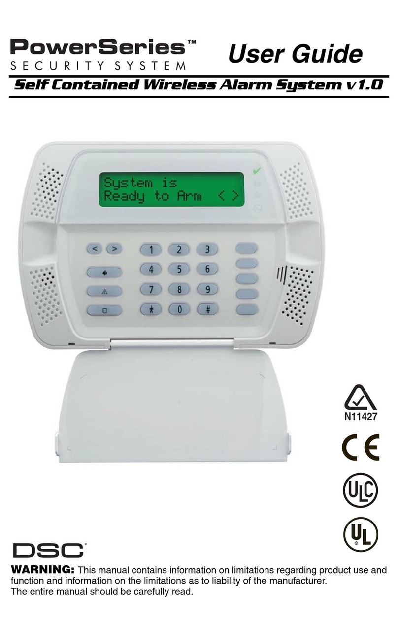
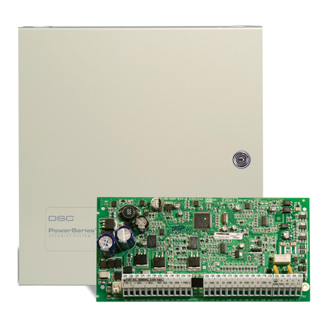
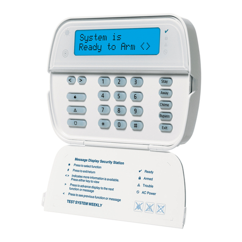
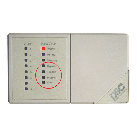
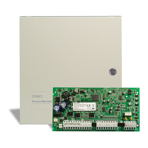
DSC PC1510 User manual

Installation
Manual
PC151O
• W A R N I N G •
This manual contains information on limitations regarding product use and
function and information on the limitations as to liability of the manufacturer.
The entire manual should be carefully read.
Software Version 4.1
DLS-1 V6.5 and up

34
This manual is for the PC1510 software version 4.1
INDUSTRY CANADA NOTICE
NOTICE: The Industry Canada label identifies certified equipment. This certification
means that the equipment meets certain telecommunications network protective,
operationalandsafetyrequirements.IndustryCanadadoesnotguaranteetheequipment
will operate to the user’s satisfaction.
Before installing this equipment, users should ensure that it is permissible to be
connected to the facilities of the local telecommunications company. The equipment
must also be installed using an acceptable method of connection. The customer should
be aware that compliance with the above conditions may not prevent degradation of
service in some situations.
Repairs to certified equipment should be made by an authorized Canadian maintenance
facility designated by the supplier. Any repairs or alterations made by the user to this
equipment, or equipment malfunctions, may give the telecommunications company
cause to request the user to disconnect the equipment.
Usershouldensurefor their own protectionthattheelectrical ground connections ofthe
power utility, telephone lines and internal metallic water pipe system, if present, are
connected together. This precaution may be particularly important in rural areas.
CAUTION:Usersshouldnotattempttomake such connections themselves,butshould
contact the appropriate electric inspection authority, or electrician, as appropriate.
The Load Number (LN) assigned to each terminal device denotes the percentage of the
total load to be connected to a telephone loop which is used by the device, to prevent
overloading. The termination on a loop may consist of any combination of devices
subjectonlytotherequirementthatthe total of the Load Numbers of all the devices does
not exceed 100.
The Load Number of this unit is 2.
AVIS: L’étiquette de l’Industrie Canada identifie le matériel homologué. Cette
étiquette certifie que le matériel est conforme à certaines normes de protection,
d’exploitation et de sécurité des réseaux de télécommunications. Industrie Canada
n’assure toutefois pas que le matériel fonctionnera à la satisfaction de l’utilisateur.
Avant d’installer ce matériel, l’utilisateur doit s’assurer qu’il est permis de le raccorder
auxinstallationsdel’entrepriselocaledetélécommunication.Lematérieldoitégalement
être installé en suivant une méthode acceptée de raccordement. L’abonné ne doit pas
oublier qu’il est possible que la conformité aux conditions énoncées ci-dessus
n’empêchent pas la dégradation du service dans certaines situations.
Lesréparations de matériel homologué doivent être effectuées par uncentre d’entretien
canadienautorisédésignéparlefournisseur.Lacompagniedetélécommunicationspeut
demander à l’utilisateur de débrancher un appareil à la suite de réparations ou de
modifications effectuées par l’utilisateur ou à cause de mauvais fonctionnement.
Pour sa propre protection, l’utilisateur doit s’assurer que tous les fils de mise à la terre
de la source d’énergie électrique, les lignes téléphoniques et les canalisations d’eau
métalliques, s’il y en a, sont raccordés ensemble. Cette précaution est particulièrement
importante dans les régions rurales.
AVERTISSEMENT: L’utilisateur ne doit pas tenter de faire ces raccordements lui-
même; il doit avoir recours à un service d’inspection des installations électriques, ou à
un électricien, selon le cas.
L’indice de charge (IC) assigné a chaque dispositif terminal indique, pour éviter toute
surcharge, le pourcentage de la charge totale qui peut être raccordée à un circuit
téléphonique bouclé utilisé par ce dispositif. La terminaison du circuit bouclé peut être
constituée de n’importe quelle combinaison de dispositifs, pourvu que la somme des
indices de charge de l’ensemble des dispositifs ne dépasse pas 100.
L’Indice de charge de ce produit est 2.

i
TABLE OF CONTENTS
FEATURES 1
SPECIFICATIONS 1
INSTALLATION 2
Mounting the Panel ........................................................................................................................................................... 2
Mounting the Keypad ....................................................................................................................................................... 2
Auxiliary Power Connection .............................................................................................................................................. 2
PGM Terminal Connections.............................................................................................................................................. 2
Bell/Siren Connection........................................................................................................................................................ 2
Keypad Wiring .................................................................................................................................................................. 2
Fire Zone Wiring................................................................................................................................................................ 3
Burglary Zone Wiring ........................................................................................................................................................ 3
AC Power Wiring ............................................................................................................................................................... 4
Battery Connection ........................................................................................................................................................... 4
Telephone Line Wiring ...................................................................................................................................................... 4
GUIDELINES FOR LOCATING SMOKE DETECTORS 5
KEYPAD FUNCTIONS 6
Introduction ....................................................................................................................................................................... 6
Master Code ..................................................................................................................................................................... 6
2nd Master Code .............................................................................................................................................................. 6
Installer’s Programming Code .......................................................................................................................................... 6
Arming............................................................................................................................................................................... 6
Auto-Bypass/Home-Away Arming .................................................................................................................................... 6
Arming Without Entry Delay.............................................................................................................................................. 6
Disarming .......................................................................................................................................................................... 6
Zone Bypassing ................................................................................................................................................................ 6
Trouble Conditions............................................................................................................................................................ 7
Alarm Memory................................................................................................................................................................... 7
Downloading Callup Command........................................................................................................................................ 7
User Programming Commands........................................................................................................................................ 7
EEPROM Reset ................................................................................................................................................................. 8
User Function Commands ................................................................................................................................................ 8
Setting the Clock ....................................................[∗]+[6]+[Master Code]+[1]........................................................ 8
Set Auto-Arm Time .................................................[∗]+[6]+[Master Code]+[2]........................................................ 8
Quick-Arm ON/OFF ................................................[∗]+[6]+[Master Code]+[4]........................................................ 8
Auto-Arm ON/OFF ..................................................[∗]+[6]+[Master Code]+[5]........................................................ 8
Door Chime ON/OFF .............................................. [∗]+[6]+[Master Code]+[6]........................................................ 8
Bell Test ..................................................................[∗]+[6]+[Master Code]+[8]........................................................ 9
Installer’s Test ON/OFF .......................................... [∗]+[6]+[Master Code]+[0]........................................................ 9
Utility Output Command.........................................[∗]+[7] or [∗]+[7]+[Access Code............................................. 9
Installer’s Programming Command .......................[∗]+[8]+[Installer’s Code] .......................................................... 9
Arming without Entry Delay .................................... [∗]+[9]+[Access Code]+[1] ....................................................... 9
Arming For The Night .............................................[∗]+[1]......................................................................................... 9
Quick-Exit Command ............................................. [∗]+[0] when Armed ................................................................... 9
Quick-Arm Command ............................................[∗]+[0]......................................................................................... 9
Utility Output Command ................................................................................................................................................... 9
Installer’s Programming Command .................................................................................................................................. 9
Arming without Entry Delay .............................................................................................................................................. 9
Arming For The Night........................................................................................................................................................ 9
Quick-Exit Command........................................................................................................................................................ 9
Quick-Arm Command ....................................................................................................................................................... 9
Keypad Zones................................................................................................................................................................... 9

ii
PROGRAMMING GUIDE 10
Introduction ..................................................................................................................................................................... 10
Programming .................................................................................................................................................................. 10
Program Data Review ..................................................................................................................................................... 10
Binary Data Display ........................................................................................................................................................ 10
HEX Data Programming.................................................................................................................................................. 10
PROGRAMMING SECTIONS 11
[00] Binary Programming ............................................................................................................................................... 11
[01] 1st Phone Number .................................................................................................................................................. 11
[02] 1st Account Code ................................................................................................................................................... 11
[03] 2nd Phone Number ................................................................................................................................................. 11
[04] 2nd Account Code .................................................................................................................................................. 11
[05] to [10] Reporting Codes ......................................................................................................................................... 11
[05] Zone Alarm Reporting Codes ................................................................................................................................. 11
[06] Zone Restoral Reporting Codes ............................................................................................................................. 11
[07] Closing (Arming) Reporting Codes......................................................................................................................... 12
Partial Closing Reporting Code ...................................................................................................................................... 12
[08] Opening (Disarming) Reporting / Codes After Alarm Reporting Code.................................................................. 12
[09] Priority Alarms and Restorals.................................................................................................................................. 12
[10] Maintenance Alarms and Restorals........................................................................................................................ 12
[11] Zone Definitions....................................................................................................................................................... 12
[12] 1st System Option Code ......................................................................................................................................... 13
[13] 2nd System Option Code........................................................................................................................................ 14
[14] 3rd System Option Code ........................................................................................................................................ 14
[15] Communication Variables ....................................................................................................................................... 14
[16] Zone Bypass Mask.................................................................................................................................................. 14
[17] System Times .......................................................................................................................................................... 14
[18] Auxiliary Delay Loop / Entry/Exit Times .................................................................................................................. 15
[19] System Clock Times................................................................................................................................................ 15
[20] New Installer’s Code ............................................................................................................................................... 15
[21] New Master Code ................................................................................................................................................... 15
[22] 2nd Master Code .................................................................................................................................................... 15
[23] Communication Formats ......................................................................................................................................... 15
[24] Programmable Output Options / (PGM Terminal).................................................................................................. 16
[25] Communicator Call Directions ................................................................................................................................ 17
[26] Downloading Telephone Number ........................................................................................................................... 17
[27] Downloading Access Code..................................................................................................................................... 17
[28] Panel Identification Code ........................................................................................................................................ 17
[29] Number of Rings Before Answering ....................................................................................................................... 17
[30] Reset to Factory Default ......................................................................................................................................... 17
[31] 4th System Option Code......................................................................................................................................... 17
[32] 5th System Option Code......................................................................................................................................... 18
[33] Answering Machine Double Call Timer................................................................................................................... 18
[34] 6th System Option Code......................................................................................................................................... 18
[35] For Future Use......................................................................................................................................................... 18
[36] Keypad Lockout Control ......................................................................................................................................... 18
[90] Installer’s Lockout Enable ....................................................................................................................................... 18
[91] Installer’s Lockout Disable ...................................................................................................................................... 18
FOR THE RECORD 19
PROGRAMMING WORK SHEETS 28
HOOK-UP DIAGRAM 29

1
FEATURES SPECIFICATIONS
Keypad Programmable
The PC1510 is complete with a default program so that it is
operational with a minimum of programming. The control
panel is completely programmable from the keypad.
EEPROM Memory
ThepanelusesEEPROMmemorywhichwillretainallprogram
informationevenifACandbatterypowerareremovedfromthe
panel. The EEPROM memory can be reprogrammed
thousands of times.
Static/Lightning Protection
The PC1510 has been carefully designed and tested to
providereliableprotectionagainststaticandlightning-induced
transients. Our special “Zap-Trac” circuit board design
catches high voltage transients right at the wiring terminals,
and transient protection devices are placed in all critical
areas to further reduce damaging voltages.
Supervision
• Low or disconnected battery
• Loss of AC power
• Fuse open
• Loss of time on system clock
• Microprocessor “Watchdog” circuit
Operation
• Download / Upload capability
• Programmable auto downloading
• 60 second bypass of zones on power up
• Swinger shutdown
• Transmission delay
• Six access codes
• “Master key” code
• All zones programmable as fire zones
• Temporal fire bell pattern
• Programmable test transmission
• Zone bypass from the keypad
• Six zones
• Bell / Siren zone
• Programmable output
• Four programmable options
• Three dedicated keys (Fire/Emergency/Panic)
• Backlit aesthetically pleasing keypad
PC1510 Control Panel
• Sixfullyprogrammablezones
- EOL resistor (±30% EOL) supervised option
-all zones programmableas fire zones.
-maximumzoneloopresistance 100ohms
• Bell / Siren outputs: 1 A
- steady for burglary
- pulsed for fire
• Programmableoutput:300mA
-9programmableoptions
• Auxiliarypoweroutput:475 mA
• PC1500RKkeypad:5maximum
- Subtract35mAfromtheAuxiliarySupplyratingforeach
keypad in excess of 3 connected to the PC1510
• Battery:12VDC,4Ahminimum
• Battery Cutoff between 9 V to 10 V to prevent battery
damage due to deep discharging
• Transformer: 16 VAC, 40 VA
• Panel dimensions
- 10” high x 8” wide x 3” deep (254 x 208 x 76 mm)
- Surface mount
• Panel colour: light beige
PC1500RK Keypad
• Three keypad activated zones: Fire, Emergency, Panic
• Backlit keys
• 5 system lights:
Ready, Armed, Memory, Bypass, Trouble
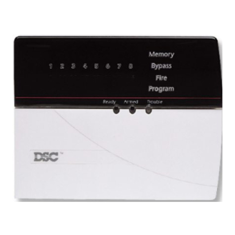
• 6 zone lights
• Keypad dimensions
- 4.5" H × 4.5" W × 0.93" D (114 × 114 × 23.6 mm)
- Surface mount
• Keypad colour: white

2
INSTALLATION
AUX
12VDC
FUSE
1A
LOAD
LOAD
PGM
DEVICE
CONTROLLED
DEVICE
300 mA MAX
TO AUX+
TERMINAL
Bell Loop Wiring Chart
AWG AWG AWG AWG AWG
Current 14 16 18 19 22
mA Distance to last bell or siren (ft./m.)
100 2375/724 1500/457 940/287 750/229 370/113
200 1190/363 750/229 470/143 370/113 185/ 56
300 790/241 500/152 310/ 94 250/ 76 120/ 37
400 595/181 375/114 235/ 72 185/ 56 90/ 27
500 475/145 300/ 91 190/ 58 150/ 46 75/ 23
600 400/122 250/ 76 155/ 47 125/ 38 60/ 18
700 340/104 210/ 64 135/ 41 105/ 32 50/ 15
800 300/ 91 190/ 58 115/ 35 90/ 27 45/ 14
900 265/ 81 170/ 52 100/ 30 80/ 24 40/ 12
1000 240/ 73 150/ 46 90/ 27 75/ 23 35/ 11
BELL
12VDC
FUSE
5A
BELL OR
SIREN
12VDC
1A MAX
AUX KEYPAD
YEL GRN
1500RK OR
1500RKF
KEYPAD
1500RK OR
1500RKF
KEYPAD
GRN
YEL
RED
BLK
GRN
YEL
RED
BLK
Mounting the Panel
Select a dry location close to an unswitched AC source and
close to the telephone line connection. Remove the printed
circuit board, the mounting hardware and the keypad from
the cardboard retainer inside the cabinet. Before attaching
the cabinet to the wall, press the four white nylon printed
circuit board mounting studs into the cabinet from the back.
Once the cabinet is mounted to the wall, pull all the cables
into the cabinet and prepare them for connection. Use a
meter to test the wiring for opens, shorts and grounds. Press
thecircuitboardontothewhitenylonmountingstuds.Complete
all wiring to the control panel before applying AC power or
connecting the battery.
Mounting the Keypad
Keypads should be located close to the designated “Entry-
Exit” door(s) and mounted at a height convenient for all
users.
NOTE: Complete all wiring to the control panel before
applying AC power or connecting the battery.
Auxiliary Power
Connection
Theauxiliarypowersupplycanbe
used to power keypads, motion
detectors and other devices that
require12VDC.SeetheFireZone
Wiring section for the connection
of 4-wire smoke detectors. The
total load for the auxiliary power
output must be calculated for all
devices connected across the
AUX +/- terminals and for devices connected between the
AUX + and PGM terminals. The output current cannot
exceed 475 mA.
PGM Terminal Connections
The PGM terminal is a switched
negative output which can be
controlled by various
programming options (See
Programming Guide Section
[24]). Devices controlled by the
PGM output must be connected
betweenthePGMterminal,which
is (-) and the Aux. (+) terminal.
Bell/SirenConnection
Wirerundistancesareinfeet/metersfromthecontrolpanelto
thelastdeviceontheloop.Calculationsarebasedon12VDC
at the panel with a maximum 10% voltage drop at the last
device.Observepolaritywhenconnectingsirendrivers,sirens
andpolarizedbells.
Keypad Wiring
Up to three keypads may be connected in parallel. Do not
connect multiple keypads on the same keypad wire run. For
Standby Loading purposes, use a current draw of 35 mA per
keypad. This represents the panel in the disarmed state with
two zones open.

3
Wiring Chart PC1500RK
Wire Gauge Max. Run Length
(AWG) Keypad to Panel
24 260’ (79m)
22 420’ (127m)
20 660’ (200m)
19 830’ (252m)
18 1050’ (318m)
AUX + PGM Z1 COM
DETECTOR
POWER
12VDC
IN
OUT
N.O.
ALM
-
OUT
+
-
IN
+
BLK WHT
RED GRN
LATCHING 4-WIRE
SMOKE DETECTOR
5600Ω0.5W
END OF LINE
RESISTOR
RM-1 POWER LOOP
SUPERVISORY RELAY
12VDC 35mA MAX.
WHT
ALARM INITIATING
LOOP; RESISTANCE 100Ω
AWG AWG AWG AWG AWG AWG
14 16 18 19 22 24
19 800' 12 450' 7800' 6200' 3000' 1900'
6035m 3794m 2377m 1889m 914m 579m
Figuresbasedon maximumloop resistanceof100 ohms.
Alarm Initiating Loop Wiring Chart
Wire
Gauge
Distance
to EOL
Resistor
Max. Wire Run to E.O.L. Relay
AWG AWG AWG AWG AWG
14 16 18 19 22
4750' 3000' 1880' 1500' 750'
1447m 914m 573m 457m 228m
2375' 1500' 940' 750' 370'
723m 457m 286m 228m 112m
1190' 750' 470' 370' 180'
362m 228m 143m 112m 56m
790' 500' 310' 250' 120'
240m 152m 94m 76m 36m
595' 375' 235' 185' 90'
181m 114m 71m 56m 27m
Current
mA
50
100
200
300
400
Wirerundistancesareinfeet/metersfromtheAux.+/-terminalstothe
End-Of-LinePowerSupervisoryRelay.Figuresarebasedon12VDCat
the Aux +/- terminals with a maximum 10% voltage drop at the RM-1
relay.
Fire Zone Power Wiring Chart
Z1 COM Z2
NC
NO NC
NC
5600Ω0.5W
END OF LINE
RESISTOR
5600Ω0.5W
END OF LINE
RESISTOR
EOL RESISTOR
LOOPS USING
NO & NC
DEVICES
EOL RESISTOR
LOOPS USING
NC DEVICES
ONLY
Zone Wiring Chart
Figures based on maximum loop
resistanceof 100ohms.
Wire Gauge Max.Run Lengthto
(AWG) End-of-Lineresistor
24 1900’ (579m)
22 3000’ (914m)
20 4900’ (1493m)
19 6200’ (1889m)
18 7800’ (2377m)
Thewiringtablegivesthewirerunlengthfromthecontrolpanel
tothekeypadforvarious gauges ofwire.Wirerunlengthsare
basedonthemaximumcurrentdrawnbythekeypad.(Alllights
ON).
Iftwowiresofthesamegaugeareparalleled,therunlengthcan
bedoubled.eg.If8#22AWGwiresareused,2red,2blk,2grn
and2yel,therunlengthwouldgofrom420’to840’(127to254
m).
Burglary Zone Wiring
Burglary zone definition, (eg. Delay, Instant, 24 Hr. etc.) is
programmed via the keypad. See the Programming Guide,
Section [11].
Fire Zone Wiring
Anyoneofthe6zonesmaybeprogrammedasaFireLoop. See
ProgrammingGuideSection[11].
Smoke detectors should be the latching type and have N.O.
alarm initiating contacts. Power wiring from the AUX + /
PGM terminals should be supervised using an RM-1 relay
after the last smoke detector. The RM-1 N.O. contacts
(closed with power applied) should be wired in series with
the alarm initiating end-of-line resistor so that should power
to the detector(s) fail, a fire loop trouble will be initiated.

4
AC
16VAC
40 VA MIN
CSA LISTED
TRANSFORMER
50 OR 60 Hz
R-1 T-1 RNG TIP
GRN
RED
BRN
GRY
RJ31-X
TELEPHONE
PLUG
AC Power Wiring
CompleteallwiringtothecontrolpanelbeforeconnectingAC
power or the battery. Do not plug the transformer into an
outlet that is controlled by a switch.
Telephone Line Wiring
Donotconnectthealarmpanelcommunicatortotelephone
linesintendedforusewithfacsimile(fax)machines. These
linesmayincorporateavoicefilterwhichdisconnectsthe
lineifotherthan fax signals aredetected. Thismayresult
in incomplete transmissions from the alarm panel
communicator.
RED
BATTERY CHARGE CURRENT
IS 360 mA MAX
12 VOLT 4 Ah.
GEL - CELL
+
BATTERY CAPACITY FOR
EMERGENCY STANDBY
IS AT LEAST 4 HOURS IF
THE TOTAL LOAD (BELL
AUXOUTPUTS)IS800mA
OR LESS
BLK
-
BatteryConnection
Ifthebattery is reverse connected, the5Afuse will blow. The
batterychargingvoltageisfactorysetandnormallyneedsno
adjustment.Ifthebatterychargingvoltageisoutofadjustment,
contact your service representative.
NOTE: The PC1510 will not power up, even with a fully
charged battery, until AC power is connected. After an
extended AC power failure, the battery will be automatically
disconnected when its voltage drops to between 9 V and 10
V. Thisfeatureisdesignedto preventdamagetothebattery
duetodeepdischarging.

5
GUIDELINES FOR LOCATING SMOKE DETECTORS
Experiencehasshownthatallhostilefiresinfamilylivingunits
generate smoke to a greater or lesser extent. Experiments
usingtypicalfiresinfamilylivingunitsindicatethatdetectable
quantitiesofsmokeprecededetectablelevelsofheatinmost
cases.Forthesereasons,smokedetectorsshouldbeinstalled
outside of each sleeping area and on each additional story
of the family unit.
Thefollowinginformationisforgeneralguidanceonlyanditis
recommendedthatthesmokedetectormanufacturer'sliterature
beusedfordetailedinstallationinstructions.
It is recommended that additional smoke detectors beyond
those required be installed for increased protection. The
added areas include: basement, bedrooms, dining rooms,
furnace room, utility room and hallways not protected by the
requireddetectors.
A smoke detector should be located between the sleepingA smoke detector should be located between the sleeping
A smoke detector should be located between the sleeping
area and the rest of the family unit.area and the rest of the family unit.
area and the rest of the family unit.
In the family living units with more than one sleeping area,In the family living units with more than one sleeping area,
In the family living units with more than one sleeping area,
a smoke detector should be located to protect eacha smoke detector should be located to protect each
a smoke detector should be located to protect each
sleeping area.sleeping area.
sleeping area.
A smoke detector should be located on each story of theA smoke detector should be located on each story of the
A smoke detector should be located on each story of the
living unit.living unit.
living unit.
Smoke Detector mounting - “Dead”Air Space. The smokeSmoke Detector mounting - “Dead”Air Space. The smoke
Smoke Detector mounting - “Dead”Air Space. The smoke
from a fire generally rises to the ceiling, spreads outfrom a fire generally rises to the ceiling, spreads out
from a fire generally rises to the ceiling, spreads out
across the ceiling surface and begins to bank down fromacross the ceiling surface and begins to bank down from
across the ceiling surface and begins to bank down from
the ceiling. The corner where the ceiling and wall meetthe ceiling. The corner where the ceiling and wall meet
the ceiling. The corner where the ceiling and wall meet
is an air space into which the smoke may have difficultyis an air space into which the smoke may have difficulty
is an air space into which the smoke may have difficulty
penetrating. In most fires, this “dead”air space measurespenetrating. In most fires, this “dead”air space measures
penetrating. In most fires, this “dead”air space measures
about 4 in. (0.1m) along the ceiling from the corner andabout 4 in. (0.1m) along the ceiling from the corner and
about 4 in. (0.1m) along the ceiling from the corner and
about 4 in. (0.1m) down the wall as shown in Figure 4.about 4 in. (0.1m) down the wall as shown in Figure 4.
about 4 in. (0.1m) down the wall as shown in Figure 4.
Detectors should not be placed in the dead”air space.Detectors should not be placed in the dead”air space.
Detectors should not be placed in the dead”air space.

6
Auto-Bypass/Home-Away Arming
If a correct access code is entered, and you do not
exit the
premises, the system will, at the end of the exit delay time,
arm with interior zones automatically bypassed if those
interior zones have been programmed as “Home-Away”
zones. The“Bypass”lightwillcomeON.(Seeprogramming
section [11], Zone Definitions for programming zones as
“Home-Away”).
This is a convenience feature for the user who wishes to
remain at home with the system armed. The user does not
have to manually bypass the interior zones.
Toreactivatetheinterior zones thathavebeenautomatically
bypassed, press [∗][1]. The “Bypass”light will go out. If the
bypassed zones were programmed as Home-Away with
delay, the “Bypass”light will go out after the delay. This
command is a quick method of fully arming the system
before going to bed and is useful for the user who has a
keypad outside the areas protected by the interior zones.
Arming Without Entry Delay
To eliminate the Entry Delay, arm the system using [∗][9],
[any valid access code]. An exit may be made as in normal
arming. The system will arm as described above in Auto-
Bypass/Home-Awayarmingwhetheranexitismadeornot.
The “Armed”light will flash to indicate that the system is
armed without the entry delay.
Disarming
Enter the premises through the designated entry-exit door.
The keypad sounder will be on as a reminder to disarm the
system. Go to the keypad and enter a valid access code. If
an error is made entering the code, press the [#] key and
enter the code again. The “Armed”light will go out and the
sounderwillstop.Thecorrectaccesscodemustbeentered
before the entry time expires or the panel will go into alarm.
To change the entry time see Installer’s Programming
section [17].
If an alarm occurred while the panel was armed, upon
disarming the “Memory”light and the zone light(s) of the
zone(s) that caused the alarm will flash for two minutes.
Pressing the [#] key will stop the flashing, extinguish the
zone light(s) and return the panel to the ready mode. The
“Memory”light will stay on steady to indicate that an alarm
did occur during the last armed period. To view the zone(s)
that caused the alarm, see Alarm Memory Display [∗][3].
Zone Bypassing
[∗∗
∗∗
∗]+[1]
A bypassed zone will not cause an alarm. Use zone
bypassingwhenaccessisneededtopartofaprotectedarea
or if damage to contacts or wiring cannot be repaired
immediately. The panel can be armed with one or more
zones bypassed even if the zone(s) are open. The “Ready”
light will be ON and the “Bypass”light will be ON if a zone is
bypassed. A fire zone cannot
be bypassed.
If the “Bypass”light is ON when arming, use the [∗][1]
command to display the bypassed zones and ensure that
any zone displayed as being bypassed is intentionally
bypassed.
Zone bypasses are automatically cancelled when the panel
is disarmed.
KEYPAD FUNCTIONS
Introduction
ThePC1500RKremotekeypadprovides complete information
andcontrolof thePC1510controlpanel. Thepanelcanbe fully
programmedfromthekeypad.The6zonelightsprovide alarm
and status indication for the alarm circuits. Each zone can be
programmed to be a burglary zone or a fire zone. The five
function lights guide the user in operating the system and the
built-insounderletstheuserhearcorrectkeyentriesandother
alert signals. The 12 digit keypad is used for code entry and
otherprogrammingfunctions.Thesinglebutton[F]ire,[A]uxiliary
and [P]anic keys provide the user with simple operation for
emergencysignalling.Allkeypadentriesaremadebypressing
one key at a time.
Master Code
AdefaultMasterCode “1234”is factoryprogrammedintothe
PC1510. The Master Code is used to arm and disarm the
panel, to reset the bells after an alarm, to program up to 5
additional codes using the [∗][5] command, and to enter
other user functions using the [∗][6] command. The panel
default program allows the user to change the Master Code.
The panel can be programmed, by the installer, so the user
cannot change the Master Code. See 2nd System Option
Code light 2.
2nd Master Code
AsecondMasterCodecanbeprogrammedintothePC1510.
This code can be changed by the installer only, and is useful
wheretherearemultiplepanelsinacomplex.The2ndMaster
Code may be used as a “Master Key”. The default 2nd
Master Code is blank.
Installer’s Programming Code
AdefaultInstaller’sProgrammingCode“1500”isprogrammed
intothePC1510.Usingthiscode and the [∗][8]command,the
installer can gain access to the system to enter panel program
information. This code can be changed by the installer.
Arming
Before arming the panel, close all protected doors and
windows and stop movement in areas covered by motion
detectors. If the “Trouble”light is on, check for the type of
trouble ([∗][2] command) and correct the fault condition. If
the “Bypass”light is on, insure that the zones bypassed are
bypassed intentionally, ([∗][1] command). If the “Ready”
light is not on, one or more zones are open. The system can
only be armed when the “Ready”light is ON. To arm, enter
a 4 digit access code. As each digit is entered, the keypad
sounder will beep. When the correct access code has been
entered the “Armed”light will come ON and the keypad will
beep 6 times. If the access code has been entered
incorrectly, the keypad will sound one long tone. Press the
[#] key and enter the access code again.
When the correct access code has been entered and the
“Armed”light is ON, exit through the designated entry/exit
door before the exit delay time expires. At the end of the
allowed exit time, all lights on the keypad will go out except
the “Armed”light. The “Bypass”light will be ON if a zone is
bypassed and if Show Bypassed Status While Armed is
programmed in section [31], zone light 4 ON.
See Installer’s programming section [∗][8] command for
instructions on changing the Exit Delay time.
7
To Bypass Zones:
Enter [∗][1] - the “Bypass”light will start flashing.
Enter[zonenumber tobebypassed];thezonelightwillcome
ON to indicate that the zone is bypassed. To remove a
bypass,enterthezonenumberandthezonelightwillgoOFF.
Continue entering the zone numbers for the zones you want
bypassed. Press [#] to return to Ready.
NOTE: Any zone defined as 24 Hour Bell, 24 Hour Bell/
Buzzer, or 24 Hour Buzzer cannot be bypassed while that
zoneis violated. Tobypass a 24 hourzone, the zone mustbe
physically restored.
To Recall Bypassed Zones:
Enter [∗][1][9]
This command will recall the last zone or group of zones that
were bypassed. If the same group of zones are bypassed
regularly, the bypass recall feature can be used instead of
bypassing the zones individually.
Bypass Disable:
The PC1510 can be programmed by the installer to prevent
certain zones from being bypassed by the user. Lights for
these zones will not come ON in response to the bypass
command. See the Zone Bypass Mask instruction in the
installer programming section [16].
Trouble Conditions
[∗∗
∗∗
∗]+[2]
The PC1510 continuously monitors a number of trouble
conditions. If one of these conditions occurs, the keypad
“Trouble”light will come ON and the buzzer will sound two
short beeps every 10 seconds. To silence the buzzer, press
the [#] key. The buzzer will stop but the “Trouble”light will
remain ON until the trouble condition is cleared. See the
Programming Guide section [10], Maintenance Alarms &
Restorals for a list of those zones that can be transmitted to
the monitoring station.
To view the trouble condition, press [∗][2].
1. Low Battery. If the battery voltage is low, the battery is
disconnectedorthe battery fuse is blown,atroublewillbe
displayed and can be reported.
2. AC Failure. On loss of AC power, the “Trouble”light will
come ON immediately, but the keypad buzzer will not
sound. ThekeypadbuzzerwillsoundifACpowerremains
off and the battery reaches a low voltage. The delay
before transmitting AC Fail can be programmed from 1 to
99 minutes. See Programming Section [17].
3. Fuse Failure - Bell / Siren or AUX Output. A trouble is
displayed if the Bell / Siren fuse is open. If the AUX output
fuse fails, it will not be displayed but will be transmitted if
programmed to do so.
4. Unsuccessful Communication Attempt If the digital
communicator is unsuccessful at communicating with the
monitoring station after 8 attempts at each phone number
that is tried, a trouble is generated. See section [15],
Communication Variables. If a later attempt at
communication is successful, the trouble is cleared. The
trouble can also be cleared by pressing the [#] key to exit
from the trouble view mode.
5. Fire Alarm Circuit Trouble An open circuit on the zone
programmedas a fireloop will initiatea trouble. See Zone
Definitions section [11] for fire loop zone assignment.
6. Loss of Time on System Clock When the PC1510 is
powered up or reset, the internal time of day clock needs
to be reset to the correct time. The trouble is cleared after
entering the trouble view mode then pressing [#] to exit.
The trouble will also be cleared on any attempt to set the
time of day. See [∗][6] User Function Command for
setting the clock. Press [#] to return to Ready. NOTE: A
trouble will not be generated if both the test transmission
and Auto-Arm times are not programmed with valid times.
NOTE:
If[9]is pressedwhileinthetroubledisplay mode,the
most recent trouble will be displayed on the zone lights. This
trouble memory is most useful as a diagnostic tool when
installing and servicing the PC1510. Press [#] to return to
“Ready”.
Alarm Memory
[∗∗
∗∗
∗]+[3]
Alarms caused during the previous armed period are stored
in memory. To view these alarms, press [∗] then [3]. The
“Memory”lightwillflashandthealarm(s)willbe displayed on
the flashing zone lights.
In addition to the last alarm memory, there are two history
levels. Afterenteringthememorymode,pressinganykey[0]
to [9] will display the two other levels of alarm history. Each
time a key is pressed, the keypad will beep 1, 2 or 3 times to
indicate which level of history is being viewed.
When the panel is armed, and if there is an alarm in the 1st
level, the 1st level is cleared and the contents moved to the
2nd level. The 2nd level contents are moved to the 3rd level
andthe3rdlevelcontentsarediscarded. The“Memory”light
will be ON only if there was an alarm during the previous
armed period. Press [#] to return to Ready.
Downloading Callup Command
[∗∗
∗∗
∗]+[4]
The [∗][4] command is used to initiate a call to the
downloadingcomputersothatthepanelcanbeaccessedby
the computer. This command must be enabled in section
[14],3rdsystemoptioncode,zonelight2. Sections[26],[27]
and [28] must be programmed with the downloading
computer’s telephone number, the downloading access
code and the panel identification code. NOTE: The [∗][4]
command can be programmed to require a access code
(e.g. [∗][4][4-digit access code]) if section [14] light 4 is
turned ON.
User Programming Commands
[∗∗
∗∗
∗]+[5]
The[∗][5]programmingcommandallowstheusertoprogram
accesscodes2 through6.The1st accesscodeistheMaster
Code, which the installer may choose not to allow the user to
program (section [13] light 2). The factory default for the
Master Code is “1234”. The 6th code may be changed from
a regular code into a “one-time”use or “Maid’s Code”. See
section [13] light 5.
NOTE:
TheOne-timeUsecodeisonlyclearedwhenitisused
to arm. If the Quick-Arm command [∗][0] is used to arm, the
“one-time”code will not be erased.

8
Programming Access Codes:
Enter [∗][5][Master Code] to enter the access code
programmingmode. The“Memory”,“Bypass”and“Trouble”
lights will begin to flash. The zone lights are used to indicate
the program status of the 6 access codes.
Zone LightZone Light
Zone Light Access Code StatusAccess Code Status
Access Code StatusAccess Code Status
Access Code Status
OFF Code not programmed
steady Code programmed
Flashing Code being programmed
Upon entering this programming mode, the 1st zone light
will be ON to indicate that the Master Code is programmed
with the Factory Default Code. The Master Code may be
changed here or in section [21] if the installer chooses to
disable user-changing of the Master Code.
Changing or Adding a Code
Tochangeaccesscodes1to6,pressthecorrespondingkey
(1to6).Thecorrespondingzonelightwillbegintoflash.Enter
the new four digit number. Do not use the [∗] key or [#] key
when entering the four digit number. After the four digits are
entered, the keypad will beep 3 times and the zone light will
come on steady. If you are changing an existing code, the
new code will simply replace the old one. If you wish to
program another code, press the number key for the code to
be programmed and enter the new 4-digit code. Press the
[#] key to exit this section.
Erasing a Code
To erase a code, enter [∗][5][Master Code]. Press the key
of the code you wish to erase. The zone light for that code
number will flash. Enter [∗∗∗∗].
NOTE:
The Master Code cannot be erased. If the Master
Code is forgotten and the panel is left disarmed, program a
new Master Code using the [∗][8][Installer’s Code][21]
command or use the 2nd Master Code to reprogram the
Master Code.
EEPROM Reset
If the Master Code is forgotten and the panel is armed, see
ProgrammingSection[30]forsoftwareandhardwaremethods
of resetting the panel to the factory default condition. Reset
is not necessary if the 2nd Master Code is programmed.
User Function Commands
[∗∗
∗∗
∗]+[6]+[Master Code]
This function is used to set the System Clock time and to set
the Auto-Arm time as well as toggle a number of system
functions.As soon as the commandisentered, the “Memory,
“Bypass”and “Trouble ”lights begin to flash.
Enter [∗][6][Master Code][Number from list below].
[1] System 24 Hr. Clock (Enter HH:MM)
[2] Auto-Arming Time (Enter HH:MM)
[3] [Reserved for future use]
[4] Quick-Arm Enable/Disable
[5] Auto-Arm Enable/Disable
[6] Door Chime Enable/Disable
[8] Bell Test Function
[9] [Reserved for future use]
[0] Installer’s Test (turn off after use)
(This function will turn off automatically on arming.)
Items [4], [5], [6] and [0] turn ON and OFF various features.
When the item key is pressed and the feature is being turned
ON, the keypad sounder will beep 3 times. If the feature is
being turned OFF the sounder will give one long beep.
Pressing item [8] gives a 2-second Bell / Siren and Keypad
Light and Buzzer test.
Setting the Clock
[∗∗
∗∗
∗]+[6]+[Master Code]+[1]
TheSystemClockisa24Hr.clockandtimesmustbeentered
as two digit numbers.
e.g. HH - 01, 02, .... 10, 11, .... 23, 24
MM - 01, 02, .... 35, 36, .... 58, 59
8:05 AM would be entered as 0805
1:30 PM would be entered as 1330
Setting the system 24 Hr. clock tells the system the time of
day. If the system is without power, (AC and battery), it
cannotcontinuetokeep time.Whenthepanelis poweredup,
the system clock must be reset. If the time needs to be reset,
thenatrouble#6will be indicated on the keypad. (See [∗][2]
System Trouble Display). Trouble #6 will not be generated if
theAuto-Armtimeisnotprogrammedwithavalidtime. (9999
inthese positions disables these features-see Section [19]).
Set Auto-Arm Time
[∗∗
∗∗
∗]+[6]+[Master Code]+[2]
The PC1510 can be programmed to arm at the same time
each day. At the selected Auto-Arm time, the bell will sound
one short burst every 10 seconds for a one minute period if
section [32] light 2 is off. The keypad will also sound for one
minute. If any key is pressed during the 1 minute warning
period, Auto-Arming will be aborted. Auto-Arming will be
attemptedatthesametimethenextday.TosettheAuto-Arm
time, enter [∗][6][Master Code][2] then enter the hours and
minutes as described at the beginning of this section. This
feature must also be enabled (see item [5] below).
Quick-Arm
ON/OFF [∗∗
∗∗
∗]+[6]+[Master Code]+[4]
Pressing [4] while in the User Function Command mode will
Enable (3 beeps) or Disable (one long beep) the Quick-Arm
feature.Withthisfeature enabled,thepanelcanbe armedby
simply entering [∗][0].
Auto-Arm
ON/OFF [∗∗
∗∗
∗]+[6]+[Master Code]+[5]
Pressing [5] while in the User Function Command mode will
enable (3 beeps) or disable (one long beep) the Auto-Arm
feature.Withthisfeatureenabled,thepanelwillautomatically
armat the sametime each day.Thetime is setin section [19]
or [∗][6][Master Code][1].
Door Chime
ON/OFF [∗∗
∗∗
∗]+[6]+[Master Code]+[6]
Pressing [6] while in the User Function Command mode will
enable (3 beeps) or disable (one long beep) the Chime
feature. With this feature enabled, the keypad will beep 5
times when any zone defined as a delay or instant circuit
opens or closes. The Door Chime feature does not operate
on other zone definitions. Zone Bypass may be used to
eliminatebeepingonzoneswhereitisnot wanted. The Door
Chime feature functions only while the panel is in the
Disarmed mode.

9
Bell Test
[∗∗
∗∗
∗]+[6]+[Master Code]+[8]
Pressing [8] while in the User Function Command mode will
sound the bell/siren, the keypad sounder and turn on all the
keypad lights for 2 seconds.
Installer’s Test
ON/OFF [∗∗
∗∗
∗]+[6]+[Master Code]+[0]
Pressing the [0] key while in the User Function Command
mode will enable/disable the Installer’s Test function. This
feature facilitates final testing of the system and when
enabled, the bell/siren will operate for 2 seconds each time
a zone is put into alarm. Each zone should be tripped
individually to avoid confusion about which zone originates
the alarm. To exit the Installer’s Test mode, arm then disarm
the panel.
NOTE:
The communicator will transmit all alarms and
restorals. Disable the communicator if this is not desired
(section [12], light 1).
Utility Output Command
[∗∗
∗∗
∗]+[7] or [∗∗
∗∗
∗]+[7]+[Access Code]
The Programmable Output (PGM terminal) can be
programmed for activation by a keypad command. This
output can be used to operate other devices such as door
openers, special lighting, door strikes or to reset smoke
detectors. (See Programming section [24], item 2, 3 or 4).
Depending on the option chosen, the [∗][7] command may
or may not require a subsequent access code.
When the correct command is entered, the keypad sounder
and the PGM output will operate for 5 seconds.
Installer’s Programming Command
[∗∗
∗∗
∗]+[8]+[Installer’s Code]
The PC1510 is completely programmed from the keypad by
using commands in the [∗][8] section. These commands
are described in detail in the programming section of this
manual. The default Installer’s Code is [1500].
Arming without Entry Delay
[∗∗
∗∗
∗]+[9]+[Access Code]
Entering [∗][9] before the arming code will arm the panel
without the entry delay on delay zones. Also “Home-Away”
zones are automatically bypassed. When armed using the
[∗][9] command, the “Armed”light will flash to remind the
user that the system is armed without the entry delay. This
command allows the user to remain at home and have an
instant alarm on the entry doors.
Arming For The Night
[∗∗
∗∗
∗]+[1]
To reactivate “Home-Away”zones that have been bypassed
by arming with the [∗][9] command, enter [∗][1]. When this
command is entered, the “Armed”light will continue to flash
to remind the user that the Entry Delay is not applied to the
Delay Zones. Also, the “Bypass”light will be shut OFF to
indicate that the Home-Away zones are no longer bypassed.
Notethatthe[∗][1] commandwillnotremovebypasses from
zones that have been manually bypassed.
Quick-ExitCommand
[∗∗
∗∗
∗]+[0] when Armed
Entering[∗][0]whenthesystemisarmedwillallowtheuserto
exit the premises through any delay zone without altering the
status of the system if the Quick-Exit feature is enabled. The
Quick-Exit feature can be enabled by turning on option 4 in
programmingsection[32].For2minutesafter[∗][0]isentered
into an armed system, one and only one delay loop may be
tripped. Any additional activity on any other active loop will
causethatloop tobeginitsalarm sequence.
Quick-ArmCommand
[∗∗
∗∗
∗]+[0]
Entering[∗][0]isacceptedasavalidarmingcodeiftheQuick-
Arm feature is enabled. This command is often used when
individuals are required to arm the system but not disarm the
system.Thiscouldbe usedwithhomevisitorsin thecaseofa
residential alarm system or for junior employees and
maintenance staff in the case of commercial systems. See
[∗][6] User Functions Command section, for enabling and
disablingtheQuick-Armfeature.
Keypad Zones
[F] - [A] - [P]
Thereare three zones whichcanbe activated with single key
entries on the keypad. For the [F], [A] and [P] keys to be
functional for transmission, they must be enabled by the
installer by entering the Alarm and Restoral Codes in
Programming Section [09].
[F]ire Key Pressing the [F] key and holding it for 1 second
will initiate a local alarm which will sound using the temporal
fire pattern or will pulse the bell and, if programmed, will
transmit the alarm to the monitoring station. The keypad will
sound a series of short beeps once the panel has accepted
the alarm.
[A]uxiliary Key Pressing the [A] key and holding it for 1
secondwill,ifprogrammed,transmitanAuxiliaryalarmtothe
monitoring station. There is no local alarm and no keypad
lights will come ON when this key function is activated. The
keypad will sound a series of short beeps upon successful
completion of the transmission to the monitoring station.
[P]anic Key Pressing the [P] key and holding it for 1 second
will, if programmed, send a transmission to the monitoring
station. The alarm signal can be programmed to be
audible
or
silent.
See Programming Section [12], 1st System Option
Code,Light6. Ifprogrammedas
audible,
thelocalbell/siren
will sound steadily.
Keypadaudibleannunciationforthe[P]keyisprogrammable,
Section [14], Light 5, for feedback (3 beeps) or silent (no
buzzer feedback). If programmed for
audible,
the buzzer
will sound once the key input is accepted.

10
Program Data Review
•Enter the section you wish to program by entering the 2-
digit section number.
•The first 4 zone LEDs will represent the value, in binary
format, of the first digit in that section.
•Each press of the [F] key will advance the display to the
next digit.
•Attheendofthesection,thekeypadwillbeepseveraltimes
and then return to the program mode so that another
section can be selected for review or programming.
NOTE:
Only sections [01] through [11], [20] through [24]
and [26] through [28] can be reviewed using the method
described above. Sections [15], [17], [18], [19] and [25]
cannot be reviewed.
Sections [12], [13], [14], [16], [31], [32], [34]
Thesesectionsusethezonelightstoindicatewhichfunctions
areactiveandwhichnumberkeytopresstoturn them ON and
OFF. When one of these sections is entered, zone lights 1 to
6 will display which functions are currently ON. Pressing the
key number corresponding to the zone light number will
alternatelyturnthefunctionONandOFF,andthezonelightwill
correspondtothis. All functions can be turned OFFatonceby
pressing [0]. When the correct selections have been made,
press [#] to save the selections in memory and return to the
program mode where another section can be selected.
Binary Data Display
Zone lights 1 through 4 are used to display the value, in
binary format, of the data as shown in the table below.
PROGRAMMING GUIDE
Introduction
ThePC1510isfullyprogrammablefromthekeypadandusesan
EEPROM memory which can be reprogrammed thousands of
times.TheEEPROMmemorywillnotlosetheprogramdataeven
ontotallossofpower.Theessentialinformationwhichdefinesthe
operation of the control panel is stored in a section of the
EEPROM memory which is accessible using the Installer’s
Programming code or via downloading. If the Installer’s code
is forgotten, the EEPROM may be reset to the factory default
code. See Section [30], Reset to Factory Default.
Programming
With the panel in the disarmed mode, enter [∗][8][1500]. The
panel can only be programmed while it is in the disarmed
mode. The default installer’s code is 1500; the installer’s code
can be changed. See Section [20], New Installer’s Code.
Once the installer’s command is entered, the “Armed”light
will come ON steadily and the “Memory“, “Bypass”and
“Trouble”lights will flash. This indicates that the panel is
ready for programming. NOTE: If no key entry is made for
2 minutes, the panel will return to the Ready mode and the
completeinstaller’scommandwillhavetobeenteredbefore
programming can be resumed.
With the “Armed”light ON steadily, enter 2 digits for the
section you wish to program. The sections for the PC1510
panel range from [01] to [36], and each section can be
programmed independently. Section [00] is reserved for
binary programming which is normally done on instruction
from factory technical personnel.
Once the 2 digits for the section you wish to program are
entered,the “Armed”lightwill go OFF, the “Ready”lightwillgo
ON steadily, and the keypad sounder will beep 3 times. The
keypad is now ready to accept data for the selected section.
Mostsectionscontaingroupsof2-digitentriesandthekeypad
buzzer will beep twice after each 2-digit group is entered.
When the section is first entered, the first 4 zone lights will
indicate, in a binary format, the value of the first digit in that
section(seebinarydisplaysectiononthispage). Ifyouwish
to change that digit, simply enter the new digit from the
keypad. If you wish to keep that digit unchanged, you can
enter the same number or skip the digit by pressing the [F]
key. Once the first digit has been entered or skipped, the
4 zone lights will display the value of the second digit. After
each digit is entered or skipped, the zone lights show the
value of the next digit in the binary format.
When the required data for the section being programmed
iscompletelyentered, thekeypadsounderwill beepseveral
time and the “Armed”light will come ON to indicate that the
expected data has been entered.
At this point, while still in the program mode, enter the
section number for the next section to be programmed.
It is not necessary to program all 2-digit pairs in any given
section. Asectioncanbeenteredandselectivelyprogrammed
by going only to the digit(s) you wish to change and then
pressing[#]toreturntotheprogrammingmodewhereyoucan
then enter another section number for programming. For 2-
digit pairs, both digits must be programmed before pressing
the [#] key. Only the data entered before pressing the [#] key
will be changed in the EEPROM.
HEX Data Programming
Certainprogrammingentriesmayrequiretheentryofdatain
HEX(hexadecimal,orbase16)format. HEXnumberinguses
the digits 0 through 9 and the letters A through F.
The letters A through F are represented by the number keys
1 through 6. To enter data in HEX format, first press the [∗]
key. The “Ready”light will flash. Enter the HEX value, then
press the [∗] key again to return to the normal entry mode.
The “Ready”light will stop flashing.
To enter HEX numbers:
A➤Enter [∗][1][∗]
B➤Enter [∗][2][∗]
C➤Enter [∗][3][∗]
D➤Enter [∗][4][∗]
E➤Enter [∗][5][∗]
F➤Enter [∗][6][∗]
Enter [∗] before and after each digit. The last digit in each
section does not require the final asterisk ([∗]) to be
entered.
Value
Zone 1
Zone 2
Zone 3
Zone 4 Light On
Light Off
* See Hex Data Entry instructions
Hex Data Entry*

11
2-digitentry. Afterthelast2-digitnumberisentered,programming
ofthecurrentsectioniscomplete. Thekeypadgivesaseriesof
beeps,the“Ready”lightgoesOFFandthe“Armed”lightcomes
ON. Thekeypadisthenreadytoacceptthenext2-digitsection
numberforprogramming.
Whenchangingreportingcodesinasection,youcanscrollto
the code you wish to change by pressing the [F] key. Only
codes actually changed will be altered in the EEPROM.
Press [#] to exit from the programming sequence.
[05] Zone Alarm Reporting Codes
Once Section [05] is entered, the panel expects 6 2-digit
numbers for the Alarm Reporting Codes for zones 1 to 6.
These codes are used by the communicator when there has
been an alarm on zones 1 to 6.
Listed below are several programming examples and the
resultingtransmissionusingdifferentformatsforthereporting
codes. Obtaining different formats requires entering data in
the Account Code Section [02] or [04], the Reporting Code
Sections [05] to [10], and the Communicator Format Section
[23].
3/1 FORMAT - Non-extended reporting
Requires:
•3-digit account code in sections [02] or [04].
i.e. Enter 1230 for account code 123
•Format Code [0], [1], [2], [3], [4] depending on
receiver type in section [23].
•SinglelinedigitAlarmReportingCodeSection[05]
i.e. Enter [30] for single digit code 3 (0 = no pulses)
TRANSMISSION SENT: 123 3
4/2 FORMAT - Non-extended reporting
Requires:
•4-digit account code in sections [02] or [04].
i.e. Enter 1234 for account code 1234
•Format Code [0], [1], [2], [3], [4] depending on
receiver type in section [23].
•2-digit Alarm Reporting Code in section [05]
i.e. Enter [31] for 2-digit code 31
TRANSMISSION SENT: 1234 31
3/1 FORMAT - Extended reporting
Requires:
•3-digit Account Code in section [02] or [04]
i.e. Enter 1230 for code 123
•Format Code [8], [9], [A], [B], [C] depending on
receiver type in section [23]
•2-digit Alarm Reporting Code in section [05]
i.e. Enter [31] for 2-digit code 31
TRANSMISSION SENT:
1st ROUND 123 3
2nd ROUND 333 1
Ifatransmission isnotwantedforaparticularreportingcode,
then enter ‘00’or ‘FF’to disable that reporting code.
[06] Zone Restoral Reporting Codes
These reporting codes are used by the communicator to
transmitzonerestoralsforzones1through6. Useinstructions
in section [05] above as a guide for programming.
PROGRAMMING SECTIONS
[00] BinaryProgramming
This section is normally used upon instruction from factory
technicalpersonnelforspecializedprogrammingnotcovered
by the standard programming instructions.
[01] 1st Phone Number
This is the first telephone number the Communicator will dial.
See Section [25], Communicator Call Direction.
After entering section [01] for programming, enter the
telephonenumberthesamewayyouwoulddialitonatouch-
tone phone. Press [#] after the last digit to complete the
telephone number programming.
A second dial tone search, as required in a PBX system, can
beaddedbyprogrammingaHEX‘D’betweenthedigitsinthe
phonenumber where it is required. ToenteraHEX ‘D’, press
[∗] then [4] then [∗].
Instead of a dial tone search, a pause of 4 seconds can be
inserted between digits in a telephone number.
Enter [∗, 2, ∗] to dial a ‘∗’(HEX ‘B’)
Enter [∗, 3, ∗] for a 4-second pause (HEX ‘C’)
The total number of digits, including dial tone searches and
pauses, must not exceed 16. Remember, press [#] to
complete entry of the telephone number.
When complete, enter two digits to program another section.
[02] 1st Account Code
The 1st Account Code is always transmitted to the 1st
telephone number to identify the customer. Enter a 4-digit
number. If the HEX digits ‘A’to ‘F’are required, remember
to enter [∗] before and after the digit entry.
Where a zero is required in the account code, enter HEX ‘A’
(∗, 1, ∗) to transmit 10 pulses which will be interpreted as a
zero by the monitoring station receiver.
Ifa3-digitcodeisrequired,asin3/1formats, enter [0] as the LAST
digit. The[0]representsanulldigitwherenopulsesaretransmitted.
[03] 2nd Phone Number
This is the second telephone number to which the
communicatorwilldial. See[01]forprogramminginstructions.
[04] 2nd Account Code
The second account code is always transmitted to the 2nd
telephone number. See [02] for programming instructions.
[05] to [10] Reporting Codes
These sections are used to program the communicator
reporting codes. A reporting code is transmitted along with
the account code with each transmission. If the reporting
codes are not programmed, no transmission will be sent
when an event takes place (i.e. alarm, restoral, opening /
closing,trouble,etc.). Topreventatransmissionfrombeing
sent for any event in the following sections, leave it
unprogrammed or enter [00] as the reporting code.
Section[05]and[06]eachhave6reportingcodes. Sections
[07], [08] and [10] each have 7 reporting codes, while section
[09] has 8 reporting codes. Once a section is entered, the
systemexpects a series of2-digitnumbers to be entered. The
keypad beeps twice and the “Armed”light flashes after each

12
[07] Closing (Arming) Reporting Codes
Partial Closing Reporting Code
Reportingcodes1to6areusedtoidentifyclosingsforaccess
codes1to6. Ifpartialclosingisidentifiedinsection[14],then
alarmcodesformanuallybypassedzoneswillbetransmitted
whenthesystemis closedwithoneormore zonesbypassed.
When transmitting in 4/2, 3/1 or any other of the extended
formats, see section [05] above. The 6 closing codes are
programmed as follows:
[C1], [C2], [C3], [C4], [C5], [C6]
Where the first digit HEX ‘C’represents a closing signal and
the second digit represents the user access code which was
used to arm the system (HEX ’C’could be any other number
depending on what is used at the monitoring station).
The closing code transmission takes place after the exit
delay time. Therefore, if the system is armed and disarmed
before the expiry of the exit time, no closing transmission will
take place.
The partial closing code, if used, is transmitted in tandem
with the regular closing code to identify the closing as a
partial closing.
When the system has been armed using the Quick-Arm
command [∗][0] or using the Auto-Arm feature, access
code #1 will be transmitted.
[08] Opening (Disarming) Reporting
Codes After Alarm Reporting Code
The first 6 reporting codes correspond to the 6 user access
codes. Whenthesystemisdisarmedusingoneoftheaccess
codes, the corresponding reporting code in this section is
transmitted.
See section [07] above for examples of reporting code
programming.
If the After Alarm Code is programmed, that code will be
transmitted to the monitoring station on opening if an alarm
occurred during previous armed period. This feature is
useful for installations where openings and closings are not
reported normally, but it is desired to have a report to the
monitoringstationonopeningifanalarmdidoccurduringthe
previous armed period. This feature allows the monitoring
station to know when the user is on the premises and
available to receive a report about alarms while the system
was closed.
[09] Priority Alarms and Restorals
These reporting codes are used by the communicator to
transmit the following list of troubles, alarms and restorals.
See section [05] as a guide for programming.
•Fire loop trouble.
•Keypad [P]anic alarm.
•Keypad [F]ire alarm.
•Keypad [A]uxiliary alarm.
•Fire loop trouble restore.
•Keypad [P]anic restore.
•Keypad [F]ire restore.
•Keypad [A]uxiliary restore.
Transmissionforoperationofthe[F],[A]and[P]keyswillonly
takeplaceiftheappropriatesectionsin[09]areprogrammed
with a reporting code.
[10] Maintenance Alarms and Restorals
These reporting codes are used by the communicator to
transmitthefollowinglistofalarmsandrestorals. Seesection
[05] as a guide to programming.
•Low battery alarm.
•AC failure alarm.
•Fuse failure alarm.
•Low battery restore.
•AC failure restore.
•Fuse failure restore.
•Automatic Test Code
Test code is not transmitted if periodic downloading is
selected, section [14], light 3. For Automatic Test Code
Reporting, the time between reports (in days) must be
entered in section [17] and the time of day for the report
must be entered in section [19].
[11] Zone Definitions
As in the reporting codes sections, once this section is
entered, 6 2-digit numbers are required. Each 2-digit
number entered defines how a zone will operate.
Zone Definitions Digit #1
The first digit determines whether the zone will cause a silent
alarmoranaudiblealarmandwhetherthezoneresponsewill
be fast or slow. Loop response time can be programmed in
section[17]andcan besetfrom10msto 990ms Thefactory
default loop response time is 500 ms. If set at fast, the loop
response time is 10 ms, and if set at slow, the loop response
time is 500 ms or whatever time is set in section [17].
Digit # 1 Summary
[0] = slow & audible
[1] = slow & silent
[2] = fast & audible
[3] = fast & silent
Zone Definitions Digit #2
Digit #2 determines the zone type, [0] through [8], as
described below.
[0] Standard Delay Loop has an entry and exit delay and is
normallyusedforentry/exitdoors.Theexitdelaystartsas
soonasthepanelisarmed.Theloopmaybe opened and
closed during the delay time without causing an alarm.
Aftertheexitdelaytimehas expired, openingtheloopwill
starttheentry delaytimer.Duringtheentrydelaytime,the
keypad buzzer will sound steadily to advise the user that
the system should be disarmed. If the panel is disarmed
before the entry time expires, no alarm will be generated.
The default times for this type of loop are a 30 second
entry delay and a 120 second exit delay. The entry and
exitdelaysmaybeindependentlyprogrammedinsection
[17] for periods from 001 second to 255 seconds. All
loopsprogrammed as type [0] willhavethe entry and exit
delaysasprogrammedinsection[17]orthedefaulttimes
if section [17] is not programmed.
[1] Instant Loop is normally used for door and window
contacts and has the standard exit delay but is instant
when opened after the exit delay expires. The exit delay
will be the default time of 120 seconds or the time as
established in programming section [17].

13
[2] InteriorLoop isnormallyusedwithinteriormotiondetectors
andhas the standard exitdelaytime. The loop alsohasthe
standard entry delay time provided that a delay loop has
been tripped first. If the premises are entered without
coming through a “delay”entrance, and a type [2] loop is
tripped, an immediate alarm will be generated.
[3] Interior Home-Away Loop operates the same as the
type [2] loop with the following exception. If the system is
armed and the delay loop is NOT tripped during the exit
delay time, the type [3] loop will be bypassed. Instead of
the interior portion of an interior Home-Away loop, a
Home-Away loop can have a delay equal to the standard
entry and exit delay when section [32], light 3 is ON. This
will affect all Home-Away zones when they are not
bypassed by [∗][1][∗][9] arming, or by arming and not
leaving the premises. If Home-Away zones are
automatically bypassed or [∗][9] arming bypassed and
the user then enters [∗][1], the Home-Aways will then
have a delay.
[4] 24 Hour Bell Loop is active atalltimesandwillcreatean
alarm if the panel is armed or disarmed. This loop will
always activate the bell/siren output.
[5] 24 Hour Bell/Buzzer operates as the type [4] except the
bell/sirenoutputisactivatedonlywhenthepanelisarmed
and only the keypad buzzer is activated while the panel
is disarmed.
[6] 24 Hour Buzzer operates as the type [4] except only the
buzzer will be activated in the armed or disarmed mode.
[7] AuxiliaryDelayLoop operatesthesameasthetype[0]
loop except the entry/exit times can be independently
set in section [18]. This loop type is useful when a loop
with an entry and/or exit time is required that is different
from the standard times as established for type [0]
zones in section [17]. If section [32], light 5 is ON it will
enablethesystemtobearmedevenif the auxiliary delay
loopis open (“Ready”lightON).Also, the system canbe
armed with the auxiliary delay loop closed and then it
can be opened before the auxiliary exit delay has
expired. In both cases the auxiliary delay loop will not
become active until both the auxiliary exit delay has
expired and the loop is closed.
[8] Fire Loop Although a common fire signal is reported,
anynumber of the 6zonesmay be programmed asa fire
loop. A fire loop is a supervised (N.O. alarm initiating
contacts),end-of-lineresistorcircuitdesignedto accept
latching 4-wire smoke detectors. See the fire circuit
installation drawing.
On alarm, fire loop shorted, the bell / siren will sound
using the temporal fire pattern or will pulse to indicate
that a fire zone has been activated. Transmission by the
digital communicator is delayed 30 seconds. If the
alarm is acknowledged before the 30 second delay has
expired, pressing the [#] key will silence the alarm and
abortthetransmission. IfthealarmisNOTacknowledged
within the 30 second period, transmission will proceed
and cannot be aborted. If the alarm has been silenced
and all smoke detectors are not restored to normal, the
alarm will re-sound after 90 seconds; 30 seconds after
that, the communicator will transmit. If the alarm re-
sounds,it may againbesilenced by pressing the[#] key
andthecommunicatortransmissionwillbeabortedifthe
alarm is silence within the 30 second transmission delay
period. Temporal fire pattern is:
0.5 sec. ON, 0.5 sec. OFF,
0.5 sec. ON, 1.5 sec. OFF.
To restore the smoke detectors to normal, clear all
products of combustion from the detectors and perform
a reset by pressing the [∗] then [7] keys. See section
[24] for programming the PGM terminal for smoke
detector reset. Pressing [∗][7] will remove power from
the smoke detectors for 5 seconds; if the detectors are
clearofsmoke,they willreturntonormal. Ifthedetectors
still have smoke in them, the alarm will re-sound and the
sequence described above will repeat.
For an open on any loop programmed for fire, the
“Trouble”lightwillcome ONandthekeypad sounderwill
beep every 10 seconds. The keypad trouble buzzer will
sound and the “Trouble”light will come ON regardless
of whether the panel is armed or disarmed. The
communicator will transmit the trouble condition if
programmed in section [09]. The audible trouble
indication may be silenced by pressing the [#] key. The
“Trouble”light will only go OFF when all the fire loop
troubles are cleared. To determine the type of trouble,
press [∗][2].
Section [11], Digit #2 Summary:
[0] = Standard delay loop
[1] = Instant loop
[2] = Interior Loop
[3] = Interior... home / away loop
[4] = 24 hour... bell loop
[5] = 24 hour... bell / buzzer loop
[6] = 24 hour... buzzer loop
[7] = Auxiliary delay loop
[8] = Fire Loop
[12] 1st System Option Code
The 1st System Option Code is set using the zone lights as
shown in the table below. Once section [12] is entered, the
6 zone lights will indicate the status of each option. Press a
number key corresponding to the zone light number to turn
the option ON and OFF. Pressing [0] will turn all the zone
lightsOFFandtheoptionswillbesetasshownagainst“Light
Off”.
ZONE
LIGHT
[1] ON = Communicator disabled
•OFF = Communicator Enabled
[2] ON = Transmission per 24 hour period
•OFF = Transmission per armed period
[3] •ON = Alarm display while armed
OFF = No alarm display while armed
[4] •ON = DTMF dialling*
OFF = Pulse dialling
[5] ON = N.C. loops (except fire loops)
•OFF = End-of-line resistor loops
[6] •ON = Keypad [P]anic audible
OFF = Keypad [P]anic silent
•Factory default settings
*DTMF dialling will default to pulse dialling after 2
unsuccessful DTMF dialling attempts.

14
[13] 2nd System Option Code
Usethesamemethodofprogrammingassection [12].
ZONE
LIGHT
[1] •ON = Call1stphonenumberonly
OFF = Call1stphonenumberwithback-upto
2ndphonenumber
[2] ON = MasterCodenotuserchangeable
•OFF = MasterCodeuserchangeable
[3] ON = Bellsquawkenabled**
**
*
•OFF = Bellsquawkdisabled
[4] ON = PC16OUTmoduleenabled
•OFF = PC16OUTmoduledisabled
[5] ON = 6thcodeisone-time use code
•OFF = 6thcodeisnormalaccesscode
[6] ON = 1400HzhandshakeforRadionics
formats # 3, 4, B and C
•OFF = 2300HzhandshakeforRadionics
formats # 3, 4, B and C
•Factorydefaultsettings
*With bell squawk enabled, the bell / siren will sound one
short burst on arming and two short bursts on disarming.
NOTE:
When thepanelisset for Auto-Arming, the bell/siren
will sound 1 short burst every 10 seconds for one minute
beforethepanelAuto-Armsunlessthe‘BellDuringAuto-Arm’
is disabled (section [32], light 2).
[14] 3rd System Option Code
Use the same method of programming as section [12].
ZONE
LIGHT
[1] ON = Access code required for bypass
•OFF = Access code not required for bypass
[2] ON = Enable [∗][4] downloading call feature
•OFF = Disable [∗][4] call feature11
11
1
[3] ON = Periodic downloading22
22
2
•OFF = Periodic test transmission
[4] ON = [∗][4] requires a access code
•OFF = [∗][4] does not require access code
[5] •ON = [P]anic key has keypad-audible feedback
OFF = [P]anic key without keypad-audible
feedback
[6] ON = Partial closings identified33
33
3
•OFF = Partial closings not identified
•Factory default settings
1The [∗][4] command can be enabled so that by using this
command the user or on-site installer can initiate a call to
the downloading computer.
2The panel can be enabled to periodically call the
downloading computer. The cycle time (in days) for the
call is set in section [19]. The automatic call to the
downloading computer can be used to update the panel
program and / or to upload status information from the
panel.
3If partial closings are enabled as identified, then alarm
codes for the bypassed zones will be transmitted.
[15] CommunicationVariables
Oncethissectionisentered,two2-digitnumbersareexpected.
Do not press the [#] key while entering data. The first 2-digit
number defines the number of attempts (alarm and restoral
pairs)perzonethatthecommunicatorwillmakebeforeitshuts
downforthatzone(swingershutdown). Thenumberofattempts
is for the period as defined in the 1st System Option Code
Section, zone light 2. The number of attempts may be
programmedfrom‘00’to‘99’,where‘00’meansthecommunicator
will never shut down. The fire zone cannot be shut down - it
alwaystransmits.
Thesecond2-digitnumberdefinesthedelaybeforetransmission.
Thedelayifforzonesdefinedasburglaryzonesonly. 24hour
loops or the fire loop will not be delayed. The time may be
programmed from ‘00’to ‘99’seconds, where ‘00’means no
delay.
[16] Zone Bypass Mask
Usethesamemethodofprogrammingasusedinsection[12].
If the zone light is ON, the zone can be bypassed; if OFF, the
zonecannotbebypassedusingthe[∗][1]command. Thefire
zonecannot be bypassed.
[17] System Times
There are 6 system times which can be programmed in this
section, and each entry requires a 3-digit number. Do not
press the [#] key during data entry.
[1] Entry delay time (001 to 255 seconds) This value
determines the standard Entry Delay time. The factory
default entry time is 30 seconds. See Section [11] for
zone definitions.
[2] Exit delay time (001 to 255 seconds) This value
determines the standard Exit Delay time. The factory
default exit time is 120 seconds. For zone definitions,
see Section [11].
[3] Bell cut-off time (001 to 255 minutes) This value
determines the time the bell / siren will sound before
automatically turning off. The factory default bell cut-off
time is 4 minutes.
[4] AC fail transmission delay (001 to 255 minutes) This
value determines the length of time before the
communicator will transmit an AC failure report. The
factory default time is 30 minutes.
[5] “Slow” zone response time (001 to 255 ×10 ms) This
value determines the “slow”zone response time and
provides times from 10 ms to 2550 ms. The factory
default“slow”zoneresponsetimeis500ms. NOTE: The
“fast”zone response time is fixed at 10 ms. See Section
[11] Zone Definitions.
[6] Test transmission cycle time (001 to 255 days) This
value determines the frequency, in days, of the test
transmission either via the communicator or by calling
the downloading computer. The factory default setting
is 30 days. See Section [14] 3rd System Option Code,
light 3.

15
[18] Auxiliary Delay Loop
Entry/ExitTimes
Thissectionrequirestwo3-digitentriestoestablishtheAuxiliary
Entry and Exit Delay times. Do not press the [#] key during
dataentry. ThedefaultEntryDelayis45secondsandmaybe
changedtoanytime from001secondsto255 seconds. The
defaultExitDelayis120secondsandmaybechangedtoany
timebetween001to255seconds.
Forauxiliarydelayzonetimestobeeffective,thezonemustbe
programmedasatype[7]intheZoneDefinitionSection[11].
[19] System Clock Times
This section requires two 4-digit entries to set the Automatic
Arming Time of Day and the Test Transmission Time of Day.
Do not press the [#] key during data entry. Factory default
for both these times is ‘9999’; that is, NO automatic arming
or test transmission will take place even if those functions
are enabled. VALID times must be entered in this section
before these features will function.
The system clock is in military time. Two digits from ‘00’to
‘23’are entered for the hour of the day and two digits from
‘00’to ‘59’are entered for the minute of the hour.
Test transmission or periodic downloading is selected in
section [14] 3rd System Option Code, Light 3. The cycle
timeindaysforthetesttransmissionorperiodicdownloading
is set in section [17] System Times. For a test transmission
using the communicator, an automatic test code should be
entered in section [10]. For periodic downloading or a test
transmission using the communicator, a valid transmission
time must be entered in section [19].
NOTE:
Upon power-up, if either the Auto-Arm or the test
transmission time has a valid time entered, then a loss-of-
timetroubleforthesystemclockwillbeinitiated. Enter[∗][2]
toviewthetrouble. Light6willbeON. IfneithertheAuto-Arm
or test transmission has a valid time, then the setting of the
system clock does not matter.
[20] New Installer’s Code
Program a 4-digit code in this Section. Only use digits 0
through9 as numbers inthecode; do not press the[∗]or[#]
keys. If an error is made entering the code, complete entry
of the 4 digits then enter the section number again to enter
the correct code. Do not press [∗] or [#] while entering the
code.
[21] New Master Code
Program a 4-digit code in this Section. Only use digits 0
through 9 as numbers in the code; do not press the [∗] or [#]
keys. If an error is made entering the code, complete entry of
the 4 digits then enter the section number again to enter the
correct code. Do not press [∗] or [#] while entering the code.
[22] 2nd Master Code
Once the section number has been entered ([20], [21] or
[22]), enter a new 4-digit code. Only use digits 0 through 9
as code numbers. Do not press the [∗] or [#] keys. If an
error is made entering the code, complete entry of the 4
digits then enter the section number again to enter the
correct code. Do not press [∗] or [#] while entering the
code.
[23] CommunicationFormats
This section sets the type of format which will be sent to each
of the two telephone numbers programmed in section [01]
and [03]. For each telephone number, enter one digit from
the list below. See the HEX data programming section for
details on how to enter digits ‘A’through ‘F’.
The selection for each phone number is determined by the
typeofreceiver beingcalled. Entertheformat numberforthe
1st telephone number first. It is necessary to program both
telephone format numbers even if the first phone number is
the only one being used.
[0] SILENT KNIGHT / ADEMCO SLOW 10 BPS
(1400 Hz handshake)
3/1, 4/1 and 4/2 non-extended formats
[1] SESCOA, FRANKLIN, DCI, VERTEX 20 BPS
(2300 Hz handshake)
3/1, 4/1 and 4/2 non-extended formats
[2] SILENT KNIGHT FAST 20 BPS
(1400 Hz handshake)
3/1, 4/1 and 4/2 non extended formats
[3] RADIONICS
(2300/1400 Hz handshake*)
3/1, 4/2 non extended formats
[4] RADIONICS
(2300/1400 Hz handshake)
3/1, 4/2 non-extended with parity format
[5] DO NOT USE
[6] DO NOT USE
[7] DO NOT USE
[8] SILENT KNIGHT, ADEMCO SLOW 10 BPS
(1400 Hz handshake)
3/1 extended format
[9] SESCOA, FRANKLIN, DCI, VERTEX 20 BPS
(2300 Hz handshake)
3/1 extended format
[A] SILENT KNIGHT FAST 20 BPS
(1400 Hz handshake)
3/1 extended format
[B] RADIONICS
(2300 / 1400 Hz handshake*)
3/1 extended format
[C] RADIONICS
(2300 / 1400 Hz handshake*)
3/1 extended with parity format
[D] DO NOT USE
[E] DO NOT USE
[F] DO NOT USE
* See section [13] for Radionics handshake option.
Communications Compatibility
All these communication formats are compatible with the
SilentKnightmodelSK9000andAdemcomodel685receivers.
10 BPS and 20 BPS Formats
10 BPS is the standard slow format used on Silent Knight /
Ademco receivers. DATA = 1900 Hz; KISSOFF = 1400 Hz;
SPEED = 10 baud
20 BPS is the standard fast format used on the DCI / Franklin
/ Sescoa and Vertex receivers. DATA = 1800 Hz; KISSOFF
= 2300 Hz; SPEED = 20 baud

16
Radionics Format
For conventional Radionics 3/1 format, the communications
mode should be set on either Radionics rounds [B] or
Radionics parity [C]. The extended version of the Radionics
formatisnormallyused. Thefollowingguidelinesareprovided
to help in configuring the PC1510 for Radionics format.
1. The customer account code must be only 3 digits with a
zero making up the 4th digit (i.e. Enter 1230 to program
an account code of 123).
2. The zone alarm reporting codes must all be single digit
numerical codes with no extended 2nd round being sent
(i.e. Zone 1 = 10, Zone 2 = 20... Zone 6 = 60). The zero
in the 2nd digit position tells the PC1510 not to send an
extended round.
3. All other non-alarm reporting codes must be set up to
send an extended 2nd round. The 1st digit of the
reporting code is used to identify the event while the 2nd
or extended digit is used to associate the event with a
particular item (i.e. A reporting code of E3 means restore
zone 3. E = restore, 3 = zone 3).
4. The following is a list of 1st digit identifiers that should be
used with the Radionics format.
Restorals “E”
i.e. E3 = restore zone 3
Openings “B”
i.e. B2 = opening by user 2
Closings “C”
i.e. C4 = closing by user 4
Troubles “F”
i.e. F5 = trouble from source 5
Miscellaneous “D”
i.e. D1 = partial closing
[24] Programmable Output Options
(PGM Terminal)
The PGM output can be programmed in this section to
operate in response to various panel operations. The output
pulse connects the PGM terminal to the negative power rail.
[01] Ground Start Pulse
This option provides a 2-second output pulse before
dialling begins to obtain the dial tone on Ground Start
telephone equipment.
[02] Utility Output, no Access Code
When activated by entering the [∗][7] command, the
PGM output will go low for 5 seconds and the keypad
buzzer will sound.
[03] Utility Output, any Access Code
The same as [02], except the command is [∗][7] [any
valid access code].
[04] 5-SecondResetPulse
Whenthisoptionisselected,thePGMoutputisnormally
low. That is, it is just the reverse of all other options
which are normally high and go low when activated.
This option is normally used as the negative return for
power to 4-wire smoke detectors (positive comes from
the AUX + terminal). To activate this output (to reset
smoke detectors), enter the [∗][7] command. The
PGM terminal will go high (open circuit), and thus
remove power from the devices connected. The
keypad buzzer will sound for the 5-second period.
[05] Courtesy Pulse
This option provides an output which follows the entry
andexittimes. Itcanbeusedtoturnonacourtesylight
near the exit door for the duration of the entry / exit
times.
[06] Keypad Buzzer Follow Mode
The PGM output will go low as long as the keypad
buzzerisONfor“24Hour Buzzer Zone”, “Door Chime”,
“Entry Delay”and “Auto-Arm Alert”.
[07] System Status (Armed / Disarmed)
The PGM output switches to and remains at ground as
long as the panel is armed. The output goes high
(open) while the panel is disarmed.
[08] Strobe Output (Latched Alarm Output)
The PGM switches to ground on an alarm and remains
low until the panel is disarmed. It can be used to
indicate that an alarm has occurred before entering
the premises.
[09] Failure to Communicate
The PGM output switches to ground if the systems fails
tocommunicateafter8attemptstoeachphonenumber
that will be tried according to the communicator call
direction options. The output remains low until a
successful communication takes place or until trouble
#4isclearedfromthekeypad. Thisoptioncanbeused
to tie two systems together so that if one fails to
communicate, the other system will report the failure.
[0A] PGM ON during Entry Delay
The PGM output will be switched on for the duration of
the Entry Delay. This option may be used to provide
lighting in the entrance area, or to activate a device
when the Entry Delay begins.
[0B] PGM ON during Exit Delay
The PGM output will be switched on for the duration of
the Exit Delay. This option may be used to provide
lightinginthe exit area, ortoactivatea device when the
Exit Delay begins.
Table of contents
Other DSC Security System manuals