Fluke MOLBLOC User manual

©2000-2008 DH Instruments, a Fluke Company
molbloc/molbox™
Low Mass Flow Calibration System
AFMETCAL Configurations
Installation and Operation
Manual Supplement

MOLBLOC/MOLBOX™ LOW MASS FLOW CALIBRATION SYSTEM AFMETCAL
CONFIGURATIONS
INSTALLATION AND OPERATION MANUAL SUPPLEMENT
©2000-2008 DH Instruments, a Fluke Company
High pressure liquids and gases are potentially hazardous. Energy stored in these liquids and gases can be released unexpectedly
and with extreme force. High pressure systems should be assembled and operated only by personnel who have been instructed in
proper safety practices.
©2000-2008 DH Instruments, a Fluke Company All rights reserved.
Information in this document is subject to change without notice. No part of this document may be reproduced or transmitted in any form or
by any means, electronic or mechanical, for any purpose, without the express written permission of DH Instruments, a Fluke Company
4765 East Beautiful Lane Phoenix AZ 85044-5318 USA.
DH Instruments makes sincere efforts to ensure accuracy and quality of its’ published materials; however, no warranty, expressed or implied,
is provided. DH Instruments disclaims any responsibility or liability for any direct or indirect damages resulting from the use of the
information in this manual or products described in it. Mention of any product or brand does not constitute an endorsement by DH
Instruments of that product or brand.
DH Instruments, DH, DHI, molbloc, molbox, molstic, COMPASS and CalTool are trademarks, registered and otherwise, of DH
Instruments, a Fluke Company
VCR and Swagelok are registered trademarks of the Swagelok Company.
Viton is a registered trademark of the Dupont de Nemours Company.
Document No. 3375667
DHI Document No. 550166b
080821
Printed in the USA.

MOLBLOC/MOLBOX™ LOW MASS FLOW CALIBRATION SYSTEM AFMETCAL
CONFIGURATIONS
INSTALLATION AND OPERATION MANUAL SUPPLEMENT
Page i ©2000-2008 DH Instruments, a Fluke Company
T
TA
AB
BL
LE
E
O
OF
F
C
CO
ON
NT
TE
EN
NT
TS
S
Table of Contents I
Tables III
Figures IV
About This Manual 5
1. Introduction 1
1.1 system overview 1
1.1.1 the two system configurations 1
2. Installation 3
2.1 UNPACKING AND INSPECTION 3
2.1.1 Removing From Packaging 3
2.1.2 Inspecting Contents 3
2.1.2.1 MOLBOX1 3
2.1.2.2 Compass for MOLBOX software 4
2.1.2.3 caltool software 4
2.1.2.4 MOLBLOCS4
2.1.2.5 MOLSTICS 5
2.1.2.6 metering valve kits 5
2.1.2.7 AFMETCAL low mass flow system CONFIGURATION KIT 6
2.1.2.8 Custom Shipping containers 6
2.1.2.9 rpm3 6
2.2 general hardware setup 7
2.2.1 Site requirements 7
2.2.2 installation of metering valve kits 7
2.2.3 install nuts and ferrules on swage tube parts 7
2.2.4 installation of MOLBLOCS 8
2.2.5 arrangement of flow path components8
2.2.5.1 DUTs with an fittings 10
2.2.5.2 duts with swage fittings 10
2.2.5.3 connections for Dut pressure and temperature measurement 10
3. Application Notes 13
3.1 MOLBLOC RANGES 13

MOLBLOC/MOLBOX LOW MASS FLOW CALIBRATION SYSTEM AFMETCAL
CONFIGURATIONS
INSTALLATION AND OPERATION MANUAL SUPPLEMENT
©2000-2008 DH Instruments, a Fluke Company Page ii
3.1.1 MOLBLOC PRESSURE AND Flow ranges 13
3.1.2 gases 15
3.1.3 MOLBLOC supply pressure 15
3.2 operation 16
3.2.1 setting/checking the MOLSTIC regulator16
3.2.2 Preparing for flow measurements 16
3.2.3 setting DUT back pressure 19
3.2.4 Entry of DUT pressure and temperature measurements20
4. Warranty and Recalibration 21
4.1Warranty statement (for deliveries under f33660-99-f7000) 21
4.2 recalibration 22
4.3 Warranty service centers 22

MOLBLOC/MOLBOX™ LOW MASS FLOW CALIBRATION SYSTEM AFMETCAL
CONFIGURATIONS
INSTALLATION AND OPERATION MANUAL SUPPLEMENT
Page iii ©2000-2008 DH Instruments, a Fluke Company
T
TA
AB
BL
LE
ES
S
Table 1. Components List for AFMETCAL Configuration Systems.........................................................................................................................2
Table 2. Parts List for AFMETCAL Configuration Mass Flow Kit P/N 401578 ...................................................................................................6
Table 3. molbloc Usable Ranges with High Pressure Calibration.............................................................................................................................13
Table 4. Warranty Service Centers..................................................................................................................................................................................22

MOLBLOC/MOLBOX™ LOW MASS FLOW CALIBRATION SYSTEM AFMETCAL
CONFIGURATIONS
INSTALLATION AND OPERATION MANUAL SUPPLEMENT
Page iv ©2000-2008 DH Instruments, a Fluke Company
F
FI
IG
GU
UR
RE
ES
S
Figure 1. Arrangement of Flow Path Components ........................................................................................................................................................8
Figure 2. AFMETCAL Kit Downstream of molstic ......................................................................................................................................................9
Figure 3. Connection of RPM3 and Temperature Measurement Device for DUT with Back Pressure ............................................................11
Figure 4. AFMETCAL Configuration molbloc Label..................................................................................................................................................13

MOLBLOC/MOLBOX™ LOW MASS FLOW CALIBRATION SYSTEM AFMETCAL
CONFIGURATIONS
INSTALLATION AND OPERATION MANUAL SUPPLEMENT
Page v ©2000-2008 DH Instruments, a Fluke Company
A
AB
BO
OU
UT
T
T
TH
HI
IS
S
M
MA
AN
NU
UA
AL
L
This manual provides information specific to installing and operating the AFMETCAL molbloc/molbox
system configurations purchased under contracts F33660-99-F700 and F33660-00-F7007 and is defined
by NSN 6680-01-466-2062. It is intended to be used as a supplement to the molbox1 molbloc
Terminal (Ver. 5.00 and higher) Operation and Maintenance Manual, RPM3 Operation and
Maintenance Manual and COMPASS for molbox User’s Manual Version 4.00. The molbox1,
molblocs and COMPASS for molbox software provided in AFMETCAL system configurations are
standard products identical to the commercial versions covered in the standard product manuals.
Manual Conventions
(CAUTION) is used throughout the manual to identify user warnings and cautions.
(NOTE) is used throughout the manual to identify operating and applications advice and additional explanations.
[ ] indicates direct function keys (e.g., [UNIT]).
< > indicates molbox1 screen displays (e.g., <1yes>).

MOLBLOC/MOLBOX LOW MASS FLOW CALIBRATION SYSTEM AFMETCAL
CONFIGURATIONS
INSTALLATION AND OPERATION MANUAL SUPPLEMENT
©2000-2008 DH Instruments, a Fluke Company Page vi
N
NO
OT
TE
ES
S

MOLBLOC/MOLBOX™ LOW MASS FLOW CALIBRATION SYSTEM AFMETCAL
CONFIGURATIONS
INSTALLATION AND OPERATION MANUAL SUPPLEMENT
Page 1 ©2000-2008 DH Instruments, a Fluke Company
Introduction
system overview
An AFMETCAL configuration molbloc/molbox mass flow calibration system is made up of standard
molbloc/molbox system components plus a special hardware kit. The kit includes this manual and
several hardware items to provide pressure regulation and interconnections to devices under test (DUTs).
These hardware items are selected to allow calibration of flow devices as defined by AFMETCAL,
specifically, gas flow meters with 1/4 in. tube (Swage) or AN4 type fittings used at various pressures
ranging from zero to 50 psig. The system’s maximum calibrated flow rate is 40 slm.
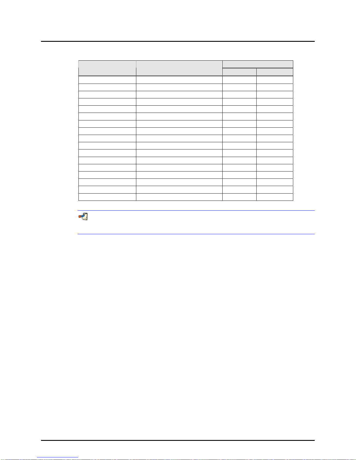
There are two different AFMETCAL configurations. One is the basic configuration. The other is the
calibration exchange system. Their differences are summarized below in Section 1.1.1. Table 1 lists the
specific components included in each configuration.
the two system configurations
BASIC AFMETCAL CONFIGURATION
The basic configuration includes a molbox, molstics and five molblocs to handle flows up to 40 slm. COMPASS for molbox software,
metering valve kits and the AFMETCAL Configuration Kit are also included in the basic configuration. This is the system
configuration which will be in regular use in the PMEL labs, and is specifically defined by NSN 6680-01-466-2062.
CALIBRATION EXCHANGE SYSTEM
This system is intended for delivery to AFMETCAL for temporary use at the various PMELs while each PMEL’s system is being
serviced or recalibrated. The exchange system is identical to the basic configuration above with two exceptions:
•The exchange system is delivered with CalTool software instead of COMPASS software to provide AFMETCAL with the
ability to recalibrate molblocs.
•Two custom shipping containers are included to facilitate the shipping of the exchange and PMEL systems back and forth for
recalibration.

MOLBLOC/MOLBOX LOW MASS FLOW CALIBRATION SYSTEM AFMETCAL
CONFIGURATIONS
INSTALLATION AND OPERATION MANUAL SUPPLEMENT
©2000-2008 DH Instruments, a Fluke Company Page 2
Table 1. Components List for AFMETCAL Configuration Systems
QUANTITIES
DHI PART NO. DESCRIPTION BASIC EXCHANGE
401265 molbox1 Terminal 1 1
3069609 (401182) 10 (1E1) sccm molbloc 1 1
3069611 (401183) 50 (5E1) sccm molbloc 1 1
3069648 (401198) 500 (5E2) sccm molbloc 1 1
3069037 (400483) 5 (5E3) slm molbloc 1 1
3069524 (401042) 30 (3E4) slm molbloc 1 1
3069773 (401318) Dual Low Flow molstic 1 1
3069712 (401244) Single Mid Flow molstic 1 1
3069764 (401317) Dual Mid molstic 1 1
3069786 (401319) Low Flow Metering Valve Kit 4 4
3069799 (401320) Mid/high Flow Metering Valve Kit 1 1
3350751 (401578) AF Config Mass Flow Kit 1 1
FAM0003 RPM3-A0100b Pressure Monitor 1 1
2758335 (100847) RS232 Cable 1 1
3069666 (401211) COMPASS Software Ver. 4.0 1
3119808 (102848) CalTool Software 1
NPN Custom Shipping Container 2
This manual is a supplement to the molbox1 and COMPASS for molbox manuals. For molbox1 system
specifications, refer to Specifications section in the molbox1 molbloc Terminal (Ver. 5.00 and higher) Operation
and Maintenance Manual.

MOLBLOC/MOLBOX™ LOW MASS FLOW CALIBRATION SYSTEM AFMETCAL
CONFIGURATIONS
INSTALLATION AND OPERATION MANUAL SUPPLEMENT
Page 3 ©2000-2008 DH Instruments, a Fluke Company
Installation
UNPACKING AND INSPECTION
Removing From Packaging
All molbloc/molbox system components and accessories are delivered in corrugated containers with custom inserts or foam to hold
them in place. They are also enclosed in protective plastic bags within the containers.
Remove the components from the shipping containers and remove each element from its protective plastic bag. Retain the boxes
and inserts for possible reuse.
Inspecting Contents
Use Table 1 to determine which components are included in your system. Descriptions of the components’ packaging and
accessories are below. Check that all items are present and have NO visible damage.
molbox1
molbox1 is delivered with caps installed over the pressure connections and
communications ports on the rear panel. A piece of cellophane protects the front
panel and may be removed. The molbox1 accessory kit is placed inside the box
with molbox1. The Metering Valve Kits (see Section 2.1.2.6) and the AFMETCAL
Configuration Kit (see Section 2.1.2.7) may also be placed in this box. The
following items should be present in the molbox1 accessory kit:
•molbox1 molbloc Terminal (Ver. 5.00 and higher) Operation and
Maintenance Manual
•molbox1 Calibration Certificate
•Power Cord
•Four molbloc to molbox1 Pneumatic Lines with Quick Connectors
•Two molbloc to molbox1 Electrical Connection Cables
•molTools Utility Software Disk
•COMPASS for molbox for Windows Demo Version Software Disks
•Four Rubber Feet Caps

MOLBLOC/MOLBOX LOW MASS FLOW CALIBRATION SYSTEM AFMETCAL
CONFIGURATIONS
INSTALLATION AND OPERATION MANUAL SUPPLEMENT
©2000-2008 DH Instruments, a Fluke Company Page 4
COMPASS FOR molbox SOFTWARE
A COMPASS for molbox software installation CD is secured inside the COMPASS
for molbox User’s Manual Version 4.00. The CD may have DHI product literature
and other support software stored on it in addition to the COMPASS for molbox
installation program. The COMPASS manual is typically placed with other system
manuals inside the box with molbox1.
AFMETCAL systems include COMPASS for molbox software version 4.0 (AF CPIN 88M-MOLBOX1AF-T001-
00A)
CALTOOL SOFTWARE
For the “calibration exchange system” configuration, CalTool for molbox is included
in place of COMPASS. It is on 3.5 in. floppy disks or a CD secured inside the back
cover of its manual.
molblocs
molblocs are shipped and stored in hard cases with sliding covers. The cases are
shipped inside cardboard boxes holding two molblocs each. There is a recessed
square on the front of the hard cases on which to apply the molbloc’s calibration
sticker if you desire. Calibration stickers are delivered with each calibration
certificate.
molbloc end fittings, pneumatic pressure quick connectors and communication ports
are capped for protection and cleanliness. Each molbloc has a black label on one side
listing the molbloc’s part number, serial number and ordering description. There is a
silver label on the other side listing the molbloc’s usable pressure and flow ranges and
indicating correct flow direction.
Four Viton O-rings and general molbloc mounting instructions are sealed in a bag
with each molbloc case. The Viton O-rings should be used in the VCR fittings when
mounting molblocs in molstics (see molstic Installation Instructions).
AFMETCAL configuration molblocs’ usable flow ranges differ from their nominal ranges due to the high
pressure calibrations performed on them. Both the operating pressure and flow range listed on each
molbloc’s silver label must be observed to ensure accurate flow measurements. See Section 3.1 for
explanation of molbloc operating pressure and usable flow range.

MOLBLOC/MOLBOX™ LOW MASS FLOW CALIBRATION SYSTEM AFMETCAL
CONFIGURATIONS
INSTALLATION AND OPERATION MANUAL SUPPLEMENT
Page 5 ©2000-2008 DH Instruments, a Fluke Company
molstics
molstics are packaged in long corrugated boxes surrounded by protective foam.
Accessory kits are packaged with the molstics and include Viton O-rings,
and installation instructions. Low flow molstic accessory kits also include a filler rod
which can be inserted in the VCR close coupling fitting at the molbloc’s outlet.
The filler is used to reduce dead volume between the molbloc and DUT to help
stabilize pressure when measuring very low flows (see molstic installation
instruction sheet). In systems where there is already significant volume from tubing,
the rod will not have much effect.
Both low and mid flow molstics are delivered with cradles to fit small
molblocs installed. The cradles on the single mid flow molstic need to be replaced
with the large molbloc cradles to fit the larger 30 slm (3E4) molbloc. All of the
molstic parts downstream of the cradles also need to be moved further downstream
to accommodate the 30 slm (3E4) molbloc’s greater length. The molstic base has
pre-drilled holes for each standard bracket and cradle in both positions (see the molstic
installation instructions).
METERING VALVE KITS
Metering valve kits are made up of several items including the metering valve, a valve
bracket and panel mounting nut, a coupling bracket and grommet, a VCR close
coupling union, two Viton O-rings and Allen screws. Each item in the kit is
packaged in a plastic bag. These kits are to be mounted on the downstream end of
each molstic channel.
Four low flow metering valve kits and one mid/high flow metering valve kit are
delivered. Mount the low flow metering valve kits on the dual low flow and dual mid
flow molstics. Mount the mid/hi flow metering valve kit on the single mid flow
molstic. The manufacturer’s part number written on each metering valve’s body
differentiates the low flow valves from the mid/high flow valve. The low flow valve
is SS-4BMG-VCR. The mid/high flow valve is SS-4BMRG-VCR. See Section
2.1.2.6 for specific mounting instructions for the metering valve kits.
Never forcefully tighten the molstic metering valves. They are not designed for positive shut-off, only flow
control.

MOLBLOC/MOLBOX LOW MASS FLOW CALIBRATION SYSTEM AFMETCAL
CONFIGURATIONS
INSTALLATION AND OPERATION MANUAL SUPPLEMENT
©2000-2008 DH Instruments, a Fluke Company Page 6
AFMETCAL LOW MASS FLOW SYSTEM CONFIGURATION KIT
The AFMETCAL Configuration Kit is contained in a single plastic bag and includes
each of the parts listed in Table 2.
Table 2. Parts List for AFMETCAL Configuration Mass Flow Kit P/N 401578
QUANTITY DHI PART NO. DESCRIPTION
5 3138039 (102821) Male VCR Nut
5 3136739 (102454) VCR to 4T Tube Adaptor
8 3132930 (100247) 4T Swage Nut
8 3132948 (100248) 4T Swage Front Ferrule
8 3132953 (100249) 4T Swage Rear Ferrule
2 3068350 (100109) 1/4 in. NPT M to Swage Adaptor
6 3372499 (102822) Swage Male Union
4 3328885 (102664) AN4 F to Swage Adaptor
2 3372514 (102824) Back Pressure Regulator
2 3137757 (102727) Regulator Panel Mounting Nut
2 3372506 (102823) Back Pressure Gauge
2 3232378 (101450-Z) 20 in. (50 cm) PFA Tube, 1/4 in. OD
2 3232378 (101450-Z) 6 in. (15 cm) PFA Tube, 1/4 in. OD
1 3375667 (550110) Manual, AFMETCAL Configurations
1 3372523 (102849) VCR Plug
1 2758335 (100847) RS232 Cable
CUSTOM SHIPPING CONTAINERS
The custom shipping containers are inside a corrugated box. No equipment is
delivered inside the containers. Both containers have custom foam cutouts to hold
up to four molblocs, one molbox1, and calibration documents.
RPM3
RPM3 is delivered with plugs installed in the pressure ports and caps over the
communications ports on the rear panel. Cellophane protection also covers the front
panel display. RPM3 is packaged with the RPM3 Operation and Maintenance
Manual and a power cord. An RS232 cable is included in the AFMETCAL
configuration system for PC communication with the RPM3, but it may be packaged
with the other accessories.

MOLBLOC/MOLBOX™ LOW MASS FLOW CALIBRATION SYSTEM AFMETCAL
CONFIGURATIONS
INSTALLATION AND OPERATION MANUAL SUPPLEMENT
Page 7 ©2000-2008 DH Instruments, a Fluke Company
general hardware setup
Site requirements
AFMETCAL configuration systems require a bench space that is at least 4 feet (1.3 m) long to arrange the molstic, device under test
(DUT) and back pressure regulator in series. It is often convenient to locate molbox on a shelf above these components if one is
available. Otherwise, it can be placed behind or beside the molstic on the bench. molbox’s front feet can be extended so that the unit
can be inclined slightly for easier viewing. The allowable distance between molbox1 and the molblocs is limited by the 3 feet (1 m)
long pneumatic tubes that connect them. The computer interface should be located nearby to allow convenient data entry. See
“Installation” in the molbox1 molbloc Terminal (Ver. 5.00 and higher) Operation and Maintenance Manual for other site
requirements and connection instructions.
installation of metering valve kits
Install the metering valve kits on each molstic channel as shown in Figure 1. The single mid flow molstic needs to be configured for
the large 30 slm (3E4) molbloc prior to installing the metering valve. The metering valve is inserted into its bracket leaving the panel
mounting nut loose. The metering valve bracket is attached to the downstream end of the molstic by fastening the Allen screws into
pre-drilled holes on the molstic. An arrow on the metering valve body indicates the proper flow direction. The male VCR fitting on
the metering valve inlet connects with the VCR close coupling fitting to the molbloc. Install the bottom half of the two piece
coupling bracket onto the molstic downstream of the metering valve. The VCR close coupling fitting is connected to the outlet of the
metering valve and is supported by the coupling bracket in the rubber grommet. Use a Viton O-ring in each VCR connection.
The manufacturer’s part number written on each metering valve’s body differentiates the low flow kits from the
mid/high flow kit. The low flow valve is SS-4BMG-VCR. The mid/high flow valve is SS-4BMRG-VCR.
install nuts and ferrules on swage tube parts
Numerical references refer to Figure 2.
Install the 4T Swage (Swagelok or equivalent) nuts and ferrules onto adaptor and tubes as follows:
•VCR tube adaptor (1): Slide male VCR nut on one side and swage nut and ferrules on the other.
•20 in. (50 cm) 4T (8): Swage nuts and ferrules on both ends.
•6 in. (15 cm) 4T (3): Swage nuts and ferrules on both ends.
Extra nuts and ferrules are included which can be kept as spares.

MOLBLOC/MOLBOX LOW MASS FLOW CALIBRATION SYSTEM AFMETCAL
CONFIGURATIONS
INSTALLATION AND OPERATION MANUAL SUPPLEMENT
©2000-2008 DH Instruments, a Fluke Company Page 8
installation of MOLBLOCS
molblocs are mounted in the cradles on the molstic(s). The 10 sccm (1E1) and 50 sccm (5E1) molblocs are mounted in the dual low
flow molstic, the 500 sccm (5E2) and 5 slm (5E3) molblocs are mounted in the dual mid flow molstic, and the 30 slm (3E4) molbloc
is mounted in the single mid flow molstic. molblocs are easily swapped into and out of a molstic when necessary (see molstic
instruction sheet).
Install the molblocs with the arrow on the silver sticker pointing in the direction of the flow. Be sure to use the Viton O-rings
provided when connecting the molbloc VCR end fittings (see molstic instruction sheet). When using molstics with metering valve
kits installed, it is easiest to install molblocs by connecting the downstream fitting first, then inserting the upstream O-ring and
connecting the upstream fitting last. Store molblocs in their cases when not in use.
See molbox1 molbloc Terminal (Ver. 5.00 and higher) Operation and Maintenance Manual (Initial Setup) for instructions on making
proper connections between molblocs and molbox1.
arrangement of flow path components
A. Filter E. Metering Valve
B. molstic Pressure Regulator F. Device Under Test (DUT)
C. Shut Off Valve G. Back Pressure Regulator
D. molbloc (and Gauge)
Figure 1. Arrangement of Flow Path Components

MOLBLOC/MOLBOX™ LOW MASS FLOW CALIBRATION SYSTEM AFMETCAL
CONFIGURATIONS
INSTALLATION AND OPERATION MANUAL SUPPLEMENT
Page 9 ©2000-2008 DH Instruments, a Fluke Company
Figures 1 and 2 show the system positioned so that the gas inlet is on the right side and the flow direction is to the left.
The standard arrangement is for the back pressure regulator (if it is needed) to sit freely on the bench. A regulator panel mounting
nut and gauge mounting U-clamp and bezel are supplied in the AFMETCAL Configuration Kit in case you wish to mount these
components on the bench or into a bracket. If you do mount them, keep in mind that the tubing length leading to the regulator
should be minimized to reduce flow and pressure instability.
It is helpful to have a moveable vice or similar device to hold the DUT in the proper orientation during calibration.
1. VCR Tube Adaptor 6. AN4 to Swage Adaptor
2. Swage Male Union 7. Swage Male Union
3. 6 in. (15 cm) PFA Tube 8. 20 in. (50 cm) PFA Tube
4. Swage Male Union 9. 4 NPT M to Swage Adaptor
5. AN4 to Swage Adaptor
Figure 2. AFMETCAL Kit Downstream of molstic
Figure 2 shows the general setup for the portion of the system downstream of the molstic. Since DUT fittings, shapes and pressure
requirements will vary, the exact setup will also vary. Figure 2 includes each of the fittings that are supplied in the AFMETCAL
Configuration Kit. A description of which fittings can be omitted for each application is outlined below.
The lengths of the PFA tubes (3, 8) are chosen to accommodate likely positions of DUT ports and the height difference between the
bench surface and molbloc platform. For some DUTs the tubes may be selected differently than shown in Figure 2. Since enough
fittings are supplied in the AFMETCAL Configuration Kit to assemble two complete flow channel setups, duplicate tubes can be
used to provide different lengths.
Whenever possible, tubing lengths between flow components (molbloc, DUT, back pressure regulator) should be minimized,
especially for lower flows. For example, if the DUT outlet port is not elevated like the one on the rotameter in Figure 1 and Figure 2,
then a shorter tube can be substituted for the 20 in. tube (8). Also, in some cases, the DUT’s size and weight may allow it to be
supported directly by adaptors downstream of the molstic and the 6 in. tube (3) can be omitted as described below.

MOLBLOC/MOLBOX LOW MASS FLOW CALIBRATION SYSTEM AFMETCAL
CONFIGURATIONS
INSTALLATION AND OPERATION MANUAL SUPPLEMENT
©2000-2008 DH Instruments, a Fluke Company Page 10
DUTS WITH AN FITTINGS
If the DUT can be supported directly from the molstic outlet fittings, then union (2)
and tube (3) can be omitted.
DUTS CALIBRATED WITH BACK PRESSURE
All fittings are connected as shown in Figure 2.
DUTS CALIBRATED WITHOUT BACK PRESSURE
(AT ATMOSPHERIC PRESSURE)
Fittings 6, 7 and 9, and tube 8 and the back pressure regulator can be omitted.
The DUT exhausts directly to atmosphere.
DUTS WITH SWAGE FITTINGS
If the DUT can be supported directly from the molstic outlet fittings, then union (2)
and tube (3) can be omitted.
DUTS CALIBRATED WITH BACK PRESSURE
Since adapting to AN4 is not necessary, fittings 4, 5, 6 and 7 can be omitted.
The 20 in. tube (8) is connected directly to the DUT’s outlet.
DUTS CALIBRATED WITHOUT BACK PRESSURE
(AT ATMOSPHERIC PRESSURE)
Fittings 4, 5, 6, 7 and 9, and tube 8 and the back pressure regulator are all omitted.
CONNECTIONS FOR DUT PRESSURE AND TEMPERATURE MEASUREMENT
Some kinds of DUTs require that flow corrections are made based on the density of
the gas flowing through the DUT during calibration. The density correction is made
from knowledge of the pressure and temperature of the gas as measured near
the DUT. The measurements of pressure and temperature at the molbloc which are
displayed on the molbox and/or COMPASS will not typically be accurate estimates
of the pressure and temperature at the DUT, since the expansion of the gas through
the metering valve can change both the pressure and temperature.
An RPM3-A0100b reference pressure monitor is included in the AFMETCAL
Configuration System to provide accurate DUT pressure measurement. A small back
pressure gauge is also included in the AFMETCAL Configuration Kit, but it will not
generally be accurate enough for DUT pressure measurement and is intended only
for reference indication. Pressure may be read from the RPM3 visually from the
front panel or remotely through a computer connected to it. (See Section 1.1.4 of
this manual, the COMPASS for molbox User’s Manual Version 4.00 and the RPM3
Operation and Maintenance Manual for instructions on operating RPM3 and reading
its pressure measurements via remote interface.)

MOLBLOC/MOLBOX™ LOW MASS FLOW CALIBRATION SYSTEM AFMETCAL
CONFIGURATIONS
INSTALLATION AND OPERATION MANUAL SUPPLEMENT
Page 11 ©2000-2008 DH Instruments, a Fluke Company
The RPM3 test port must be pneumatically connected to the flow path at the point
where the pressure is to be measured. Whether the pressure and temperature need to
be measured at the inlet or outlet of the DUT, or simply estimated from some
measurement of surrounding pressure and temperature, depends on Air Force
procedures and the type of DUT being calibrated. For instance, fittings 4 or 7 in
Figure 2 may be replaced by tees or other fittings which allow the RPM3 and a
temperature measuring device to be connected to and inserted in to the flow path.
Frequently, pressure is measured at the outlet of the DUT, which is open to
atmosphere when no DUT back pressure is required. In this case, the RPM3 can
also be left open to atmosphere to effectively measure the outlet pressure of the
DUT. When back pressure is to be applied to the DUT and measured, the RPM3
can either be pneumatically connected to the gauge port of the back pressure
regulator or connected to a tee in place of fitting 7 as described above.
Temperature is usually measured near the same location that pressure is measured.
The temperature measurement probe may create a flow restriction where it is inserted
into the flow path and create a pressure drop which can affect the DUT
pressure measurement. Make sure to either position the pressure measurement
connection closer to the DUT than the temperature measurement connection, or
avoid a temperature measurement connection that is significantly restrictive to flow.
Also, when the temperature and pressure devices are connected between the molbloc
and the DUT, care must be taken to make a leak-free connection.
Figure 3 shows an example of temperature and pressure connections made at the
outlet of the DUT, when back pressure is applied to the DUT.
Figure 3. Connection of RPM3 and Temperature Measurement Device
for DUT with Back Pressure
TEMPERATURE
F
1
FLOW DIRECTION
2
4
53
molstic
REFERENCEPRESSUREMONITOR
8
9
G
6
MEASUREMENT DEVICE

MOLBLOC/MOLBOX LOW MASS FLOW CALIBRATION SYSTEM AFMETCAL
CONFIGURATIONS
INSTALLATION AND OPERATION MANUAL SUPPLEMENT
©2000-2008 DH Instruments, a Fluke Company Page 12
N
NO
OT
TE
ES
S
This manual suits for next models
1
Table of contents