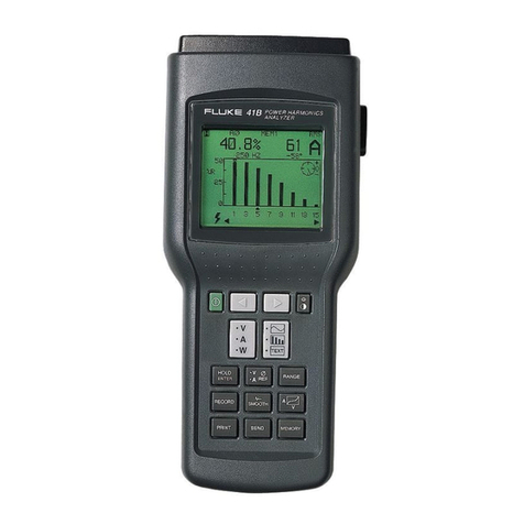
Fluke PM6681 User manual

Timer/Counter/
Analyzers
PM6681, PM6681R &PM6681R/676/AF
Service Manual

4822 872 20116
June 2003 Second Edition
Fluke grants permission for the U. S. Government to reproduce copies ofthis manual, on the condition that the legend “Reproduced with Permis-
sion” be legibly displayed on the copies. This material is not for resale. It is limited to Government use only and cannot be copied for any other
purpose.
II

GENERAL INFORMATION
This manual contains directions for use that apply to anumber ofmodels. In order to simplify references to certain models, the follow-
ing designation system is used throughout the manual:
PM6681 stands for PM6681, PM6681R and PM6681R/676/AF
PM668 1Rstands for PM6681Rand PM6681R/676/AF
The PM6681R/676/AF is amodel supplied with the following features:
-PM6681R base model
-Prescaler PM9624 (2.7 GHz)
-Rackmount kit PM9622
-Reference output option PM9671B
Refer to the respective type nunibers in the Operators Manual for specifications and other infomiation not found in this manual.
New options and deviations from the original design are collectively treated in Chapter 9, Appendix. Below is asummary of the
changes:
Unit 1
The main printed-circuit board (Unit 1) has recently been redesigned due to obsolescence ofanumber of integrated circuits. Designa-
tions found in circuit descriptions, schematic diagrams and parts lists in the first eight chapters refer to the original design. The func-
tional descriptions are correct on the whole, ifyou make afew substitutions. Anew set of schematic diagrams and anew replacement
parts list are added in Chapter 9, Appendix.
-Instruments having serial numbers >784919 belong to the new generation.
-The model PM6681R/676/AF has only been produced with the new Unit 1board, so the serial number is irrelevant.
Model PM6681R
The model PM6681R introduces an ultra-stable rubidium atomic clock reference.
Option PM9671B
Reference output unit offering six buffered 1Vrms outputs with four different standard frequencies: 3x10 MHz, 1x5 MHz, 1xl MDHz
and 1X0.1 MHz.
New OCXOs
The PM9691 has been redesigned, and aversion with very high stability ,the PM9692, has been introduced.
Ill

This page is intentionaliy ieft biank.
IV

Contents
1Safety Instructions
Caution and Warning Statements 1-2
Grounding 1-2
Disposal of Hazardous Materials 1-2
Line Voltage 1-2
2Performance Check
General Information 2-2
Required Test Equipment 2-2
Preparations 2-2
Front Panel Controls 2-2
Power-On Test 2-2
Internal Self-Tests 2-2
Keyboard Test 2-3
Short Form Specification Test 2-4
Sensitivity and Frequency Range 2-4
Check VMAXA/MIN 2-4
Trigger Indicators and Controls 2-4
Trigger level check 2-4
Reference Oscillators 2-5
Resolution Test 2-5
Rear Input/Output. 2-5
10 MHz OUT 2-5
GATE OPEN Output 2-5
REFERENCE IN 2-5
EXT ARM input 2-6
TRIG LEVEL A&B Outputs 2-6
Probe Comp View 2-6
Measuring Functions 2-6
Check on HOLD OFF function 2-7
Options 2-7
Check on Prescalers 2-7
PM 6681 Performance Check Report B-1
3Disassembly
Removing the Cover. 3-2
Reinstalling the Cover 3-2
Fan 3-3
PM 9621 ,PM 9624 or PM 9625 HF Input .......... 3-3
PM 9678B TCXO 3-3
PM 9690 or PM 9691 Oven Oscillator 3-4
Reinstalling the Battery 3-4
Exchange Procedure 3-4
4
Circuit Descriptions
Block Diagram Description 4-2
General 4-2
Hardware Functional Description 4-4
Front Unit 4-4
LCD Drivers 4-4
Keyboard 4-4
Main Board 4-5
Input Amplifier A4-5
Input Amplifier B4-8
Calibration Circuits 4-8
Trigger Level Circuits 4-9
Power Supply 4-10
Counter Circuits 4-12
Oscillator Circuits 4-14
Logical Circuits 4-16
GPIB Interface 4-18
Analog Output 4-18
Rear Panel Unit. 4-19
Optional Units 4-20
HF Inputs 4-20
Test Routines 4-23
Test Routines via AUX MENU Key 4-23
Power-On Tests 4-23
5
Repair
Preventive Maintenance 5-2
Calibration 5-2
Oscillators 5-2
Battery Replacement 5-3
Troubleshooting 5-4
General 5-4
Quick Troubleshooting 5-4
Where to Start 5-4
Logical Levels 5-4
Required Test Equipment 5-4
Operating Conditions 5-4
introduction 5-4
Running Test Programs 5-5
Troubleshooting Tree 5-5
Power Supply (Functional Level 1) 5-6
Oscillator (Functional Level 2) 5-7
Microcontroller (Functional Level 3) 5-8
Microcomputer Kernel (Functional Level 4a) 5-9
Microcomputer Kernel (Functional Level 4b) 5-9
V

Internal Control Signals and Display
(Functional Level 5a) 5-11
Internal Control Signals and Display
(Functional Level 5b) 5-12
Keyboard (Functional Level 6) 5-12
Measuring Logic (Functional Level 7) 5-13
Trigger Level DAC’s (Functional
Level 8) 5-14
Input Amplifier (Functional Level 9) 5-16
GPIB interface and Analog output
(Functional Level 10) 5-18
Safety Inspection and Test After Repair 5-19
General Directives .5-19
Safety Components 5-19
Check the Protective Ground Connection 5-19
6
Calibration Adjustments
Introduction. 6-2
Required Test Equipment 6-2
Preparation 6-2
Power Supply 6-2
Crystal Oscillators 6-3
16 MHz Oscillator 6-3
External Reference Input Multiplier 6-3
Standard Osciilator 6-3
100 MHz Frequency Multiplier 6-3
Optional TCXO, PM 9678B 6-4
Optional Oven Oscillators, PM 9690 and PM 9691 . . 6-4
Interpolator 6-5
Input Amplifier 6-6
Step Response 6-6
Channel A6-6
Channel B6-6
IX Attenuator channel A6-6
10X Attenuator channel A6-7
IX Attenuator channel B6-7
10X Attenuator channel B6-7
Sensitivity 6-7
Trigger Levels 6-7
Analog output 6-8
1.3 GHz HF-input, PM 9621 6-9
2.7 GHz HF-input, PM 9624 6-9
4.2 GHz HF-input, PM 9625B 6-10
4.5 GHz HF-input, PM 9625 6-10
7Replacement Parts
Introduction 7-2
Standard Parts 7-2
Special Parts 7-2
Mechanical Parts 7-3
Main Board 7-5
Front board 7-16
PM 9621........... 7-17
PM 9678B 7-19
8Schematic Diagrams
How to Read the Diagrams 8-2
Signals 8-2
Colored Areas 8-2
Circuit Symbols 8-2
Resistors, Capacitors, Diodes, Transistors and
Other Components 8-2
Component Numbers 8-2
9Appendix
How to Replace Surface Mounted Devices 9-2
Electrostatic discharge 9-3
Glossary 9-3
New Unit 19-4
Replacement Parts 9-4
Schematic Diagrams 9-11
Model PM6681R 9-25
OCXO Range Extended 9-27
Option PM9671B. 9-29
Replacement Parts 9-29
Schematic Diagrams 9-31
10
Index
VI

Chapter 1
Safety Instructions

WARNING: These servicing instructions are for
use by qualified personnel only. To reduce
the risk of electric shock, do not perform
any servicing other than that specified in
the Operating Manual unless you are fully
qualified to do so.
Authorized service and calibration of this instrument is avai-
lable worldv^ide. Alist of service centers is printed on the
last page of this manual.
Read this chapter carefully before you check, adjust or re-
pair an instrument
When the instrument is brought from acold to a
warm environment, condensation may cause haz-
ardous conditions. Therefore, ensure that the grounding re-
quirements are strictly met
Power extension cables must always have aprotective
ground conductor.
Indicates that the operator should consult the manual.
WARNING: Any interruption of the protecti-
ve ground conductor inside or outside the
instrument, or disconnection of the protec-
tive ground terminal, is likely to make the in-
strument dangerous. Do not Intentionally
disrupt the protective grounding.
Caution and Warning Statements
You will find specific warning and caution statements whe-
re necessary throughout the manual.
CAUTION: Indicates where incorrect operating
procedures can cause damage to, or de-
struction of, equipment or other property.
WARNING: Indicates apotential danger that re-
quires correct procedures or practices in
order to prevent personal injury.
This Timer/Counter has been designed and tested in ac-
cordance with safety class 1requirements for Electronic
Measuring Apparatus of lEC publication 1010-1, and CSA
C22.2 No.231, and has been supplied in asafe condition.
This manual contains information and warnings that should
be followed by the user and the service technician to ensu-
re safe operation and repair in order to keep the instru-
ment in asafe condition.
WARNING: The opening of covers or removal
of parts, except those to which access can
be gained by hand, is likely to expose live
parts and accessible terminals which can
cause death.
The instrument must be disconnected from all voltage sour-
ces before it is opened. Remember that the capacitors insi-
de the instrument retain their charge even if the instrument
has been disconnected from all voltage sources.
Grounding
This instrument is connected to ground via asealed three-
core power cable, which must be plugged into socket out-
lets with protective ground contacts. No other method of
grounding is permitted for this instrument.
The ground symbol on the rear panel indicates where the
protective ground lead is connected inside the instrument.
Never remove or loosen this screw.
Disposal of Hazardous Materiais
WARNING: Disposal of lithium batteries requi-
res speciai attention. Do not expose the
batteries to heat or put them under extensi-
ve pressure. These measures may cause
the batteries to explode.
Alithium battery is used to power the non volatile RAM in
this instrument. Our world suffers from pollution, so don’t
throw batteries into your wastebasket. Return used batte-
ries to your supplier or to the Philips or Fluke organization
in your country.
Line Voltage
The Timer/Counter can be powered by any voltage be-
tween 90 and 265 Vac without any range switching. This
makes it suitable for all nominal line voltages between 100
and 240 V.
•Replacing Components in Primary
Circuits
Components that are important for the safety of this instru-
ment may only be replaced by components obtained from
your local Philips or Fluke organization. After exchange of
the primary circuits, perform the safety inspection and
tests, as described in Chapter 5, "Repair".
•Fuses
This instrument is protected by an ordinary 1.6 Aslow
blow fuse mounted inside the instrument. NEVER replace
this fuse without first examining the Power Supply Unit.
1-2 Safety Instructions,

Chapter 2
Performance
Check

General Information
WARNING: Before turning on the instrument,
ensure that it has been installed In accord-
ance with the Installation Instructions
outlined in Chapter 1of the Operators Ma-
nual.
This performance procedure is intended to:
—Check the instrument’s specification.
—Be used for incoming inspection to determine the accept-
ability of newly purchased instruments and recently reca-
librated instruments.
—Check the necessity of re calibration after the specified
recalibration intervals.
NOTE: The procedure does not check every facet of the in-
strument’s calibration; rather, it is concerned primarily
with those parts of the instrument which are essential
for determining the function of the instrument
it is not necessary to remove the cover of the instrument to
perform this procedure.
If the test is started less than 20 minutes after turning on
the instrument, results may be out of specification, due to
insufficient warm-up time.
Required Test Equipment
Type of
instrument
Required
Specifications
Suggested
Instrument
LF Synthesizer Square;
Sine up to 2MHz PM5193
Digital Multimeter to 300 Vac &Vdc PM2518; Fluke 77
Power Splitter PM9584/02
T-piece PM9067; Y9107
Termination son PM9585; Y9103
Low pass filter 50 kHz PM9665B/01
Reference
oscillator
10MHz 1*i'10“^ for
01 to 04 oscillator
5MHz for
05 osc.
Philips counter
with calibrated
PM9691
PM 6685R *)
HF signal
generator
to 2.1 GHz for
PM9621, 5GHz
for PM9624 &25
Fluke 6062A
Wiltron 6717B-20
*)
Pulse Generator to 125 MHz PM5786B;PM5781
Oscilloscope with
probes
350 MHz PM3295
Power Supply min 40 Vdc PM2811/113,
PE1537; PE1542
BNC-cables 5to 7cables
Table 2-1 Recommended Test Equipment
*) This test equipment in needed if an option Is installed.
Preparations
Power up your instruments at least 20 minu-
tes before checking to let them reach normal
operating temperature. Failure to do so may
result in certain test steps not meeting equip-
ment specifications.
Front Panel Controls
Power-On Test
At power-on the timer/counter performs an automatic self-
test of the following:
-Microprocessor
-RAM
-ROM
-Measuring circuits
It also displays the GPIB address.
If there are any test failures, an error message is shown.
Internal Self-Tests
The built-in test programs from the power-on test can also
be activated from the front panel as follows:
-Enter the Auxiliary Menu by pressing AUX MENU.
-Select the test submenu by pressing SELECT up or
down.
-Enter the test menu by pressing the ENTER key.
Selections for internal self-tests are:
1TEST RO (ROM)
2TEST RA (RAM)
3TEST ASIC (Measuring Logic)
4TEST DISP (Display Test)
5TEST ALL (Test 1to 4in sequence)
s.B.B.aae.aaaQ-£ „m+im UMAX
SXMIN
Hz DI3PLR0LD MEAN
,SINGLE ST DEV
ENTER VMB.(OFI¥' AUX
FREQ AFREQC PER ARATIO A/B RATIO C/B PWIDTH ATIMEA-B PHASE A-B ARM ARM
TOTA-BMAN TOTAfUlB TOTAR BDUTY FA RISBFALLA VOLTA MAX/MIN STA+ STOf
REMOTE E>aREF RLTEH lEOMfl 0=1=1 A±TB =1= 150MQ COMA CHECK HOLD
SRQ LO BAT 10X DCAC BURST AID'O PRF DCAC 1DX OFF
Figure 2-1 Text on the display
-Use SELECT/SET to select TEST ALL, then press EN-
TER.
-If any fault is detected, an error message appears on the
display and the program halts.
-if no faults are detected, the program returns to measu-
ring mode.
2-2 Performance Cheeky General Information

Keyboard Test
This test verifies that the fimer/counfer responds when you
press any key. To check the function behind the keys, see
the tests further on in this chapter.
Press the keys as described in the left column and look on
the display for the text, as described in the second column.
Some keys change more text on the display than descri-
bed here. The display text mentioned here is the text most-
ly associated with the selected key.
NOTE: For the instrument to respond correctly, this test must
be carried out in sequence and you must start with the
Preset setting.
Key(s) Display Pass
/Fail
Note
STAND-BY Display Off Red LED
beside
the key
On
ON Backlight
on
PRESET preset Default
setting
EXT REF EXT REF
1Input A1
FILTER FILTER
5on/iMn 50 a
//\ \
AC/DC DC
AUTO 1X
1X/10X 10X
SETA 1,73 1.73 VEnter
ENTER
SWAP AOBA% B
IInput BII
//\ \
50Q/1MQ 50 Q
SETS 0.9
8+/- -0.98 VEnter
ENTER
AC/DC AC
1X/10X 10X
COMA COMA
HOLD OFF ON HOLD OFF
HOLD OFF SET HOf fti .
PRESET
II Other II
TIME 200“^ s
SELECT A500"* s
ENTER
HOLD DISPL HOLD
HOLD
SINGLE SINGLE
FUNCTION VOLTAmax/MIN
FUNCTION RISE/FALLA
FUNCTION VOLT AMAX/MIN
FUNCTION FREQ A
AUX MENU Addr .
Key(s) Display Pass
/Fail
Note
RESTART
START ARM Ar .Sta OFF
RESTART
STOP ARM Ar .StO OFF
RESTART
PRESET preset
CHECK 1000000000^ Start
counting
MATH
SELECT T
ENTER
Arith OFF
Arith ON
lOODOOOOOO^
K=
2
10
2
ENTER 2000000000^
kCounting
L=
Xn-1
ENTER
0 0
n-1
3000000000^
k
Counting
L= n-1
0ENTER 2000000000^
kCounting
L= Xo ENTER ^4000000000^
*Counting
L= 200 0000000*^
4EE 7ENTER 240 0000000*=’ Counting
M= .50 5
ENTER 4800000000^
*Counting
STAT Stat. OFF
ENTER 480 DOOOOOO*’ Counting
FUNCTION
(6 times)
TOT A-B MAN
TOT St/St Gate LED lit
MENU Displays all
available
functions,
processes and
input controls.
Selected items
are blinking.
PRESET kk Default
setting
Table 2-2 Keyboard test
*The LSD digit may vary.
** MENU is not disabled by setting DEFAULT, press menu
again.
Performance Check, Front Panel Controls 2-3 .

Short Form Specification Test
Sensitivity and Frequency Range
-Press the PRESET key to set the timer/counter in the
default setting.
“Seiect 50 Qinput impedance and Non AUTO, (X1).
“Connect asignal from aHF generator to aBNCpower split-
ter.
—Connect the power splitter to your counter and an oscillosco-
pe.
—Set input impedance to 50 Q, on the oscilloscope.
-Adjust the amplitude according to the following table.
Read the level on the oscilloscope. The timer/counter
should display the correct frequency.
Frequency Level Pass/Fail |
MHz mVpp dBm input
AInput
B
157 20 -21
50 57 20 -21
100 57 20 -21
200 85 30 -17 Chan-
lOOMHzi
250 113 40 -15
300 170 60 -11
Tabie 2-3 Sensitivity forA&B inputs at various frequencies
“Connect the signal to input B.
-Select 50 Oinput impedance and SWAP ABon the
counter.
-Repeat the above measurements for input B.
Check VMAX/VMiN
Check DAC for trigger level settings.
-Set your timer/counter in default setting by pressing
PRESET.
-Select DC coupling, 1input impedance and VOLT A
MAX/MIN, but do not connect any input signal.
-The counter should now indicate:
Vmax =0±0.004V and Vmin =0±0.004V.
-Connect a4.00 Vdc level to channel A, using an exter-
nal low pass filter on the input.
-The readings should be:
Vmax =4.000 ±0.044V, Vmin =4.000 ±0.044V.
-Change the DC level to 40V.
-The counter should indicate:
Vmax -40.0 ±0.84V, Vmin =40.0 ±0.84V.
-Repeat the measurement with inverted polarity.
-Press MATH and select (K*X+L)/M to change to Vpp
measurements.
-Press ENTER.
-Connect asinusoidal signal to channel Awith an ampli-
tude 4.00 Vpp and afrequency of 100 kHz.
“The indication should be 4.00 ±0.244V.
-Change the amplitude to 18 Vpp.
-The display should read 18.0 ±1.84V.
-Select SWAP A4^ B, and connect the signal to channel
B. Repeat the measurements for Bas described above.
Trigger indicators and Controis
NOTE: This test must be performed in the sequence given.
-Press the PRESET key to set the Timer/ Counter in the
default setting.
“Select Non AUTO, XI attenuation, and 1MQ, input impe-
dance for channel A.
-Connect the following signal to channel A:
Sine, 10 kHz, 0.9 Vpp, and +0.50 Vdc-
-Verify that the three modes for the trigger indicator are
working properly by changing the trigger level:
-Press the SET Akey and enter 1via the keyboard,
then verify by pressing ENTER. Check the trigger indi-
cator according to Table 2-4.
-Press the SET Akey and enter -1 via the keyboard,
then verify by pressing ENTER. Check the trigger indi-
cator according to Table 2-4.
“Press the SET Akey and enter 0via the keyboard,
then verify by pressing ENTER. Check the trigger indi-
cator according to Table 2-4.
Manually
set trigger
level
Trigger
indicator
Pass/Fail
Input AInput B
+1 Voff
-1 Von
0.0 Vblinking
Table 2-4 Trigger indicator check
-Select SWAP AB, and AC coupling on channel B,
and repeat the exercise for channel B.
Trigger ievei check
-Deselect SWAP A4-^ B, connect the generator to chan-
nel Aand check the trigger settings and indicators accor-
ding to Table 2-5.
Trigger setting Trigger
indicator
Pass/Fail
Input AInput B
SET A=0Vblinking
DC coupling on
SETA= 0.7 Vblinking
50 £2 impedance off
SET A=0.2 Vblinking
AC coupling &
1M£2 Impedance blinking
XI 0Attenuation off
SETA= 0.0 Vblinking
XI Attenuation blinking
Table 2-5 Trigger ievei check
-Select A^B
“Connect the signal to channel B.
-Select AC coupling on channel B, and repeat the pre-
vious settings for channel B.
-Connect the signal to channel A.
-Only the trigger indicator for channel Ashould be blinking.
“Press COM A.
-Both indicators should be blinking.
-Connect the signal to channel B.
-No trigger indicator should be blinking.
2-4 Performance Check, Short Form Specification Test

Reference Oscillators
X-tal oscillators are affected by anumber of external condi-
tions like ambient temperature and supply voltage but also
by ageing. Therefore it is hard to give limits for the allowed
frequency deviation. The user himself must decide the li-
mits depending on his application, and recalibrate the oscii-
lator accordingiy. See the Preventive Maintenance chapter.
Oscillator Max
temperature
dependence
Max
ageing
month
Max
ageing year
Standard. 01 ±100 Hz ±5 Hz ±50 Hz
PM 9678B, 02 ±10 Hz ±1 Hz ±5 Hz
PM 9690, 04 ±0.15 Hz ±0.2 Hz ±1 Hz
PM 9691, 05 ±0.05 Hz ±0.1 Hz ±0.75 Hz
Table 2-6 Deviation (for PM 9690 and PM 9691 after
48 hours warm up time)
To check the accuracy of the oscillator you must have aca-
librated reference signal that is at least five times as stable
as the oscillator that you are testing, see the following ta-
ble. If you use anon 10 MHz reference, you can use the
mathematics in PM 6681 to multiply the reading.
-Set the counter to default settings by pressing PRESET.
“Connect the reference to input A
-Check the readout against the accuracy requirements of
your application.
•Acceptance Test
As an acceptance test the following table gives aworst case
figure after 30 minutes warm up time. All deviations that can
occur in ayear are added together.
Oscillator Frequency readout Suitable
reference
Pass
/Fail
Standard, 01 10.00000000 MHz
±150 Hz PM 9678B
PM 9678B, 02 10.00000000 MHz
±15 Hz PM 9690
PM 9690, 04 10.00000000 MHz
±2Hz PM 6685B
PM 9691, 05 10.00000000 MHz
±1Hz PM 6685B
Table 2-7 Acceptance test for oscillators
Resolution Test
-Connect apulse generator to apower splitter.
-Connect one side of the power splitter to the Ainput of
the counter via acoaxial cable.
-Connect the other side of the power splitter to the Bin-
put of the counter.
Settings for the pulse generator,
-Amplitude =1Vpp, (high level +1V and low level OV)
-Period approximately 1|lis
-Duration =approximately 50 ns
-Rise time 2ns
Settings for the timer/counter, after Preset:
-Function =Time A-B
-Single
—Press STAT key under PROCESS
—Press SELECT key until display show ’ST DEV’.
—Meas Time =50 ills
—Aand Binputs:
-50 Oinput impedance
-Non AUTO
-Trigger level =0.5V
-DC coupling
The result should be (std dev) <0.05'® s.
Rear Input/Output
10 MHz OUT
-Connect an oscilloscope to the 10 MHz output on the
rear of the counter. Use coaxial cable and 50 Q. termina-
tion.
-The output voltage is sine wave shaped and should be
above 500 mV rms (1 .4 Vp-p).
GATE OPEN Output
-Set your timer/counter in Default setting by pressing the
PRESET.
-Select CHECK, Non AUTO, and Meas Time =5ms.
~Connect the oscilloscope to the Gate Open output via a
coaxial cable. Set the oscilloscope to Ims/division.
-The Gate Monitor output should be apulse similar to the
Figure 2-2 .
1Mohm: 50 ohm:
>2.8V >1.4V
<0.4V <0.4V
Ims/div.
Figure 2-2 Signal on gate open output
REFERENCE IN
-Set the counter to Default Setting by pressing PRESET.
-Connect EXT REF out from another counter to input A.
-Connect a10 MHz ±100 Hz, 200 mV rms, (0.57 Vp-p)
signal to EXT REF IN at the rear, terminated with 50Q.
-Select Ext Ref.
-The display should show 10 MHz.
-Change the input frequency to 5, 2, and 1MHz respec-
tivly.
-The display should still show 10 MHz.
Performance Check, Rear Input/Output 2-5

EXTARM input
-Select non AUTO.
-Settings for pulse generator: single shot pulse, amplitude
TTL =0-2 Vpp, and duration =10 ns.
-Connect apulse generator to EXT ARM input.
-Press START ARM key.
-Press SELECT key until display shows ’POS’, confirm
with ENTER key three times.
-The counter does not measure.
-Apply one single pulse to EXT ARM input.
-The counter measures once and shows 10 MHz on the
display.
TRIG LEVEL A&B Outputs
-Press the PRESET key, to set the timer/counter in the
default setting.
-Connect avoltmeter to TRIG LEVEL A(B) OUT at the
rear.
-Set the Trigger Level (SET A/B) on the front to the follo-
wing values, and verify the voltmeter’s readout:
SET A(B) Readout Pass/Fail
Input AInput B
+5.00 V+5V±0.28V
-5.00 V-5V±0.28V
0.00 V0V±0.03V
Table 2-8 Trigger level outputs check
Probe Comp View
—Press the PRESET key to set the timer/counter in default
setting.
Figure 2-3 Adjustment of the counters probe.
“Select TIME A-B, non AUTO, XI attenuation and DC
coupling for both channels.
-Set the LF synthesizer to 2kHz square wave and 8Vpp
amplitude.
-Connect synthesizer to Input Avia aBNC-cable.
-Use an oscilloscope to check the signal at Probe Comp
View, at the rear. The square wave will have the same
step response and 4Vpp amplitude.
-Select XI 0attenuation.
-Check that the square wave is 2kHz and 0.4 Vpp.
-Repeat this test for channel B.
Measuring Functions
Preparation for Check of Measuring Function:
-Press the PRESET key, to set the timer/counter in the
default setting.
-Connect a10 MHz sine wave signal with 2.0 Vpp ampli-
tude to input A.
Select the following settings for the timer/counten
-50 £1 input impedance for Aand B
-Non AUTO
-COMA
-Check that the timer/counter performs the correct meas-
urement, by displaying the result as shown under the
"Display" column in Table 2-9.
Selected
Function
Action Display Pass/
Fail
FREQ A10 MHz
FREQC 3)
PER A100‘® s
RATIO A/B 10000000
Select
NEC SLOPE B10000000
RATIO C/B 00000000
PWIDTHA 50 000"® s''^
TIME A-B 50 000"®
PHASE A-B 180 or -180'’^
TOT A-B
MAN 0
Deselect
COMA 0
TOT
ST/STOP
counting
TOT
ST/STOP
stop counting
Select COM A0
TOT A
JX_TL B
1
TOT A
^B
1
Select
POS SLOPE B
0
DUTY FA 0500000
Select AUTO 0500000
RISE/FALL
A30000"® S2)
VOLT
MAX/MIN +100 0
-1 0 0 0V
Table 2-9 Measuring functions check
1) Value depends on the symmetry of the signal.
2) Exact value depends on input signal.
3) if an C-option is installed.
2-6 Performance Check, Measuring Functions

Check on HOLD OFF function “Verify that the counter counts correctly. (The last digit
will be unstable).
Press PRESET on the timer/counter.
Select the following settings for the timer/counten
-Press CHECK.
-Select PER A.
-The counter should show 10 s*.
-Select HOLD OFF.
-The counter should show 1s*.
-Set the Hold off time to 500"® s.
-The counter should show 500 s*.
*The LSD digits may vary.
Options
Check on Prescalers
To verify the specification of the HF inputs in the instru-
ment, perform the measurements below.
•PM 9621
Required Test Equipment Suggested instrument
HF signal generator Fluke 6062A
Table 2-10 Test equipment for 1.3 GHz HF-input
—Connect the output of the signal generator to the HF in-
put of the counter.
-Connect the 10 MHz REFERENCE OUT of the generator
to the REFERENCE IN at the rear panel of the counter.
Setting for the timer/counter after Preset.
-Function =FREQ C.
-EXT REF.
Figure 2-4 Connect the output of the signal generator
to the HF-input of the counter.
—Generate asine wave in accordance with the correspon-
ding table below.
Frequency Amplitude Pass/Fail
MHz mVpiv/ip; dBm
70-900 10 -27
-1100 15 -23
-1300 40 -15
Table 2-11 Sensitivity of PM 9621
•PM 9624, PM 9625B, or PM 9625
Required Test Equipment Suggested instrument
HF signal generator Wiltron 6717B-20
Table 2-12 Test equipment for 2.1, 4.2, and 4.5 GHz HF-in-
puts
-Connect the output of the signal generator to the HF in-
put of the counter.
“Connect the 10 MHz REFERENCE OUT of the generator
to the REFERENCE IN at the rear panel of the counter.
Setting for the timer/counter after Preset.
“Function =FREQ C.
-EXT REF.
-Generate asine wave in accordance with the correspon-
ding tables below.
Frequency Amplitude Pass/Fail
MHz mVpivict dBm
100-300 20 -21
-2500 10 -27
-2700 20 -21
Table 2-13 Sensitivity of PM 9624.
Frequency Amplitude Pass/Fail
MHz dBm
150-300 20 -21
-2200 10 -27
-3500 15 -23.5
-4200 25 -19
Table 2-14 Sensitivity of PM 9625B.
Frequency Amplitude Pass/Fall
MHz mVRMp; dBm
150-300 20 -21
-2500 10 -27
-3500 15 -23.5
-4200 25 -19
-4500 50 -13
Table 2-15 Sensitivity of PM 9625.
-Verify that the counter counts correctly. (The last digit
wili be unstable).
Performance Check, Check on HOLD OFF function 2-7

This page is intentionaily ieft blank.
2-8 Performance Check, Options

PM 6681 Performance Check
Report
(page 2-2)
l^il
/PRESET
SELECT A
ENTER
HOLD
:;^HOLD
WSINGLE
EUNCTldN^ I-
FUNCTION
VRESTART
PRESET
ENTER
STARTARfi/i
ggESpV^
iSTOPARWl'
RESTART
PRESET
CHECK
Other Preset
m. V-. ^:SiNGLE
WoLTAMk/m
VRfSE/FALLA
VOLTA MAX/MiN
FREQ A
Addr
?Arith OFF
ioO'D'OOOOOO^*
1D
2
1


»r;ir:T>«gger Level
Triaaer settinq 1Ik
1Jriqqen^ir
Input AiHicator:!^.;
SET A=0Vblinking
1
OCcouDiina
SETA= 0.7 Von
SlirridhS
SET A= 0.2 V
1MO Impedance
X10 Attenuation
SET A=0.0 Vblinking
X1 Attenuation
Inputs
SET B=0VaiiWk'iflffl
DC coupling
":biiiii®
50 nImpedance I'
b= o.2ViliW
AC coupling &
llwlO Impedance blmklngl
iSHi Attenuation olfl
ii- ‘-iiETB= 0.0 Vblinking
fe'. Attenuation :blinking 1
Reference Oscillators
:
Oscillator readout value
iStalidardi il0;t)0000000 tUlHz
fcjSiisO'iz
PIM 9678B
lilStft?
PM 9690,
04 10.00000d00 MH£|
PM 9691,
05 toopoodojiHi;
(page 2-5)
SET AfB)
id Level Outputs
sjpaga 2-6)
Readout fleasured
value Pass Fail
+Sjoov
-5.00 V
0.00 V
45V ±d.i§V
-5V40.28V
0V±30mV
l^iipov
-5.00 V
0.00 V
+5V10.28 V
-5V10.28 V
Probe Comp View
(page 2-6)
Attenuator
iff;
Oscilldsc0Mi:ldeiiui|d '
’1#ii:{
':;rekd6Ut-:iiS^ul
-Wa. .: V: :f;|.:v4iiiut A
X1
X10
X1
X10
2kHz. 4
2kHz, 0.4
3

This manual suits for next models
2
Other Fluke Measuring Instrument manuals

Fluke
Fluke 753 User manual

Fluke
Fluke 831 User manual

Fluke
Fluke 433 User manual

Fluke
Fluke 373 Instruction manual

Fluke
Fluke i410 User manual

Fluke
Fluke 633 QuickCHECK-T1 User manual

Fluke
Fluke BT520 User manual

Fluke
Fluke PG7607 User manual

Fluke
Fluke LinkSprinter 100 User manual

Fluke
Fluke 789 User manual

Fluke
Fluke i400s Use and care manual

Fluke
Fluke VR1710 User manual

Fluke
Fluke 971 User manual

Fluke
Fluke ASM-990 Series Instruction Manual

Fluke
Fluke 715 User manual

Fluke
Fluke 377 Use and care manual

Fluke
Fluke 985 User manual

Fluke
Fluke 323 User manual

Fluke
Fluke 433 Configuration guide

Fluke
Fluke 05-450 User manual