Fluke DATAPAQ Oven Tracker XL2 User manual

Oven
Tracker
®
XL2
USER MANUAL
Issue 1
MA5150A


Oven Tracker
®XL2
User Manual
for use with
Issue 1
Datapaq is the world’s leading manufacturer
of process temperature-monitoring
instrumentation. The company maintains
this leadership by continual development
of its advanced, easy-to-use Tracker systems.
DATAPAQ PART NO. MA5150A
Europe & Asia
Datapaq Ltd.
Lothbury House, Cambridge Technopark
Newmarket Road
Cambridge CB5 8PB
United Kingdom
Tel. +44-(0)1223-652400
Fax +44-(0)1223-652401
Email [email protected]
www.datapaq.com
North & South America
Datapaq, Inc.
3 Corporate Park Dr., Unit 1
Derry
NH 03038
USA
Tel. +1-603-537-2680
Fax +1-603-537-2685
Email [email protected]
www.datapaq.com

© Datapaq Ltd., Cambridge, UK 2009
All rights reserved
Datapaq Ltd. makes no representations or warranties of any kind
whatsoever with respect to the contents hereof and specifically
disclaims any implied warranties of merchantability or fitness for any
particular purpose. Datapaq Ltd. shall not be liable for errors
contained herein or for incidental or consequential damages in
connection with the furnishing, performance or use of the Datapaq
software, associated hardware or this material.
Datapaq Ltd. reserves the right to revise this publication from time to
time and to make changes to the content hereof without obligation to
notify any person of such revisions or changes.
Datapaq, the Datapaq logo and Oven Tracker are registered
trademarks of Datapaq. Microsoft and Windows are
registered trademarks of Microsoft Corporation.
Manual set in 10 pt Gill Sans.
User manuals are available in other languages;
contact Datapaq for details.
SAFETY WARNINGS
For safe use of Datapaq equipment, always:
•Take care to follow its supplied instructions.
•Observe any warning signs shown on the equipment itself.
Indicates potential hazard.
On Datapaq equipment this normally warns of high
temperature, but where you see the symbol you should
consult the manual for further explanation.
Warns of high temperatures.
Where this symbol appears on Datapaq equipment, the
surface of the equipment may be excessively hot (or
excessively cold) and may thus cause skin burns.

European
Union
Directives
The following product types
XL2 Thermocouple Data Logger
manufactured by Datapaq Ltd.
Lothbury House, Cambridge CB5 8PB, UK
comply with the requirements of European Union directives as
follows.
Directive 2004/108/EC Electromagnetic Compatibility (EMC)
Standards Applied
EN61326-1: 2006 – Group 1, Class B equipment (emissions section
only), and Industrial Location Immunity (immunity section only).
CFR47: 2007 Class A – Code of Federal Regulations: Part 15
Subpart B, Radio Frequency Devices, Unintentional Radiators.
RoHS Compliance Datapaq temperature monitoring equipment
is exempt from EU Directive 2002/95/EC (restriction of the use of
certain hazardous substances in electrical and electronic equipment)
under category 9 Monitoring and Control Instruments. This Datapaq
product nevertheless uses RoHS-compliant components and
manufacturing processes.
Conforms to relevant South Korean EMC Standards.
Electromagnetic Compatibility Applies to use in
Korea only. Class A Equipment (Industrial Broadcasting &
Communication Equipment). This product meets
requirements for industrial (Class A) electromagnetic
wave equipment and the seller or user should take notice
of it. This equipment is intended for use in business
environments and is not to be used in homes.

CONTENTS
9 Introduction
11 System Components
13 Insight Setup
13 Installing/Removing Insight
14 Communications Setup
17 XL2 Logger Specifications and Operation
19 Specifications
20 Logger LEDs
22 Dual Interface Block
23 Memory Capacity
23 Battery
26 Over-temperature Protection
26 Hardware Reset
27 Testing and Calibration
28 Disposal of Loggers
29 Thermal Protection – Barriers and Heatsinks
29 Aluminum Thermal Barriers
31 Stainless-steel Thermal Barriers
33 Selecting a Thermal Barrier
34 System Carrying Cases
35 Thermocouple Probes
35 Thermocouple Specifications
36 Thermocouple Cable Insulation
37 Thermocouple Types and Accessories
41 Working with Thermocouple Probes

45 Running a Temperature Profile
45 Overview
46 Resetting the Data Logger
50 Using SmartPaq
53 Installing the Logger in the Thermal Barrier, and Starting
the Logger
55 Placing the System in the Oven
55 Removing the System from the Oven
57 Downloading Data
60 Preparing the Data for Analysis
61 Logger Defaults and Details
63 Using Hardwired Telemetry
63 Running a Temperature Profile Using Hardwired
Telemetry
67 Troubleshooting
67 Logger Communications Problems
67 Logger Download Error Messages
67 Checking the Data
68 Logger Diagnostics
68 Datapaq Service Department
69 INDEX


OVEN TRACKER XL2 Introduction 9
Introduction
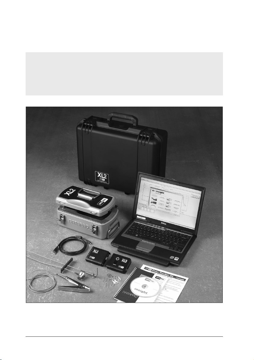
Datapaq Oven Tracker
®– incorporating Insight™software, and designed
specifically for use in the general coating and finishing industry – is a complete
system for monitoring the temperature profiles of products within your oven;
accurate data acquisition and powerful analysis techniques are combined with
flexibility and ease of use. The Oven Tracker system’s power and flexibility
make it a perfect tool for process temperature monitoring, from commissioning
and troubleshooting to process optimization, ensuring consistent quality of
product and maximum efficiency.
Current temperature characteristics can quickly be compared with previously
stored reference curves to detect operating abnormalities – and innovative
analysis techniques help in identifying problems, fine-tuning the process and
reducing running costs. A powerful and flexible printing option allows the user
to generate and customize reports, including any or all of the analysis results or
raw temperature data.
The basic Oven Tracker system hardware comprises:
•Data logger (including communications lead and charger).
•Thermal barrier.
•Thermocouple probes.
This manual contains information for all Oven Tracker users, from novice to
experienced. The chapters are arranged in logical order, explaining the Oven
Tracker system and the sequence of events in setting up and conducting a
temperature profile run. There is also guidance on setting up the Insight
software; complete information on using the software is contained in the online
Help system available when it is installed.
Insight Setup (p. 13) – Initial setup of the Insight software, and its use in
preparing the logger to obtain temperature-profile data and in downloading the
data after the run. The use of hardwired telemetry is also described.
XL2 Logger (p. 17) – The data logger’s specifications and basic operation.
Barriers and Heatsinks (p. 29) – Selection and use of the thermal-protection
system.
Thermocouple Probes (p. 35) – Choosing from the wide range Datapaq
probes available for different applications, and the methods for positioning and
attaching them.
Running a Temperature Profile (p. 45) – Readying the Tracker system for
the oven, and recovering it after the temperature-profile run.

Using Hardwired Telemetry (p. 63) – Monitoring conditions inside a batch
oven and watching a temperature profile develop in real time.
Troubleshooting (p. 67) – Lists software error messages and describes how
to test the data logger and probes.
For a rapid overview of the features of the XL2 logger and its step-by-step use with
the Oven Tracker system, see the Oven Tracker XL2 Quick
Reference Guide.
For full details on use of the Insight software, refer to the online Help system
available when the software is installed.
A typical standard Oven Tracker XL2 system.
10 Introduction OVEN TRACKER XL2

OVEN TRACKER XL2 Introduction 11
For use of the StenterPaq and CoilPaq systems, and for use of the XL logger
(including radio-telemetry), see the Oven Tracker User Manual (part no.
MA5000A).
System Components
A typical Oven Tracker XL2 system comprises:
•XL2 data logger (comprising MemoryPaq and Transducer Interface units),
with communications lead and charger (p. 17).
•Optional Dual Interface Block with additional Transducer Interface.
•Thermal barrier (p. 29).
•Thermocouple probes (p. 35).
•Insight Oven Tracker software.
•Oven Tracker XL2 User Manual.
•Oven Tracker XL2 Quick Reference Guide.

12 Introduction OVEN TRACKER XL2

OVEN TRACKER XL2 Insight Setup 13
Insight Setup
Before the logger is used for the first time, you must:
1. Install Insight software.
2. Establish communication between the logger and the computer/software.
Installing/Removing Insight
Datapaq Insight used with the XL2 logger requires the following minimum
computer specification.
•1 GHz processor.
•2 Gb RAM.
•Monitor resolution 1024 ×768, 256 colors.
•100 Mb free hard-disk space.
•DVD drive.
•1 free USB port.
•Microsoft Windows™ XP, Vista, 7, 8 or above.
•Microsoft Internet Explorer 4 or above.
The XL2 logger operates only with Datapaq Insight v.6.0 and above.
Installation
Ensure you are logged into Windows in Administrator mode.
For most systems, installation will start automatically on placing the Insight
DVD in the drive. (If installation does not start, click the Windows Start button
and select Run; browse to your DVD drive, and run Setup.exe.)
Follow the on-screen instructions. You will need your license number to hand,
which is to be found on:
•Your license agreement.
•The outside of the DVD case.
•The outside of the system packaging.
Insight’s link with the logger must also be made while Windows is in
Administrator mode, and it is thus best to do this now, as part of the Insight
installation: connect the logger to the PC and follow the procedure under

14 Insight Setup OVEN TRACKER XL2
‘Communications Setup’ (below). Once this has been done, an operator will be
able to use Insight with the logger connected to the PC without being in
Administrator mode.
Upgrading
It is not necessary to remove an existing version of the software before
installing a new one. Settings and data files used with the current installation
will be maintained.
Removal
From the Windows Start button menu, select Settings and then Control Panel.
Double-click Add/Remove Programs, select Datapaq Insight and click Add/
Remove.
Using the Software
Full details on using the Insight software are contained entirely within its online
Help system: access this by clicking Help, and then Contents, on Insight’s
main menu. Then, within Help, click on Contents headings and topics to expand
and read them.
You may also click the Help button in any dialog – or press the F1 key – to
bring up help information relevant to the task being performed.
For use of Insight to reset the logger, see p. 46.
For downloading data from the logger, see p. 57.
Communications Setup
After Insight has been installed, it is necessary to establish communication
between the data logger and the PC. This will normally happen automatically
when the logger is plugged into the PC: connect the logger to a free USB port
and it will be ready to work. In case of any problems, note that the process
should proceed as follows.
1. Using the communications lead supplied, connect the logger to a free USB
port on the PC (to minimize communications problems, connect the lead
first to the PC and then to the logger). The red LED on the logger should
flash five times to confirm that the connection between the communications
lead and the logger has been made.
If the PC is having a Datapaq logger connected for the first time, Windows
will display a ‘Found New Hardware’ message and the PC is then ready to
work with the logger. If any warnings are displayed about driver-signing,
confirm them (Datapaq drivers have been tested, and were installed when
Insight was installed).

OVEN TRACKER XL2 Insight Setup 15
Typical sources of problems with establishing communication
•Communications lead not fully inserted – Check correct sockets
are being used.
•Damaged communications lead or connectors – Check for breaks
and other damage. Replace the lead.
•Battery not charged – Recharge the battery (p. 23), ensuring the
charging LED is illuminated.
2. On the Insight software’s menu bar, select Logger > Setup to open the
Communications Setup dialog.
3. Click Test.
The Communications Setup dialog for the XL2 logger, with Diagnostic
section expanded.

16 Insight Setup OVEN TRACKER XL2
If the logger is detected, its type and the port to which it is connected are
displayed.
SHORTCUT
Pressing F4 on the keyboard opens the Communications Setup dialog, tests for
communication with a logger, and displays the logger type and other data
(equivalent to clicking Test in the dialog).
For more information on the logger in use, click the Diagnostic button which
now appears. Additional data shown covers firmware version, maximum
permitted internal logger temperature, battery charge status, serial number and
temperature recording range. If a Transducer Interface is attached, current
temperature of the probes (updated once a second) is also shown – or open
circuit (*OC*) if no probe is attached; the temperature of the thermocouple
cold junction is effectively the current internal temperature of the logger.
Setting Frequency of Electricity Supply
To increase the efficiency of the logger’s noise rejection, and thereby provide
more stable measurements, select the frequency of the local electricity supply
as follows.
1. In the Insight software, select Tools > Options and click the ‘Logger’ tab
and then the ‘Advanced’ button.
2. Select 50 or 60 Hz frequency. 50 Hz is most widely used, but 60 Hz is used
in North America, several countries in South America, and in Japan and
Korea.

XL2 Logger
Specifications and
Operation
The basic XL2 data logger consists of two units:
•Transducer Interface – Digitizes data received from the thermocouple
probes.
•MemoryPaq – Travels through the oven with the Transducer Interface,
controls it, and stores the digitized data.
An optional Dual Interface Block allows two Transducer Interfaces to be
connected to the MemoryPaq to increase the number of thermocouple probes
used.
The basic XL2 logger: an eight-channel Transducer Interface (left, showing
thermocouple sockets)and MemoryPaq (right).
The XL2 logger is at home in a wide range of thermal paint-cure applications.
The 4 Mb onboard data-storage makes it a supremely powerful, accurate and
in-depth data-collection tool; combined with its facility for hard-wired
telemetry, which permits temperature profiles of batch processes to be seen
developing in real time, this is an ideal logger for all applications.
OVEN TRACKER XL2 Logger Specifications and Operation 17

18 Logger Specifications and Operation OVEN TRACKER XL2
The logger’s key features are:
•Transducer Interface available with either six or eight thermocouple
channels. For maximum data collection on each run, any two interfaces
may be attached via a Dual Interface Block. The logger can thus easily be
configured for a maximum of six, eight, 12, 14 or 16 thermocouple
channels.
•Intelligent multiple-run capability – Store data from up to 10
temperature-profile runs, and download it later – simultaneously or
selectively (p. 48, p. 57).
•Memory sufficient to store 10 runs, each with 16 probes, sample interval
of 5 s, duration 60 minutes.
•Minimum sample interval 0.5 s.
•High accuracy: ±0.3°C/0.5°F for compliance to tight specifications
(depending on conditions; see ‘Specifications’, below).
•Real-time data-collection by hard-wired telemetry for batch-process or
development work.
•Instant quality assurance on removal from the oven. Use SmartPaq
technology to pre-program the logger with your process’s pass/fail criteria,
and a green or red LED confirms the outcome immediately.
•Hot-data protection and non-volatile memory guarantee that you
never lose data by mistake, even if the battery loses charge.
•Robust polycarbonate case and electronics specified to 85°C/185°F provide
system protection even during process delays. No fragile LCD to be at risk
of damage in a production environment.
•Full information on status of logger’s activity and its battery, at any time,
from the robust clear LED lights and numeric display.
•Start–stop simplicity. To start, plug MemoryPaq into the Transducer
Interface (or into the Dual Interface Block, if used); disconnect them to
stop; reconnect to start next run. Alternatively, set data-recording to be
triggered by rising temperature.
•Factory default settings for data-collection parameters are easily
selectable by hardware switch.
•Rechargeable NiMH battery. 50-hour battery-life from 2-hour charge.
•Simplicity of USB communication.
•Cold-junction compensation guarantees logger accuracy despite heating
inside the thermal barrier. Auto-shutdown of logger at 85°C/185°F prevents
compromise in data accuracy.
•For full certification and traceability, calibration data is stored in each
Transducer Interface for instant access. Logger and thermocouple
correction factors are easily applied by the Insight software (Oven
Tracker Professional only) to maximize data confidence.

Specifications
MemoryPaq +
1 × Transducer Interface
6 or 8 channels
MemoryPaq + Dual Interface Block +
2 ×Transducer Interface
12, 14 or 16 channels
Length
Width
Height
170 mm/6.7 in.
75 mm/3.0 in.
24 mm/0.9 in.
207 mm/8.1 in.
75 mm/3.0 in.
50 mm/2.0 in.
Thermocouple Type K
Accuracy ±0.3°C/0.5°F (logger at room temperature, measuring max.
200ºC, max. 8 channels selected, sample interval 5 s or greater;
for accuracy under other conditions, contact Datapaq)
Resolution 0.1°C/0.2°F
Measurement range -200°C to 1,370°C/-328°F to 2,498°F
Operating temperature
(without thermal barrier)
0°C to 85°C/32°F to 185°F
Storage temperature
(excluding battery)
-55°C to 100°C/-67°F to 212°F
Humidity range 0–85% non-condensing
Sample interval 0.5 s to 1 s, in 0.1-s increments
1 s to 50 min., in 1-s increments
Memory capacity 4 Mb (see p. 23).
Data-collection start Plug-and-go, or rising temperature
Pre-trigger data stored Yes (configurable; see p. 61)
Hot-data protection By non-volatile memory, and software warning if reset attempted
before download
Logger reset Normally via Insight software. Hardware reboot and reset
possible (p. 26), giving defaults of 5-s sample interval, plug-and-go
trigger; data already collected is not deleted.
Onboard features Data analysis (SmartPaq function, see p. 50). Storage of
calibration data and service history (see p. 27).
Multiple runs 10 runs possible before download of data (see p. 48, p. 57)
Real-time monitoring Hardwired telemetry via communications lead
Over-temperature
protection
Warning or prevention of reset if internal temperature above
user-defined level. Start of logging prevented above 45°C/113°F.
Auto shutdown (data preserved) if internal temperature above
85°C/185°F. See p. 26.
Communications USB, using standard-A to mini-B cable.
Auto-detection by PC Yes (see p. 46)
PC/software compatibility See p. 13.
Battery Datapaq NiMH rechargeable battery-pack
Battery life 57 hrs continuous use at room temperature with 5-s sample
interval (see p. 25)
Battery charger CH0070B power-supply unit: input 90–264 V AC, 50–60 Hz,
400 mA
OVEN TRACKER XL2 Logger Specifications and Operation 19

Due to continuing product development, specifications are subject to change
without notice.
Logger LEDs
To conserve battery charge, the logger will power-off temporarily (e.g. LEDs will
stop operating)if it has been inactive for 5 minutes (see p. 24).
On its front face, the logger is equipped with LEDs as follows.
SmartPaq LED
If SmartPaq parameters have been setup for a pass/fail analysis on removal from
the oven (see p. 50), the LED shows green for pass, red for fail.
Logger Status LEDs
Red Green Meaning
Flashes 5 times (once
per second), then
stops
Off Communications lead has established
connection between logger and
powered-up PC, or
Logger has had hardware reset with
default reset parameters (see p. 26)
Flashing, together with
green LED, once per
second
Flashing, together with red
LED, once per second
Awaiting connection to Transducer
Interface after being reset
Flashing, alternating
with green LED, at
sample interval *
Flashing, alternating with red
LED, at sample interval *
Logger awaiting trigger (i.e. after
Transducer Interface has been
connected, if temperature trigger has
been set)
Off Flashing at sample interval * Logger acquiring data
Flashing every 5
seconds
Off Logger has data in memory which has
not been downloaded
Double flash, together
with green LED, every
5 seconds
Double flash, together with
red LED, every 5 seconds
In multiple run mode, MemoryPaq is
awaiting connection to the Transducer
Interface to start the next run
*
Flashing interval will actually fall in range 0.5–5 s.
20 Logger Specifications and Operation OVEN TRACKER XL2
Other manuals for DATAPAQ Oven Tracker XL2
1
Table of contents