Fly Sky FS-iBS01 User manual
FS-iBS01
Http://www.ysky-cn.com
Copyright ©2022 Flysky Technology co., ltd.
RPM sensor
(Optical perception)
FS-iBS01 是一款采用 i-BUS2 协议适配富斯 AFHDS 3 增强版接收
机的光感转速传感器。设计小巧,易安装,PPX6 级别防水,实
时回传转速数据,转速测量精度 10RPM,适配多种模型使用。
FS-iBS01 is an optical perception sensor that adapts to Flysky AFHDS 3 enhanced
version receiver in compliance with i-BUS2 protocol. It features compact design,
easy installation, PPX6 waterproof, real time rotate speed data return, rotate
speed measurement accuracy (10RPM), and adaption to a variety of models.
产品介绍 Introduction
产品规格 Product Specications
• 产品型号:FS-iBS01
• 适配设备:支持 i-BUS2 协议系列接收机(如 FTr8B、
FTr12B、INr6-HS 等富斯 AFHDS 3 增强版接收机)
• 适配机型:车、船、飞机等
• 协议类型:i-BUS2
• 测量精度:10RPM
• 测量范围:60 ~ 300000RPM
• 输入电源:3.5~9V/DC
• 工作电流:20mA(5 V)
• 在线更新:不支持
• 防水等级:PPX6
• 外形尺寸:155mm(长度)
• 机身重量:4.0g
• 温度范围:-20℃ ~ +85℃
• 湿度范围:20% ~ 95%
• 安规认证:CE,FCC, UKCA
• Product Type: FS-iBS01
• Compatible Devices: The receivers with i-BUS2 protocol (such as FTr8B, FTr12B, INr6-
HS and other Flysky AFHDS 3 enhanced version receivers)
• Compatible Models: Cars, boats, airplanes, etc.
• Protocol: i-BUS2
• Measurement Accuracy: 10RPM
• Measurement Range: 60 ~ 300000RPM
• Input Power: 3.5 ~ 9V/DC
• Working Current: 20mA (5 V)
• Online Update: No
• Water Proof: PPX6
• Dimensions: 155mm (Length)
• Weight: 4.0g
• Temperature Range: -20℃ ~ + 85℃
• Humidity Range: 20% ~ 95%
• Certications: CE, FCC, UKCA
概览 Overview
[1] S( 信号脚)
[2] + ( 电源正极)
[3] -( 电源负极 )
[4] LED 灯
[5] 光感探头
[1] Signal pin
[2] + (Power anode)
[3] - (Power cathode)
[4] LED
[5] Optical perception detection element
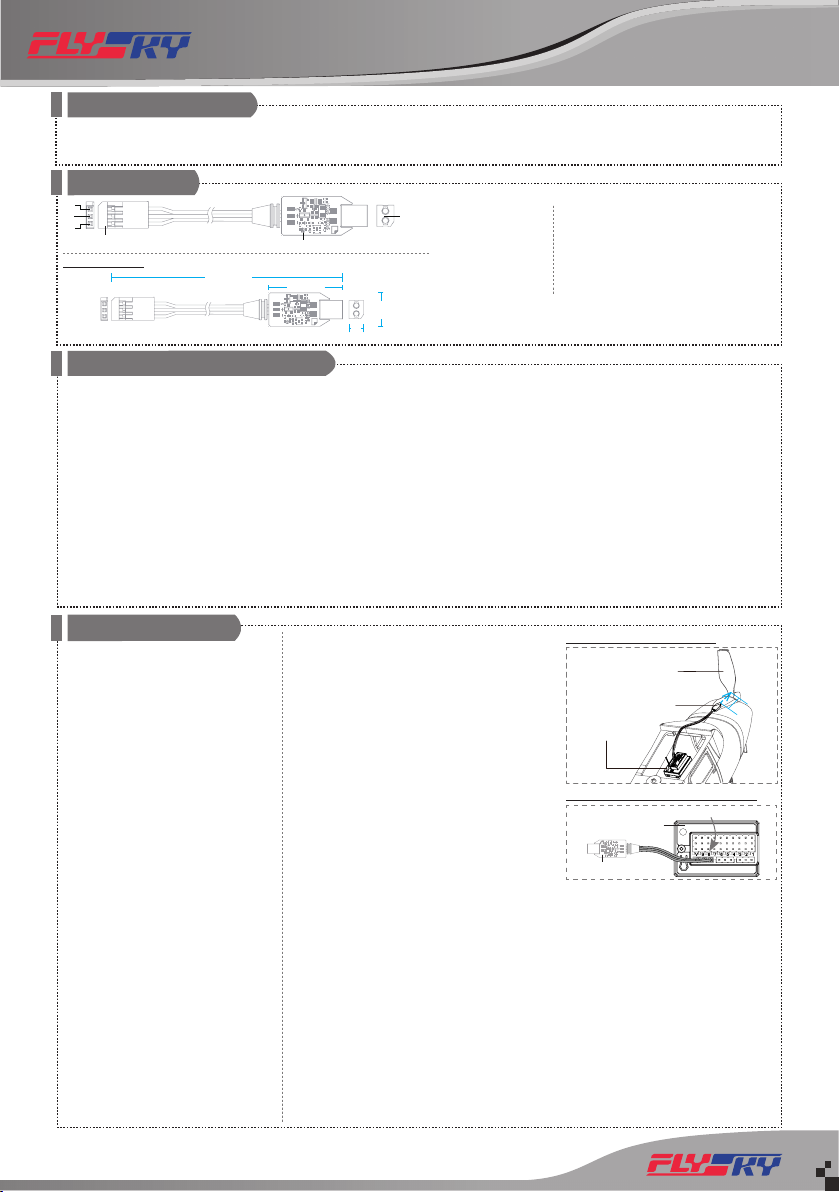
安装说明 Installation
光感转速传感器安装说明
安装步骤如下:
1. 使用 3M 贴将本传感器固定在模型合适
位置处 ( 如图),使光感探头与马达转
子反光面垂直,注意固定的面需平整。
也可使用扎带将其捆绑在模型上,注意
力度,避免扎带勒坏产品;
2. 如图所示,将舵机接口连接至接收机
Newport 接口,在与此接收机对码的发
射机端,将接收机对应的 Newport 接口
协议设置为 i-BUS2,即可在发射机端查
看相关信息。
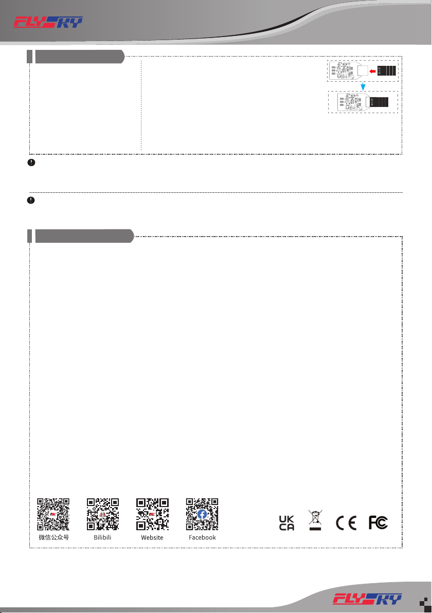
遮光罩使用说明
若在室外强光下使用本传感器,强烈的光线
会导致本传感器测量出现误差,在此情况下,
舵机接口 /Interface
注:
1. 将本传感器安装在靠近桨叶或马达转子
的位置,且光感探头与与桨叶或转子间距
离不超过 50mm 或 30mm(带遮光罩);
2. 不同应用对线材长度要求不同,如需加延
长线,请注意 FS-iBS01 接口为舵机接口,
针脚定义参考前面【概览】描述。
3. 适配支持 i-BUS2 协议的发射机:Noble
(固件版本V2.0.93及以上)、Noble Lite(固
件版本 V1.0.10 及以上)、Noble pro、
PL18(固件版本 1.0.55 及以上)和 PL18
Lite(固件版本 1.0.65 及以上);
4. 光感转速传感器正常工作时,LED灯常亮;
5. 若光感转速传感器已连接电源但未检测到
i-BUS2 信号,此时 LED 灯慢闪。
Mounting Instruction
Follow the steps below to install:
1. Use 3M stickers to x the optical perception sensor
at the appropriate location of the model as shown
in the gure. And make the optical perception
detection elementper pendicular to the reective
surface of the motor rotor. It should be noted that
the xed surface should be at. You can also use
a cable tie to tie it to the model. In this case, you
should control the force.
2. Connect the servo interface to the Newport
interface of the receiver as shown. Set the protocol
of the corresponding Newport interface of the
receiver to i-BUS2 at the transmitter side that has
bound with this receiver. As a result, you can view
the relevant information at the transmitter side.
Notes:
1. Install this sensor close to the blade or motor rotor. The distance between the optical perception
detection element and the propeller or rotor is not more than 50 mm or 30 mm (with a light
shield).
2. The cable length may vary to dierent applications. If you need to add an extension cable,
please note that the FS-iBS01 interface is a servo interface, and for the pin denition, refer to the
description in the previous Overview section.
3. The transmitters that support i-BUS2 protocol: Noble (rmware version V2.0.93 or later), Noble
Lite (rmware version V1.0.10 or later), Noble pro, PL18 (rmware version 1.0.55 or later) and PL18
Lite (rmware version 1.0.65 or later).
4. If the optical perception sensor is working properly, the LED is solid on at this time.
5. If the optical perception sensor is connected to power supply but no i-BUS2 signal is detected, the
LED ashes slowly at this time.
[1]
[2]
[3]
[4]
[5]
155mm155mm 25mm25mm
12mm12mm
5mm5mm(厚度)(厚度)
尺寸 /Dimensions:
接收机 /Receiver
安装示意图 /Installation Diagram
接收机 /Receiver
传感器 /RPM Sensor
桨叶 /Propeller
与接收机连接示意图 /Connection Diagram
Newport 接口 /Newport Interface
FS-iBS01
Instructions for Use of the Light Shield
If the sensor is used under strong outdoor light, the strong light will cause measurement errors of
50mm
FS-iBS01 RPM sensor
(Optical perception)
Http://www.ysky-cn.com
Copyright ©2022 Flysky Technology co., ltd.
认证相关 Certications
FCC Compliance Statement
This device complies with Part 15 of the FCC Rules. Operation is subject to the following two conditions: (1) this device may not cause harmful
interference, and (2) this device must accept any interference received, including interference that may cause undesired operation.
Warning: changes or modications not expressly approved by the party responsible for compliance could void the user's authority to operate the
equipment.
This equipment has been tested and found to comply with the limits for a Class B digital device, pursuant to Part 15 of the FCC Rules. These limits are
designed to provide reasonable protection against harmful interference in a residential installation. This equipment generates, uses and can radiate
radio frequency energy and, if not installed and used in accordance with the instructions, may cause harmful interference to radio communications.
However, there is no guarantee that interference will not occur in a particular installation.
If this equipment does cause harmful interference to radio or television reception, which can be determined by turning the equipment o and on, the
user is encouraged to try to correct the interference by one or more of the following measures:
-- Reorient or relocate the receiving antenna.
-- Increase the separation between the equipment and receiver.
-- Connect the equipment into an outlet on a circuit dierent from that to which the receiver is connected.
-- Consult the dealer or an experienced radio/TV technician for help.
EU DoC Declaration
Hereby, [Flysky Technology co., ltd] declares that the Radio Equipment [FS-iBS01] is in compliance with RED 2014/53/EU.
The full text of the EU DoC is available at the following internet www.yskytech.com/info_detail/10.html.
Environmentally Friendly Disposal
Old electrical appliances must not be disposed of together with the residual waste, but have to be disposed of separately. The disposal at the communal
collecting point via private persons is for free. The owner of old appliances is responsible to bring the appliances to these collecting points or to similar
collection points. With this little personal eort, you contribute to recycle valuable raw materials and the treatment of toxic substances.
UKCA Compliance Statement
Satises all the technical regulations applicable to the product within the scope of UK Radio Equipment Regulations (SI 2017/1206); UK Electrical
Equipment (Safety) Regulations (SI 2016/1101); and UK Electromagnetic Compatibility Regulations (SI 2016/1091).
本说明书中的图片和插图仅供参考,可能与实际产品外观有所不同。 产品设计和规格可能会有所更改,恕不另行通知。
Figures and illustrations in this manual are provided for reference only and may dier from actual product appearance. Product design and specicatiions may be changed without notice.
Manufacturer: Shenzhen FLYSKY Technology Co., Ltd.
Address: 16F, Huafeng Building, No. 6006 Shennan Road, Futian District, Shenzhen, Guangdong, China
Attentions:
• Ensure that the sensor is connected properly to the receiver, failure to do so may result in damage to the sensor.
• Ensure that the sensor is connected properly to i-BUS2 interface of the receiver before use.
• Do not touch a sensor during engine motor rotation.
注意事项:
• 为防止损坏光感转速传感器,请确保与接收机正确连接。
• 使用光感转速传感器前,请确保与接收机的 i-BUS2 接口相连。
• 请勿在电机旋转时触摸传感器。
需使用遮光罩。步骤如下:
1. 确认遮光罩的合适长度,沿剪裁提示
线剪掉多余部分;
2. 如图所示,将遮光罩包住光感探头。
安装说明 Installation
注:
1. 遮光罩上有三条剪裁提示线,方便您
裁剪不同的长度,以适配不同的应用 ;
2. 遮光罩长度越长效果越好,但同时
需注意与被测物体间距离不能超过
30mm。
the sensor. In this case, it is necessary to use the light shield. The
details are as follows:
1. Measure and conrm the appropriate length of the light
shield and cut o the excess along the cutting line.
2. Use the light shield to cover the optical perception detection
element as shown in the gure.
Notes:
1. There are three cutting lines on the light shield for your choice to get appropriate length for
dierent applications.
2. The longer the length of the light shield, the better the eect. However, the distance between the
light shield and the object to be measured is not allowed to exceed 30mm.
Table of contents
Other Fly Sky Accessories manuals


