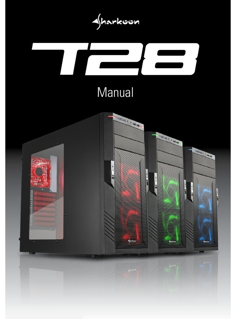
FlyTech 3000 Series User manual

USER’S MANUAL
BOOK PC 3000 SERIES
(B64 M.B.)
48200470

i
BOOK PC 3000 User’s Manual
This Manual was written for installation purposes. It is to provide the
information about the Book PC 3000 series with B64 all-in-one motherboard
for users.
1.Bookmarks
The words and phrases showing on the left side of this screen are the
bookmarks (subject of an operation) covering all topics in this manual.
2.Choosing a topic
Select and find any desired topic by using the scroll bar next to the
bookmarks. Click a bookmark to jump instantly to its topic that you wish to
read. (If you wish, you can also increase the size of the bookmark area by
dragging the dividing bar to the right.)
3.Magnifying the Page display
Select and use the Zoom tools to magnify or reduce the page display.
4.Finding a term
Click the Find button if you want to search for a particular term.
(However, using the bookmarks is usually quicker.)
Complete online documentation for Acrobat®Reader is located in the
Help directory for Acrobat®Reader.
Copyright of manufacture
November 2001, V1.0
Part No. 48200470

ii
COPYRIGHT
All rights reserved. The information contained in this guide has been
validated and reviewed for accuracy. No patent liability is assumed with
respect to the use of the information contained herein. While every
precaution has been taken in the preparation of this guide, the
Manufacturer assumes no responsibility for errors or omissions.
No part of this publication may be reproduced, stored in a retrieval
system, or transmitted in any form or by any means, electronic, mechanical,
photocopying, recording, or otherwise, without the prior written permission
of Manufacturer.
TRADEMARK
Intel®, Pentium®and MMX are registered trademarks of Intel®
Corporation. Microsoft®and Windows®are registered trademarks of
Microsoft Corporation. AWARD is a trademark of AWARD software INC.
General Notice: Other products and company names used herein are for
identification purposes only and may be trademarks of their respective
companies.
NOTICE
The contents of this manual are subject to change without notice.

iii
FEDERAL COMMUNICATIONS COMMISSION NOTICE
This equipment has been tested and found to comply with the limits fora
Class A computing device, pursuant to Subpart B of Part 15 of FCC Rules.
Only peripherals (computer input/output devices, monitors, printers, etc.)
certified to comply with the Class A limits may be attached to this computer.
Operation with non-certified peripherals is likely to result in interference to
radio and TV reception.
NOTICE: This equipment generates and uses radio frequency energy
and if not installed and used properly, that is, in strict accordance with this
user's manual, may cause interference to radio and television reception. It
has been type tested and found to comply with the limits for a Class A
computing device, pursuant to Part 15 of FCC Rules, which are designed to
provide reasonable protection against such interference in a residential
installation. However there is no guarantee that interference will not occur
in a particular installation. If this equipment does cause interference to radio
or television reception, which can be determined by turning the equipment
on and off, the user is encouraged to try to correct the interference by one
or more of the following measures:
•Reorient the receiving antenna
•Relocate the computer with respect to the receiver
•Move the computer away from the receiver
•Plug the computer into a different outlet so that computer and
receiver are on different branch circuits.
If necessary, the user should consult the supplier or an experienced
radio/television technician for additional suggestions.
The user may find the following booklet prepared by the Federal
Communications Commission helpful :
"How to identify and Resolve Radio-TV Interference Problems". This
book is available from the US Government Printing Office, Washington, D.C.
20402
CE
F
WARNING:
This is a Class A product. In a domestic environment this product may
cause radio interference in which case the user may be required to take
adequate measures.

iv
BATTERY REPLACEMENT
FWARNING:
Your computer is provided with a battery-powered Real-Time Clock
circuit. There is a danger of explosion and risk of personal injury if the
battery is incorrectly replaced or mistreated. Do not attempt to disassemble
the battery, immerse it in water or dispose of it in fire.

Contents
CHAPTER 1. PRECAUTION . . . . . . . . . . . . . . . . . . . . . . . . . . . . . . . . . .1-1
1.1 CHECK THE LINE VOLTAGE . . . . . . . . . . . . . . . . . . . . . . . . . . 1-1
1.2. ENVIRONMENTAL CONDITIONS . . . . . . . . . . . . . . . . . . . . . . 1-1
1.3. HANDLE THE SYSTEM CAREFULLY . . . . . . . . . . . . . . . .. . . 1-2
CHAPTER 2. GETTING STARTED . . . . . . . . . . . . . . . . . . . . . . . . . . . . .2-1
2.1. UNPACKING THE PACKAGE . . . . . . . . . . . . . . . . . . . . . . . . . .2-1
2.2. INTRODUCTION . . . . . . . . . . . . . . . . . . . . . . . . . . . . . . . . . . . .2-2
2.3. BOOK PC 3000 SERIES OUTLOOKING. . . . . . . . . . . . . . . . . .2-3
2.3.1. The Front View . . . . . . . . . . . . . . . . . . . . . . . . . . . . . . . . 2-3
2.3.2. The Back View . . . . . . . . . . . . . . . . . . . . . . . . . . . . . . . . .2-5
2.4. SETUP BOOK PC 3000 SERIES. . . . . . . . . . . . . . . . . . . . . . . .2-7
2.4.1. Removing the System Case . . . . . . . . . . . . . . . . . . . . . . 2-8
2.4.2. Setting Jumpers and DIP Switches. . . . . . . . . . . . . . . . . 2-9
2.4.3. Installing a CPU. . . . . . . . . . . . . . . . . . . . . . . . . . . . . .. 2-14
2.4.4. Installing a DIMM . . . . . . . . . . . . . . . . . . . . . . . . . . . . . .2-16
2.4.5. Installing HDD/FDD/CD-ROM Drive . . . . . . . . . . . . . . . 2-17
2.4.6. Installing an ISA/PCI Board . . . . . . . . . . . . . . . . . . . . . .2-19
2.4.7. Installing Other Peripherals. . . . . . . . . . . . . . . . . . . . . .2-22
2.5. SYSTEM ASSEMBLIES. . . . . . . . . . . . . . . . . . . . . . . . . . . . . .2-26
CHAPTER 3. TECHNICAL SPECIFICATION. . . . . . . . . . . . . . . . . . . . . 3-1
3.1. SPECIFICATION. . . . . . . . . . . . . . . . . . . . . . . . . . . . . . . . . . . . 3-1
3.2. CONNECTOR PIN ASSIGNMENTS. . . . . . . . . . . . . . . . . . . . . 3-2
CHAPTER 4. SYSTEM UTILITY SETUP. . . . . . . . . . . . . . . . . . . . . . . . . 4-1
4.1. SYSTEM UTILITY. . . . . . . . . . . . . . . . . . . . . . . . . . . . . . . . . . . .4-1
4.2. BIOS SETUP –VIA VT82C693 CHIPSET. . . . . . . . . . . . . . . . . 4-2
4.2.1. Starting the BIOS Setup. . . . . . . . . . . . . . . . . . . . . . . . . .4-2
4.2.2. Control Keys . . . . . . . . . . . . . . . . . . . . . . . . . . . . . . . . . . 4-3

4.2.3. Main Menu . . . . . . . . . . . . . . . . . . . . . . . . . . . . . . . . . . . .4-4
4.2.4. Standard CMOS Setup. . . . . . . . . . . . . . . . . . . . . . . . . . .4-6
4.2.5. BIOS Features Setup . . . . . . . . . . . . . . . . . . . . . . . . . . 4-10
4.2.6. Chipset Feature Setup . . . . . . . . . . . . . . . . . . . . . . . . . 4-17
4.2.7. Power Management Setup. . . . . . . . . . . . . . . . . . . . . . 4-22
4.2.8. PnP/PCI Configuration. . . . . . . . . . . . . . . . . . . . . . . . . .4-27
4.2.9. Integrated Peripherals. . . . . . . . . . . . . . . . . . . . . . . . . . 4-30
4.2.10 Password Setting . . . . . . . . . . . . . . . . . . . . . . . . . . . . .4-32
4.3. BIOS SETUP –VIA VT82C693 CHIPSET. . . . . . . . . . . .. . . . 4-34
4.3.1. Starting the BIOS Setup. . . . . . . . . . . . . . . . . . . . . . . . .4-34
4.3.2. Control Keys . . . . . . . . . . . . . . . . . . . . . . . . . . . . . . . . . 4-34
4.3.3. Main Menu . . . . . . . . . . . . . . . . . . . . . . . . . . . . . . . . . . .4-36
4.3.4. Standard CMOS Setup. . . . . . . . . . . . . . . . . . . . . . . . . .4-38
4.3.5. BIOS Features Setup . . . . . . . . . . . . . . . . . . . . . . . . . . 4-42
4.3.6. Chipset Feature Setup . . . . . . . . . . . . . . . . . . . . . . . . . 4-49
4.3.7. Power Management Setup. . . . . . . . . . . . . . . . . . . . . . 4-54
4.3.8. PnP/PCI Configuration. . . . . . . . . . . . . . . . . . . . . . . . . .4-59
4.3.9. Integrated Peripherals . . . . . . . . . . . . . . . . . . . . . . . . . .4-62
4.3.10 Password Setting . . . . . . . . . . . . . . . . . . . . . . . . . . . . .4-65
Appendix A. Fast Ethernet PCI Bus Controller. . . . . . . . . . . . . . . . . . . . I
1. The Feature of Intel 82559 ER Fast Ethernet PCI Controller. . . . . . I
2. The Feature of Intel 82559 Fast Ethernet PCI Controller. . . . . . . . . I
3. The Feature of Reltek8139C Fast Ethernet PCI Controller. . . . . . . .I

1-1
Chapter 1. Precaution
This section is written to protect both user and the system. In order to
lengthen the service life of the system, please read this section carefully.
1.1 Check the Line Voltage
The operating voltage for the 3000 series (B64) use an internal micro
ATX power supply FT-8015 should cover the range of 115V / 230V AC,
otherwise the system may be damaged.
Rating Line Voltage Frequency
115 / 230V AC 90~132 / 180 ~ 264V AC 47/63 Hz
êCaution:
The power supply use a voltage selector switch to select AC input
voltage of 115V or 230V. The switch will be set to the customer
required voltage position before being shipped.
1.2 Environmental Conditions
Place your 3000 series on a solid, level surface. Be sure to allow enough
space on each side so that you can have an easy access.
Avoid installing this system in an extremely hot or cold environment.
Avoid putting this system in a place exposed to direct sunlight, in a
closed car in the summer time, or near a heating device such as a stove.
Temperature: Operating Temperature: 5 °C ~ 35 °C.
Storage Temperature: -10 °C ~ 60 °C.
Do not use the system that has been left outdoors on a cold winter day.
The operating lowest ambient temperature is 5 °C.
Avoid moving the system rapidly from a hot place to a cold place or vice
versa. Otherwise, condensation may be caused form inside the system.

1-2
Keep the system away from damp air, water and dust. The operating
ambient humidity is 20 ~ 80% (non -condensing). The Non -operating
Relative Humidity is 20% ~ 80% (non-condensing). Avoid putting a
water-filled container such as a vase on or near the system.
Do not put the system in a place of strong vibration which may cause
serious damage to the hard disk inside the system( if a hard disk is
installed inside).
Do not place the system too close to a radio, television, or other
communication systems to avoid interference.
1.3. Handle the System Carefully
Do not put heavy objects on the system except a small light monitor.
Do not turn the system upside down. Otherwise, the disk drive may not
work properly.
When transport the system outdoors, it is always advisable to protect it
from damage by inserting a protective diskette into the disk drive.
When the system is not in use, remember to cover the system and store
it with care.
When the system is not in use, remember to cover the system and store
it with care.
When Operation is faulty, double check the operation procedure, if the
problem persists, contact your supplier.

2-1
Chapter 2. Getting Started
This chapter explains how to set up your new Book PC. It helps you
unpack the computer, identify all the parts, and put it all together.
2.1. Unpacking the package
Upon unpacking the 3000 series (B64) system, make sure that you have
the following items in good condition:
hAccessory Bag h3000 Series System Unit
hAC Power Cord hCD Driver Bank
If any of the above items are damaged or missing, please contact your
supplier immediately.
After you have removed all items, put the packing material and plastic
wraps into the packing box and move it to a storage area. Save them for
use when moving or shipping the computer.
JUMER
SETTING

2-2
2.2. Introduction
The main board used in the 3000 series Book PC is an B64 all-in-one
motherboard which contains CPU, RAM, ROM BIOS, floppy disk drive
controller, IDE hard disk controller, VGA chip, etc. The Dimension for
Book PC 3000 series is 300 (W) x320 (L) x90(H)mm.
hOutside the System Unit
The system unit is the main body of a PC system. Its equipment and
structures define almost all of the features & functions of the PC system.
It is a box-like structure with a metal casing enclosing all its electronic
components.
The outside of the system unit has LED indicating lights and input /output
connectors on it. The casing is made of metal so as to help with heat
dissipation to assure the proper function of the inside components.

2-3
2.3. Book PC 3000 Series Outlooking
2.3.1. The Front View
1. IR Port (option)
This infrared port complies with IrDA 1.0, IrDA 1.1 (SIR), and ASK
Standards which allow you to use wirelessly communication peripherals
such as a keyboard or mouse that comply with the standards Floppy
Disk Drive
2. Power indicator
When this green LED is lit, it indicates that system power is on.
When the LED is blinking, it indicates in suspend mode.
3.Hard Disk Drive Access LED
This glows when the computer is accessing the hard disk

2-4
4.LAN LED indicator
When lit this green LED indicates that the system is currently online or
connected to the Network.
5.Reset button
Press this button to reset your computer
6.Power /Suspend button
•When the computer is in soft-off mode, pressing this button turns on the
computer power.
•When the computer power is fully on, pressing this button briskly (less
than 4 seconds) puts the system into Suspend mode and pressing it
briskly again ends Suspend mode.
•When the computer power is on, pressing this button for more than 4
seconds turns the computer power OFF (soft-off).
7.Slim CD-ROM Drive
This is the CD-ROM drive of your computer, often configured as
drive D. The indicator on the drive glows when the system is accessing
the CD-ROM drive.
8.Floppy disk drive
This is the 3.5-inch floppy disk drive (FDD) of your computer, refereed
to as driver A. The indicator on the FDD glows when the system is
accessing the floppy disk drive.

2-5
2.3.2. The Back View
1. Power Connector
This is for connection the AC power cord
2. AC Input Selection
This is switch for selection 115 / 230V AC voltage.
3.USB Port
The Universal Serial Bus Port is for connecting the USB devices.
4. Microphone Connector
This can be connected to an external microphone
5. Line-In Connector (Audio Input Connector )
This can be connected to the line-out connector of any Hi-Fi set, radio set,
CD player, synthesizer, walkman, etc.
6. Line-Out Connector (Audio Output Connector )
This can be connected to a set of headphones, external speakers with
amplifier or an audio recording device.

2-6
7.PS2 Keyboard Port
This 6-pin mini-Din port is for connecting a PS2 keyboard.
8. PS2 Mouse Port
This 6-pin mini-Din port is for connecting a PS2 mouse.
9. VGA Port
This 15-pin analog port is for connecting a display monitor
10. Parallel Port
This 25-pin port is for connecting a parallel port device such as parallel
printer.
11.Serial Port (COM2)
This 9-pin port is for connecting a serial device.
12. Serial Port (COM1)
This 9-pin port is for connecting a serial device.
13. RJ-45 LAN Connector (option)
This is for plugging the LAN cable into the connector.
14. Expansion slots
Behind this cover are three (3) expansion slots for installing expansion
cards.
15.TV Composite Port (option)
This port is for connecting to the AV terminal of TV
16. System Cooling Fan (option)
This is a 50mm x 50mm x 15 (height)mm DC fan built-in system.
17.Modem Port (option)
This is a RJ11 phone jack for connecting a internal modem.

2-7
2.4 Setup Book PC 3000 Series
Setup the Book PC 3000 Series according to the following steps as listed
below. If you don't use the specified options, skip that step.
Step
2.4.1 Removing a Case
2.4.2 Setting the Jumpers and DIP Switches
2.4.3 Installing a CPU
2.4.4 Installing DIMMs
2.4.5 Installing a HDD/FDD/CD-ROM Drive
2.4.6 Installing a ISA/PCI Board
2.4.7 Installing Other Peripherals
2.4.7.1. Installing a Game Cable
2.4.7.2. Installing a Modem Daughter Card
2.4.7.3. Installing a TV Function
êCaution :
Whenever you connect or disconnect any component, be sure that your
computer turned off and that your computer is disconnected from its
power sources. Plugging or unplugging any item when the computer is
receiving power can cause power surges and damage your computer.

2-8
2.4.1 Removing the System Case
Before installing any component, you would have to remove the case of
the system unit. The procedures are illustrated below:
1.Use a screw driver to remove the two screws on both sides of the
system unit and three screws on the rear panel side of the system unit.
2. Slide off the system casing. ( See below figure )
When finish disassembly, reverse the steps. to secure the support
chassis to main system and slid back the system case.

2-9
2.4.2 Setting Jumpers and DIP Switches
There are jumpers and DIP switches on the board of Book PC 3000.
You can set them to control how the system operates.
For three-pin jumpers, the jumper setting is 1-2 when the jumper
connects pins 1 and 2. The setting is 2-3 when pins 2 and 3 are
connected. You see a 1 and a 3 printed on the circuit board to identify
these pins. Also, one of the lines surrounding jumpers is thick, which
indicates pin NO.1.
To move a jumper from one position to another, use needle-nose pliers or
tweezers to pull it off the pins and move it to the desired position.
êCaution
Be careful not to bend the jumper pins or damage any components on
the board.
Do not change settings for jumpers and DIP switches not covered in this
manual.

2-10
nJumpers and DIP Switches Locations
The figure below shows the location of jumpers and the DIP switches on
the Book PC 3000 main board -B64 version 1.x.
* Jumper and Connector (Black area indicates pin 1).
BAT1
168-PIN DIMM RAM SOCKET-DIMM 1
168-PIN DIMM RAM SOCKET-DIMM 2
BIOS
U15
5
12
6
RAGE1284XL
CN1 CN2 CN3 CN4 CN7 CN8
CN10
JP3
CN5
JP6
U19
CN28 CN29
PCI SLOT1
PCI SLOT2
CPU
U33
CN24
CN6 CN15
JP7
CN21
CN27
7
8
1
2
CN23
JP9
1
2
11
12 CN25
CN26
PGA370
JP8
1
12 11
82443BX-A
U30
JP412
CN14
2
1CN19
2
1
CN20 1
2
CN22
CN18
2
U18
CN13
CN11
JP1 JP2
CN17CN16
JP5
34
1
2
5
6
1
2
5
6
CN30
12
1516
14
1 8
1
1
1
1
1 1
11
1
12
1 1
1
1
VIA
INTEL
VT82C596B
FW82371EB

2-11
nTable for Jumper Location Description:
Use the information in the following table to change the jumpers and the
DIP switches.
Jumpers Functions
JP3, JP4 M-System DiskOnChip
JP5,JP6 AT/ATX Power Mode
JP7 CMOS Operation Mode
JP8, CPU Frequency Selection
U20,U23,U26,U28 8MB VGA RAM Configuration
U16,U22,,U25,U27 32MB VGA RAM Configuration
DIMM1,DIMM2 System RAM Configuration
JP1,JP2 COM port pin1, power selection
h.M-System DiskOnChip: JP3, JP4
Address JP 3 JP 4
0C800-0C9FF 1-21-2
0CC00 -0CDFF 1-23-4
0D000 -0D1FF 3-41-2
0D400 -0D5FF 3-43-4
0D800 -0D9FF 5-61-2
0DC00 -0DDFF (Default) 5-63-4
h.ATX / AT Power Mode: JP5, JP6
Function JP5 JP6
FT-
8065 AT Internal power supply
1-2Close
ATX power supply (default) 2-3Open
h.CMOS Operation Mode: JP7
Function JP7
CMOS Normal (Default) 2-3
CMOS Reset 1-2
This manual suits for next models
1
Table of contents

