FMA Direct Super 30 User manual
4
FMA limited warranty for electronic speed controls
FMA, Inc. warrants this product to be free of manufacturing defects for the term of 90 days from the date of pur-
chase. Should any defects covered by this warranty occur, the product shall be repaired or replaced with a unit of
equal performance by FMA or an authorized FMA service station.
Limits and exclusions
This warranty may be enforced only by the original purchaser, who uses this product in its original condition as
purchased, in strict accordance with the product’s instructions. Units returned for warranty service to an FMA
service center will be accepted for service when shipped postpaid, with a copy of the original sales receipt or
warranty registration form, to the service station designated by FMA.
This warranty does not apply to:
Consequential or incidental losses resulting from the use of this product.
Damage resulting from accident, misuse, abuse, neglect, electrical surges, reversed polarity on connectors,
lightning or other acts of God.
Damage from failure to follow instructions supplied with the product.
Damage occurring during shipment of the product either to the customer or from the customer for service
(claims must be presented to the carrier).
Damage resulting from repair, adjustment, or any alteration of the product by anyone other than an authorized
FMA technician.
Installation or removal charges, or damage caused by improper installation or removal.
Call (301) 668-7614 for more information about service and warranty repairs.
Super 30 ESC specifications
Model ASC30
Functions Proportional throttle, throttle end point adjustment (EPA), brake,
battery eliminator circuit (BEC), low voltage cutoff (LVC), restart
Input 2 to 4 Lithium Polymer cells in series, or 5 to 12 NiCd/NiMH cells
in series (LVC enabled), 3 to 12 NiCd/NiMH cells (LVC disabled)
Input operating voltage 2.1 to 18 VDC
Motor support 1 DC motor, up to 30A current draw (does not support brushless
motors)
Frequency 1.5 kHz
Continuous output current 30 A
Peak output current 400 A (FET rating)
Internal resistance 2.75 milliohm
BEC output 5.0
±
0.5 VDC at 1A maximum
Dimensions 1.35" x 0.75" x 0.40" (34.3mm x 19mm x 10.2mm)
Super 30 ESC cell detect and low voltage cutoff specifications
For initial voltage Pack type/size* is assumed to be And cutoff voltage (when enabled) is
5.30 to 7.15 V NiCd/NiMH, 5 cells 5.2 ±0.1 V
7.16 to 8.55 V NiCd/NiMH, 6 cells; or LiPo, 2 cells 5.3 ±0.1 V
8.56 to 9.95 V NiCd/NiMH, 7 cells 5.4 ±0.1 V
9.96 to 11.20 V NiCd/NiMH, 8 cells 6.1 ±0.1 V
11.21 to 12.45 V NiCd/NiMH, 9 cells; or LiPo, 3 cells 8.4 ±0.1 V
16.06 up NiCd/NiMH, 12 cells; or LiPo, 4 cells 11.0 ±0.1 V
12.46 to 14.50 V NiCd/NiMH, 10 cells 9.3 ±0.1 V
14.51 to 16.05 V NiCd/NiMH, 11 cells 10.3 ±0.1 V
*number of cells connected in series
FMA, Inc.
5716A Industry Lane
Frederick, MD 21704
Sales: (800) 343-2934
Technical: (301) 668-7614
www.fmadirect.com
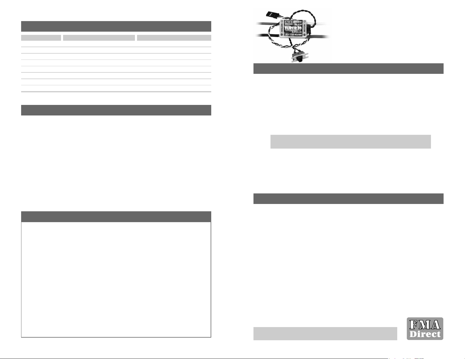
Super 30 Auto Cell Detect
Electronic Speed Control
Model ASC30 for electric-powered aircraft using
Lithium Polymer, NiCd or NiMH battery packs
Features
Works with NiCd, NiMH and Lithium Polymer (LiPo) packs.
User switchable brake.
User switchable Low Voltage Cutoff. When enabled, cutoff voltage is automatically set based
on initial battery pack voltage.
Throttle End Point Adjustment (EPA).
Battery Eliminator Circuit (BEC) powers receiver from motor battery.
Heavy-duty diode reduces electrical noise.
Kokam/USA Lithium Polymer cells are the next-generation replacement for NiCd, NiMH and
Lithium Ion cells. This unique power technology offers high energy density, low weight, long
life, safe operation and environmentally-friendly chemistry. Order Kokam/USA cells and packs
through the Kokam/USA Web site, www.kokamusa.com (or www.fmadirect.com). LiPo technical
and application information is available in the Support section of the Web site.
Precautions
Follow all instructions in this manual to assure safe operation.
Observe frequency control. If someone else is operating a radio controlled model on the same
channel as your transmitter,
do not turn on your transmitter—even for a short time.
Your
transmitter has a channel number marked somewhere on its case. When a model receives
signals from two transmitters on the same channel at the same time, it cannot be controlled and
will crash—possibly causing personal injury or property damage.
For safety, most RC flying
fields have formal frequency control rules. Follow them carefully.
Do not operate your radio control transmitter within 3 miles of a flying field. Even at a
distance, your transmitter can cause interference.
Make sure your LiPo packs are above 3.7V/cell when you first connect them to the ESC and
apply power. The ESC sets its Low Voltage Cutoff by measuring initial pack voltage. If the
LiPo pack voltage is too low, the Low Voltage Cutoff may be set too low, and cells could be
over-discharged. Charge state is less critical for NiCd/NiMH packs, but it’s always a good idea
to start with a freshly charged pack.
The Super 30 ESC works with packs of 5 to 12 NiCd/NiMH or 2 to 4 LiPo cells in series. If
the Low Voltage Cutoff is disabled, the ESC supports packs with 3 to 4 NiCd/NiMH cells in
series (however, your receiver/servos may stop operating at the lower voltage near the end of a
run).
Never disable the Low Voltage Cutoff when using the ESC with LiPo packs.
Note:
When using LiPo batteries in fuel-powered models, use an FMA voltage
regulator/LED indicator, such as the Sport VRLI.
2
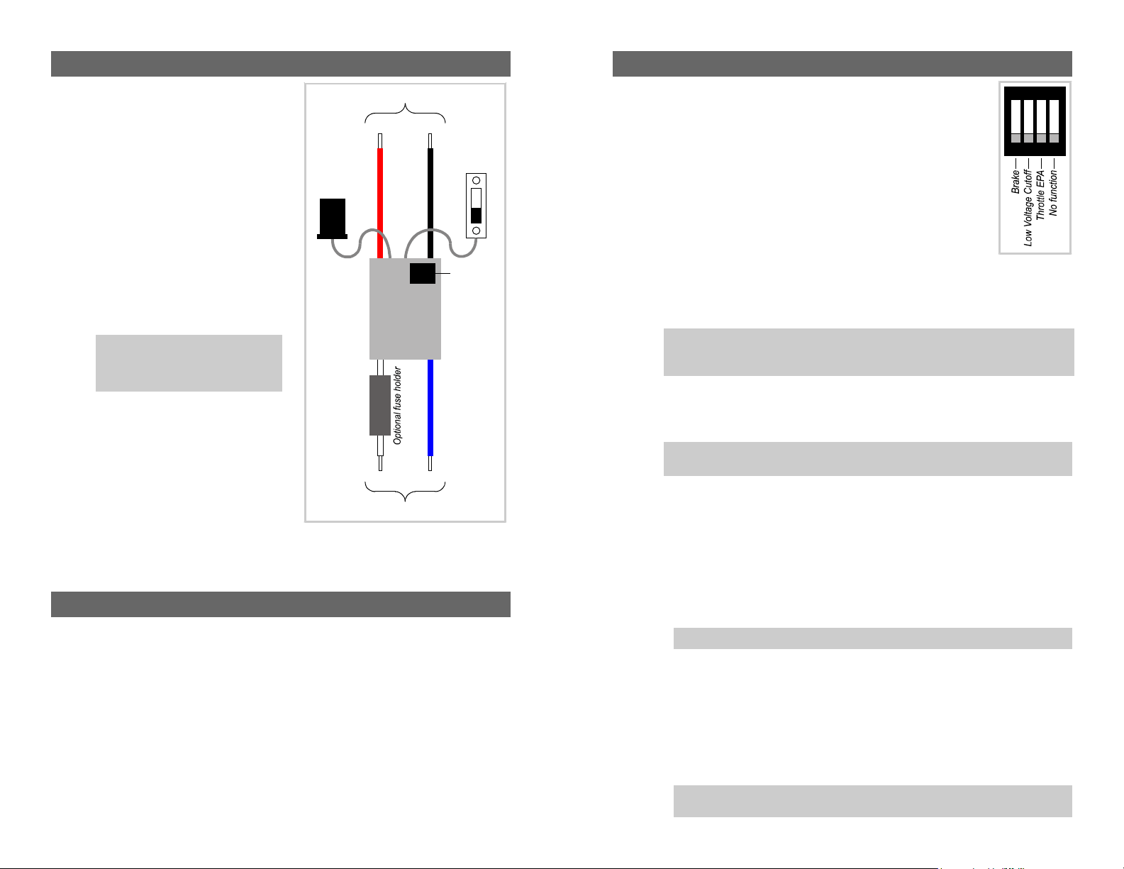
Installing the ESC
You must supply:
Battery connector rated for expected current flow
(up to 30A) from battery pack. Recommended:
Deans Ultra or Sermos connector.
Do not use a
servo connector, as it cannot handle the high
current.
Optional: 30A fuse and inline fuse holder.
1. Optional: Cut red and black battery wires, and/or
blue and white motor wires, to a length
appropriate for your installation.
2. Optional: Cut white ( + ) wire and solder in fuse
holder. Insert fuse into fuse holder.
3. Solder red ( + ) wire to battery connector positive
terminal.
4. Solder black ( – ) wire to battery connector
negative terminal.
5. Solder blue wire to motor’s negative ( – )
terminal.
6. Solder white wire to motor’s positive ( + )
terminal.
7. Attach servo connector to throttle channel on
receiver (observe polarity!).
8. Set on/off switch to
off
position.
9. Attach battery connector to battery pack.
Solder to battery connector (not supplied)
Black wireRed wire
+–
Blue wireWhite wire
+–
Solder to motor terminals
Attach to
receiver
throttle
channel
On/off switch
Switches
(see text)
Note:
Double-check battery connector
polarity. Damage caused by reversing
battery polarity is not covered by the
warranty!
Tips for using the ESC
If you store throttle corrections as described in step 3 on the next page, then you don’t have to
repeat the procedure before each flight. The ESC is ready to go (using stored EPA settings)
when you turn it on, and the motor will turn as soon as you move the throttle stick away from
the off position.
If you fast-charge your battery pack, wait at least 5 minutes before using it to power the ESC.
This assures the ESC can properly determine the number of cells in the pack.
After you connect your charged battery pack to the ESC and turn power on, wait about 3 sec-
onds before advancing the throttle. This gives the ESC time to accurately determine the num-
ber of cells in the battery pack.
If the motor cuts off in flight:
1. Move throttle stick to off.
2. Move throttle stick back up.
If the battery pack is in good condition, the ESC should provide 2 restarts.
3
Setting up the ESC
1.
The Brake
stops motor rotation when the throttle is off and when the Low
Voltage Cutoff (see step 2, below) cuts power to the motor. Braking is often
used when the aircraft is equipped with a folding propeller.
To enable the brake:
set Switch 1 on.
or
To disable the brake:
set Switch 1 off.
2.
Low Voltage Cutoff
turns off the motor when battery voltage approaches the
minimum recommended voltage for the pack size detected by the ESC. This
enables the battery to maintain radio system functions for a short time—
enough time to glide the aircraft to landing. Low voltage cutoff also prevents
cell damage from deep discharge.
You must enable low voltage cutoff when
using LiPo batteries, which can be permanently damaged by low voltage conditions.
To enable low voltage cutoff:
set Switch 2 on (required for LiPo packs).
or
To disable low voltage cutoff:
set Switch 2 off.
3. Throttle
End Point Adjustment
(EPA) provides better tracking between throttle stick position
and actual motor speed. With EPA correctly set, the motor is off when the throttle stick is all
the way down, and reaches maximum speed when the throttle is all the way up.
To set up EPA:
a. With the ESC off, set Switch 3 on.
b. Move your transmitter’s throttle stick all the way
down.
c. Turn on your transmitter, then turn on the ESC/receiver. The motor will not rotate until
step d is complete.
d. Wait 3 seconds for the ESC to determine the number of cells in the pack.
e. Move the throttle stick all the way
up
(or to the desired position for maximum motor speed)
and
hold it there for at least 3 seconds.
Then move the throttle stick all the way
down.
f. Test throttle operation: Hold the aircraft securely and clear of the propeller, then move the
throttle stick full up. The motor should turn at maximum RPM. Move the throttle stick all
the way down to turn off the motor.
g. Store EPA settings: Set Switch 3 off. The settings are now stored and will be available for
future flights.
ON
1234
Note:
The ESC can be used with packs of 3 or 4 NiCd/NiMH cells in series when the Low
Voltage Cutoff is disabled.
CAUTION:
If you disable LVC, the ESC cannot safeguard
against depleting the battery to the point where you won’t be able to control the aircraft.
Tip:
The ESC doesn’t care whether the throttle channel is reversed or not. EPA as-
sumes the initial throttle stick position (normally all the way down) is “motor off.”
CAUTION:
The motor is now active and will rotate if you move the throttle stick up.
Note:
If you forget to set switch 3 to off in step g above, you will have to repeat the
EPA setup each time you cycle power on the ESC.
This manual suits for next models
1
Other FMA Direct Motorized Toy Car manuals

Popular Motorized Toy Car manuals by other brands

REVELL
REVELL Ford Mustang GT 2005 Assembly manual

Carisma
Carisma GT14B instruction manual

HPI Racing
HPI Racing Hot Bodies D216 instruction manual

Vintage Air
Vintage Air 1970-72 Cutlass manual

Carrera RC
Carrera RC Nintendo Mario Kart - Mario Gold Assembly and operating instructions

FMS
FMS 1:24 FCX24 UNIMOG instruction manual

Team Losi
Team Losi Mini-Monster Baja Operation manual

Phoenix Model
Phoenix Model Domino instruction manual

REVELL
REVELL ‘70 Dodge Challenger T/A 2’n1 Assebly instructions

O'Donnell
O'Donnell Z01B Assembly instructions

REVELL
REVELL 1970 Chevelle SS 454 manual

Eduard
Eduard Krupp Protze 6x4 1/48 quick start guide


