FMA RAZOR User manual
1
RAZOR Flying Wing Almost Ready-To-Fly R/C Airplane
ASSEMBLY AND OPERATIONS MANUAL FOR PARK RAZOR, 400 AND 600 CLASS KITS AND
RTF MODELS - PARK RAZOR ASSEMBLY ALSO REQUIRES PARK RAZOR ADDENDUM - PARK
RAZOR DOES NOT CONTAIN CARBON FIBER SPAR
NOTE: PLEASE READ MANUAL COMPLETELY BEFORE OPERATION
FMA, Inc.
5716A Industry Lane
Frederick, MD 21704
Sales: (800) 343-2934 -Technical: (301) 668-7614
www.fmadirect.com
NEW, IMPROVED!
NOW CONTAINS CARBON
FIBER SPAR!
Manual Release V 2.0

2
Thank you for purchasing the FMA Direct RAZOR ARF series R/C aircraft. RAZOR is available in fourteen basic kit
or Almost-Ready-To-Fly configurations, ranging from a hand-toss glider for youngsters to a 600 Class
Performance Electric capable of speeds in excess of 60 MPH in level flight. RAZOR is designed using state-of-the-
art computer modeling to be extremely efficient, versatile, and rugged. Injection molded of ARCEL(TM), a
revolutionary new type of foam composed of expanded polystyrene and polyethylene, the basic airframe is
extremely strong, yet highly flexible. Extensive flight testing by FMA engineers has demonstrated the incredible
shock absorption and impact resistance of RAZOR by spinning the airplane in from as high as 100 feet directly on
the nose with little or no damage to the basic wing structure. With the addition of a 22” carbon fiber spar in-
cluded in the kits, RAZOR is arguably the most durable R/C aircraft available today. RAZOR is available in blue,
white, and gray and requires no painting, covering or finishing of any type. However, unlike other foams,
ARCELTM) can be painted or trimmed with a wide range of paints including Krylon™ from your hardware store.
Additionally, ARCEL(TM) is not damaged by application of CYA cements or glow fuels.
All basic RAZOR kits ship complete with airframe, elevons, winglets, ABS plastic tray and canopy, pushrods and
related hardware. Kits are configured to support slope soaring, park flier, 400 Class electric motors, or 600 Class
electric motors. The various ARF products ship with either 1) propulsion - which includes motor, ESC (electronic
speed control), propeller and propeller adapter, and 7 cell battery power pack, 2) flight pack - which includes
receiver battery (slope model), receiver, and servos, or 3) a combination of both propulsion and flight pack
equipment. The motorized versions include 1) a 280 Class, 6V electric motor, 2) a 400 Class, 6V electric motor, 3)
a 600 Class, 7.2V “endurance” motor, or 4) a 600 Class, 7.2V “performance” motor. The following table itemizes
the package contents and basic flight characteristics of the latter three electric, motorized ARF models. The
information presented in this table and any other specifications listed in this manual were current as of the date
the manual was written and are subject to change without notice. Furthermore, at the time this manual was
constructed, FMA was working on delivering additional models that include ARF electric models complete with
transmitter, receiver crystal and charger, as well as ultra-high-performance gas powered kits.
400 Class RTF Models 600 Class “Endurance” Models 600 Class “Performance” RTF Models
Propulsion Includes:
Motor 400 Class 6V Motor 600 Class, Low Current 7.2V Motor 600 Class 7.2V Motor
Electronic Speed Control Mini 20 - 20 Amp Miniature ESC Mini 30 - 30 Amp Miniature ESC Mini 30 - 30 Amp Miniature ESC
Propeller Master Airscrew 5.5 x 4 Master Airscrew 8 x 4 Master Airscrew 8 x 4
Propeller Adapter PA400 PA600 PA600
Power Pack Battery Sanyo 7 Cell 600AE w/Tamiya Sanyo 7 Cell 800AR w/Tamiya Sanyo 7 Cell 800AR w/Deans Ultra
Max Current Consumption 10 Amps Static 17 Amps Static 28 Amps Static
Flight Pack Includes:
Receiver (FM or AM) 72 MHz Fortress Micro FM or AM Fortress Micro FM or AM Fortress Micro FM or AM
Servos (Qty 2) S80, S100 or PS30 S80, S100 or PS30 S80, S100 or PS30
Specifications:
Airframe Material ARCEL(TM) Foam ARCEL(TM) Foam ARCEL(TM) Foam
Manufacturing Technique Injection Molded Injection Molded Injection Molded
Wing Span 48 Inches 48 Inches 48 Inches
Wing Design Swept/Tapered Wing Swept/Tapered Wing Swept/Tapered Wing
Airfoil Semi-Symmetrical w/ Reflex Semi-Symmetrical w/ Reflex Semi-Symmetrical w/ Reflex
Approx. Weight w/ FMA Equip. 20 Oz. ± 1 Oz. 31 Oz. ± 1 Oz. 31 Oz. ± 1 Oz.
Approx. Wing Area 3.11 Sq. Feet 3.11 Sq. Feet 3.11 Sq. Feet
Nominal Wing Loading 6.43 Oz. / Sq. Foot 9.97 Oz. / Sq. Foot 9.97 Oz. / Sq. Foot
Approx. Flight Time/Top Speed 5 – 14 min. / 35 mph 5 – 11 min. / 45 mph 3.5 – 11 min. / 60 mph
Flight Characteristics Docile, Thermal, Aerobatic Moderate Speed, Aerobatic High Speed, Highly Aerobatic
Pilot Skill Requirements Beginner to Moderate Moderate to Advanced Advanced
Transmitter Requirements FM or AM, 3 Channel FM or AM, 3 Channel FM or AM, 3 Channel
Mixing Requirements Elevon Mix @ Tx or Rcv Elevon Mix @ Tx or Rcv Elevon Mix @ Tx or Rcv
Recommended Tx Capabilities Dual Rates or Expo Dual Rates or Expo Dual Rates or Expo
INTRODUCTION
SPECIFICATIONS
INDEX
♦ INTRODUCTION & SPECIFICATIONS ----------------------------------------------------------------------------------------------2
♦ SAFETY PRECAUTIONS & PACKAGE CONTENTS -------------------------------------------------------------------------3 - 4
♦ ASSEMBLY INSTRUCTIONS --------------------------------------------------------------------------------------------------- 4 - 18
♦ SETTING UP AND FLYING THE MODEL AND SPARE PARTS ------------------------------------------------------- 18 - 20

3
SAFETY PRECAUTIONS
THIS RADIO CONTROL MODEL IS NOT A TOY! PLEASE OBSERVE THE FOLLOWING CAREFULLY:
♦
FIRST-TIME BUILDERS SHOULD SEEK ADVICE FROM PEOPLE HAVING BUILDING EXPERIENCE IN
ORDER TO ASSEMBLE THE MODEL CORRECTLY AND ENSURE SUCCESSFUL OPERATION.
♦
ASSEMBLE THIS KIT ONLY IN PLACES OUTSIDE THE REACH OF CHILDREN.
♦
FOLLOW ALL ASSEMBLY AND SAFETY INSTRUCTIONS CONTAINED WITHIN THIS MANUAL TO
ENSURE SAFE OPERATION.
♦
NEVER FLY RADIO CONTROL MODELS IN CONGESTED AREAS OR CLOSE TO POWER LINES
♦
USE CAUTION WHEN STARTING THE MOTOR - KEEP HANDS CLEAR OF PROPELLER AT ALL
TIMES - ESPECIALLY DURING LAUNCH.
♦
FMA, INC. WILL NOT ACCEPT ANY LIABILITY RESULTING FROM FAILURE TO ASSEMBLE AND
OPERATE THIS MODEL AIRPLANE IN ACCORDANCE WITH THE RAZOR ASSEMBLY AND
OPERATIONS MANUAL.
♦
IN SOME AREAS OF THE COUNTRY IT IS NOT LEGAL TO FLY AT FIELDS OTHER THAN APPROVED
R/C FLYING FIELDS. CHECK WITH AUTHORITIES IN YOUR AREA, JOIN YOUR LOCAL CLUB.
♦
FMA, INC. RECOMMENDS MEMEBERSHIP IN AMA (ACADEMY OF MODEL AERONAUTICS) FOR
PURPOSES OF INSURANCE - PLEASE CONTACT LOCAL AMA CHARTER FOR DETAILS.
!
The product you have purchased is powered by a rechargeable battery. The battery is recyclable. At the
end of its useful life, under various national, state, and local laws, it may be illegal to dispose of this
battery into the municipal waste stream. Check with your local solid waste officials for details in your area
for recycling options or disposal.
PACKAGE CONTENTS
Carefully unpack the contents of your RAZOR kit and lay the parts out on a clean workspace, ready for assembly.
Identify your kit and verify that it contains the items listed in the following table. Note: if you discover that
something is missing or damaged, please contact the authorized FMA Direct dealer where you purchased the
product or phone FMA Direct at (301) 668-7614.
MODEL: CONTAINS: CONTAINS: CONTAINS:
RZRSLPKIT/RZR400KIT 1 LEFT, 1 RIGHT WING
1 ELEVON PACK 2 ELEVONS
1 WINGLET PACK 2 WINGLETS
1 400 PLASTICS PACK 1 400 TRAY, 1 CANOPY
1 HARDWARE PACK 1 PUSHROD PACK 1 LEFT, 1 RIGHT PUSHROD
1 CONTROL HORN PACK 2 CONTROL HORNS, 4 SCREWS
1 MTL CLEVIS PACK 2 CLEVIS, 2 RETAINING CLIPS
ELEVON TAPE 2 PCS. 0.005” LEXAN W/ ADHESIVE
STRUCTURAL TAPE 4 PCS. 0.010” LEXAN W/ ADHESIVE
SCREEN CLOTH 1 2” X 4” 120 GRIT
MOTOR TIE 1 8” X 0.142” NYLON TIE
HOOK & LOOP TAPE 1 5/8” X 2” MALE AND FEMALE
1 22” 5.5mm CARBON SHAFT
OWNER’S MANUAL
RZRSLPRTF1 RZRSLPKIT CONTENTS PLUS:
1 MICRO RCVR FM OR AM
2 S80, S100 OR PS30 SERVOS
1 MICRO SWITCH HARNESS
1 4 CELL 110 mAh BATTERY
RZR400RTF1 RZR400KIT CONTENTS PLUS:
1 400 MOTOR PACK (ASSY) 1 400 CLASS 6V MOTOR
2 0.01UF CAPACITORS
1 MINI 20 ESC
1 SHOTTKY DIODE
1 TAMIYA MALE CONNECTOR
1 PROPELLER (5.5 X 4)
1 400 PROP ADAPTER 1 ADAPTER SHAFT
1 SPINNER
2 HEX SET SCREWS
1 7 CELL 600AE POWER PACK
RZR400RTF2 RZR400RTF1 CONTENTS PLUS:
1 MICRO RCVR FM OR AM
2 S80, S100 OR PS30 SERVOS
4
MODEL: CONTAINS: CONTAINS: CONTAINS:
RZR600KIT 1 LEFT, 1 RIGHT WING
1 ELEVON PACK 2 ELEVONS
1 WINGLET PACK 2 WINGLETS
1 600 PLASTICS PACK 1 600 TRAY, 1 CANOPY
1 HARDWARE PACK 1 PUSHROD PACK 1 LEFT, 1 RIGHT PUSHROD
1 CONTROL HORN PACK 2 CONTROL HORNS, 4 SCREWS
1 MTL CLEVIS PACK 2 CLEVIS, 2 RETAINING CLIPS
ELEVON TAPE 2 PCS. 0.005” LEXAN W/ ADHESIVE
STRUCTURAL TAPE 6 PCS. 0.010” LEXAN W/ ADHESIVE
SCREEN CLOTH 1 2” X 4” 120 GRIT
MOTOR TIE 1 8” X 0.142” NYLON TIE
HOOK & LOOP TAPE 1 5/8” X 2” MALE AND FEMALE
1 22” 5.5mm CARBON SHAFT
OWNER’S MANUAL
RZR600RTF1/RZR600RTF3 RZR600KIT CONTENTS PLUS:
1 600 MOTOR PACK (ASSY) 1 600 CLASS 7.2V MOTOR “PERFORMANCE” OR “ENDURANCE”
2 0.01UF CAPACITORS
1 MINI 30 ESC
1 SHOTTKY DIODE
1 DEANS OR TAMIYA MALE “PERFORMANCE” OR “ENDURANCE”
1 PROPELLER (8 X 4)
1 600 PROP ADAPTER 1 ADAPTER SHAFT
1 SPINNER
2 HEX SET SCREWS
1 7 CELL 800AR POWER PACK
RZR600RTF2/RZR600RTF4 RZR600RTF1 OR 3 CONTENTS
PLUS:
1 MICRO RCVR FM OR AM
2 S80, S100 OR PS30 SERVOS
ASSEMBLY INSTRUCTIONS
Proceed carefully through each of the following assembly steps. Please read each step completely before you
begin that step. If you are uncertain about the instructions provided, please call FMA Direct technical assistance
at (301) 831-8980.
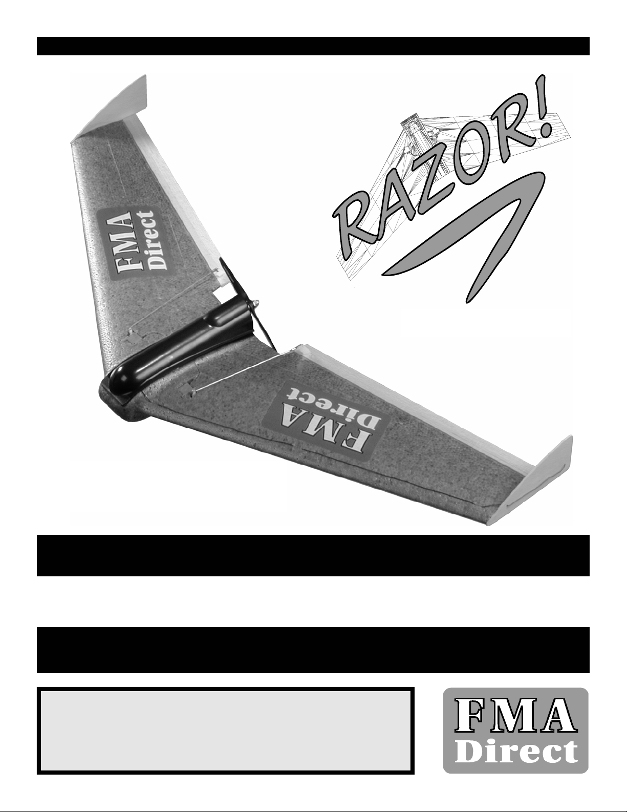
STEP 1: ARCEL(TM) foam contains polyethylene. While this particular
compound is the key to the strength of the foam, when parts are
injection molded using ARCEL(TM), the surface finish or “skin” that
forms does not readily accept bonding agents. For this reason, it is
important to prepare the surfaces of your model for bonding by lightly
sanding the skin on the wing panels where you will apply adhesives.
When sanding ARCEL(TM), use light, brisk, back-and-forth motions until
the finish is dull. Do not sand so deeply that you change the shape of
the joints - just remove the “shiny” look. Using the supplied 2” x 4”,
120 grit screen cloth, carefully sand the inside portions of both wing
halves where the wings will be joined.
STEP 2: Using the supplied 2” x 4”, 120 grit screen cloth, carefully
sand the tops of the fuselage halves where the equipment tray will
later be joined to the fuselage. The tray fits into the recessed area
marked by a ledge around the fuselage top. Sand inside of the ledge
so as not to dull the visible portions of the aircraft fuselage.
5
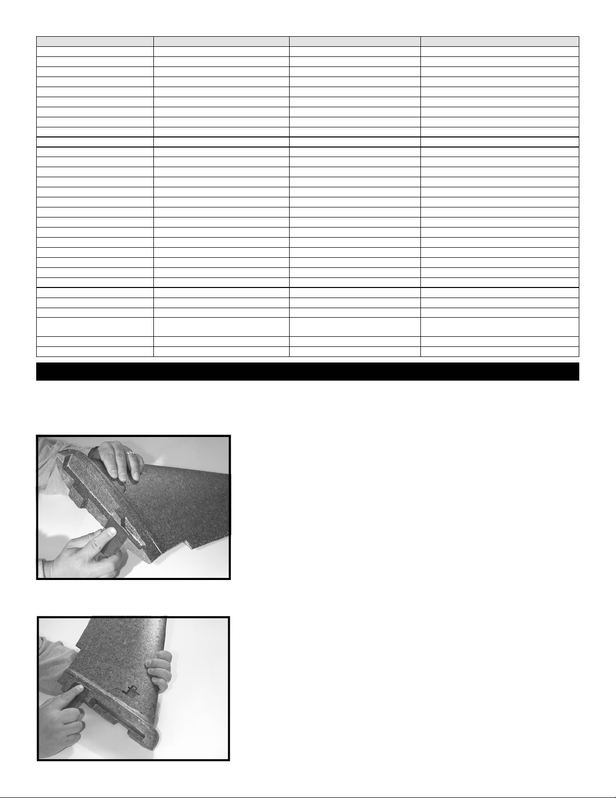
STEP 3: Using the supplied 2” x 4”, 120 grit screen cloth, carefully
sand the tips of the wings where the winglets will be bonded to the
wing halves.
STEP 4: Using rubbing alcohol and a soft, clean cloth, thoroughly
clean the wing halves all over to remove sanding residue and other
contaminants. A good cleaning will improve the bond obtained when
applying adhesives and adhesive tapes to ARCEL(TM).
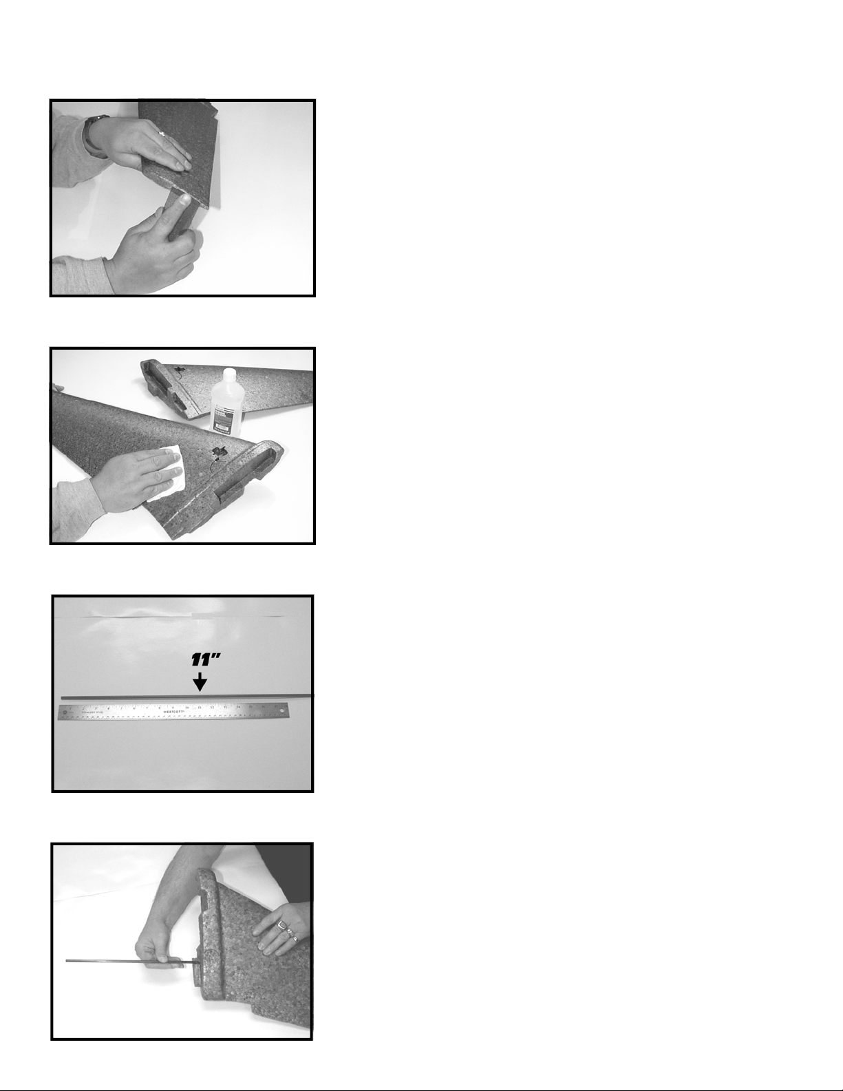
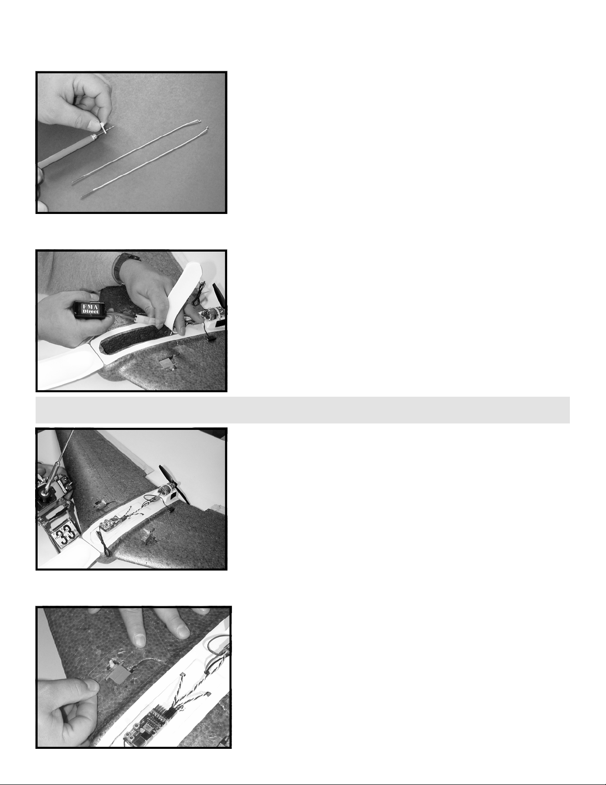
STEP 5: The new improved RAZOR kits and ARF’s now come with a
pre-cut, 22” long, 5.5mm diameter carbon fiber arrow shaft. The shaft
has been incorporated into the model as a wing spar to further en-
hance wing strength during high powered aerobatics and the occa-
sional but often unavoidable crash. Locate the rod in your kit and
mark the center at 11” using a felt marker.
STEP 6: Dry fit the shaft into the pre-drilled hole in the left wing
panel as shown. Make sure that there is no problem pushing the
shaft into the wing section until the mark you made in STEP 5 meets
the center line of the fuselage. Once you are satisfied with the fit, re-
move the shaft, and mix up a modest portion of epoxy. Hold the wing
so that the wing tip is facing the floor and dribble the epoxy down
into the hole using a popsicle stick or the like. Also coat one half of
the shaft itself. Fit the shaft back into the hole all the way to the cen-
ter mark and wipe away any excess glue.

6
STEP 7: FMA Direct recommends 5 minute epoxy for joining the
RAZOR wing halves. Review STEP 8 before continuing. Test fit the
wing halves to verify proper installation of the wing spar and correct
alignment of all parts. Observe where the wing sections contact each
other so that you know where to apply adhesives. Mix a large
amount of 5 minute epoxy. Start by holding the right wing upright
and dribbling epoxy down into the hole for the spar. Next, coat the
rod protruding from the left wing panel. Finally, apply approximately
1/16” thick to the inside of the right wing half as illustrated. Include
adhesive in the slot where the horizontal “key” joins the two wing
halves.
STEP 8: Hold the two wing halves together firmly as illustrated until
the adhesive cures. Keep a soft, alcohol-soaked cloth handy to wipe
away any excess adhesive. Once the adhesive has cured, you may
wish to sand the wing joint and apply a light weight filler if necessary.
TIP: For best results, use masking tape to mask off the joint on the two wing halves before applying adhesive. This will prevent glue from getting on
the visible portions of the airframe. Then after the two wing halves are joined, apply more tape to “capture” the glue and seal the joint!
BEFORE CONTINUING: The concept behind the FMA Direct RAZOR is to provide R/C or potential R/C enthusiasts with an inexpensive, highly
versatile, easy-to-build aircraft that can meet the various skill levels and tastes of many different pilots through the fourteen kit and ARF
versions available. In keeping with this concept, RAZOR does not require paint or special covering of any kind, thanks to the revolutionary
ARCEL(TM) foam and the injection molding process. In designing and flight-testing RAZOR, FMA engineers discovered that with the application
of a proprietary LEXAN(TM) tape used as a structural, quasi-spar, the airframe could withstand tremendous flight stress and impact. This
manual is intended for use with any of the slope, park, 400 class, or 600 class kits and ARFs available. All kits are supplied with two pieces of
0.005” thick LEXAN(TM) tape to be used for hinging the elevons and also for the hinge that joins the equipment tray to the canopy. The slope,
park, and 400 class kits are supplied with four pieces of 0.010” thick LEXAN(TM) tape for structural spars. The 600 class kits include two
additional pieces of 0.010” thick LEXAN(TM) tape for added support at high speeds. It is important that you locate and identify the different
thickness adhesive tapes supplied so that you use the proper tapes during assembly. Furthermore, unlike other foams, ARCEL(TM) is not
attacked by most paint types. For best results, if you intend to paint your RAZOR, use Krylon(TM) enamel from your local hardware store. Be
sure to apply a light coat of primer on the airframe before adding colors. Mist on one or two fine coats of pigment. Use only enough paint to
add color. Too much paint and you will add excess weight and possibly warp the foam wings. If you intend to paint your RAZOR, be sure to
carefully review the following CAUTION:
STEP 9: Steps 9 and 10 apply to 600 class kits only! If you do not
have a 600 class kit, please proceed to step 11. If you have a 600 class
kit, please locate one of the six pieces of 0.010” (thick) LEXAN(TM) tape.
Using a measuring stick, mark 4 inches off the tape. Using scissors,
cut the tape straight across. You will end up with a 20” piece of tape.
Mark the center of the tape.
CAUTION: PLEASE NOTE THE FOLLOWING - WHILE ARCEL(TM) IS NOT ATTACKED BY MOST PAINTS, THE PROPRIETARY LEXAN(TM) TAPE
USED IN ASSEMBLY IS! IF YOU INTEND TO PAINT YOUR AIRPLANE, COMPLETE ASSEMBLY OF THE RAZOR PER THE MANUAL, THEN USE A
PAINTABLE TAPE TO MASK OVER THE LEXAN TAPE USED IN ASSEMBLY TO PREVENT ANY PAINT FROM COMING IN CONTACT WITH THE
LEXAN TAPE. THIS INCLUDES THE TAPE HINGE BETWEEN THE TRAY AND CANOPY WHICH IS SUSCEPTIBLE TO DAMAGE FROM PAINTS
AS WELL! IF PAINT COMES IN CONTACT WITH THE LEXAN(TM) TAPE, THE TAPE WILL BECOME BRITTLE AND WILL TEAR OVER TIME.
600 CLASS ONLY

7
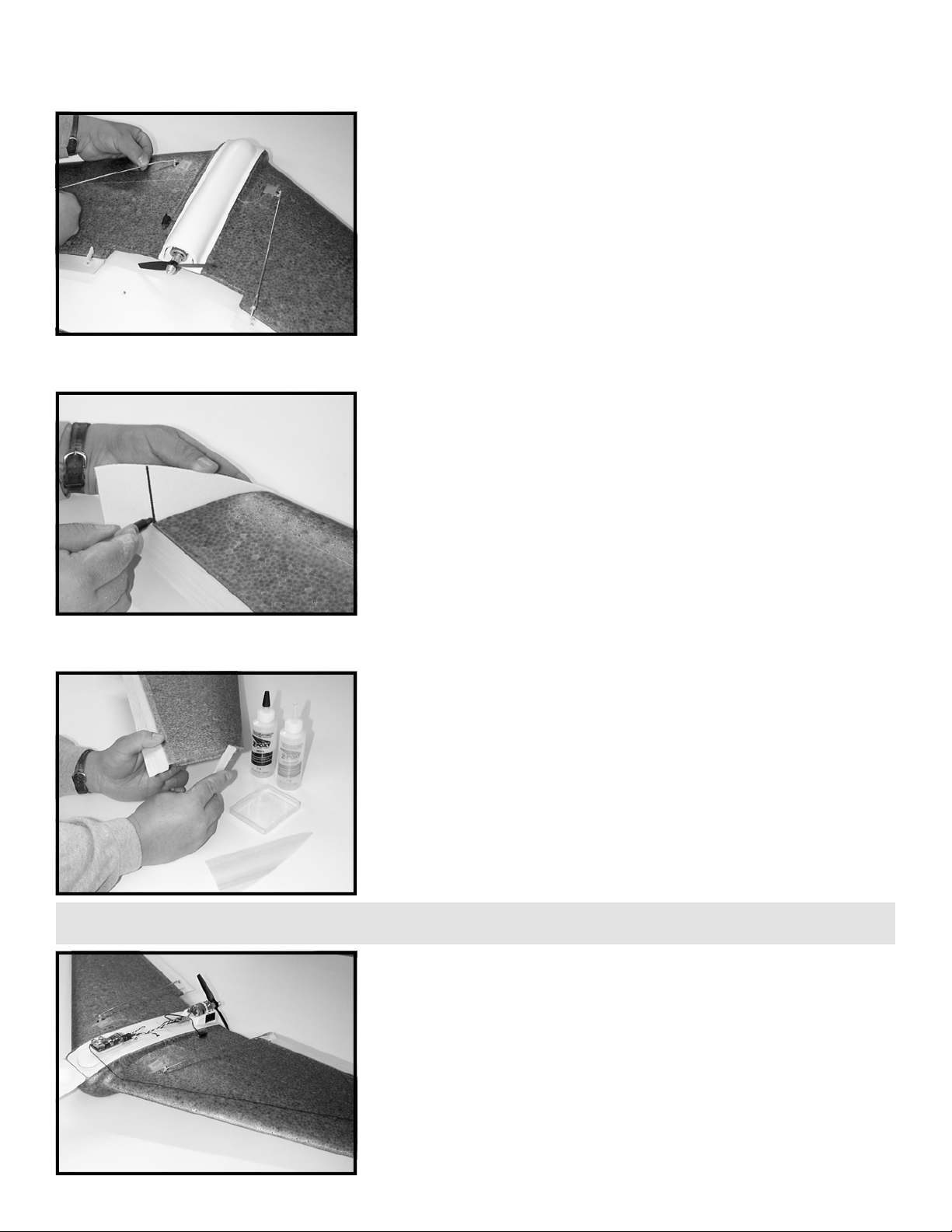
STEP 10: If you have a 600 class kit, apply the 0.010” x 20” tape you
prepared in STEP 9 to the aircraft as illustrated. Please note, the tape
shown in this photo is only for positioning. You will need to remove
the adhesive backing before installing the tape. Align the center mark
you made in STEP 9 with the joint line on the fuselage. Position the
edge of the tape approximately 1/4” from the trailing edge of the
wing as shown. When applying the LEXAN(TM) tape, rub the tape into
the wing vigorously using your thumb or a blunt object such as a
screwdriver handle. Note: the very-high-bond adhesive will “cure” to
about 50% of its bonding strength immediately. Full strength will be
attained within 24 hours.
STEP 11: Using a sharp hobby knife, cut the fuselage to extend the
servo wire slots straight through the walls of the fuselage and into
the battery compartment. These slots should be about 1/8” deep.
When you install the servos, the servo wires will pass under the
equipment tray and enter the fuselage through the walls of the
battery compartment. This arrangement ensures that the servo wires
will be well concealed, protected and will not impede the air flow
over the wings.
STEP 13: The equipment tray and canopy supplied with your kit are
rough cut about 1/4” outside the final shape required. Using scissors,
a hobby knife, or tin snips, trim the outside of the plastic equipment
tray and canopy to shape along the ledge that is molded into the
parts. It works best to hold the assemblies upside down. Be careful
when cutting the tray to leave the 1/4” lip on the back of the part.
This lip increases the strength of the part and also aids in lining up the
part during installation. After you have cut the parts to shape,
smooth the edges using sand paper.
STEP 12: Insert the servos into the molded slots in the wings. Using
a dowel rod or the like, press the servo wires into the servo wire slots
in the wing as illustrated. Do not use a screw driver or other sharp
instrument to install the servo wires or you may cut the wires.
TIP: When using a hobby knife, always make certain to cut away from yourself and your other hand to prevent injury!
600 CLASS ONLY
8
STEP 15: Position the plastic equipment tray right-side-up on a
cutting board. Using a sharp hobby knife, trim the outside edge of the
battery hatch. Cut the edge along the base of the tray so that when
the battery hatch is shut, the edge of the hatch will rest on the top of
the fuselage. Do not cut the hatch along the top of this ledge or the
hatch will cave into the battery compartment when flight pack
equipment is mounted on top of it.
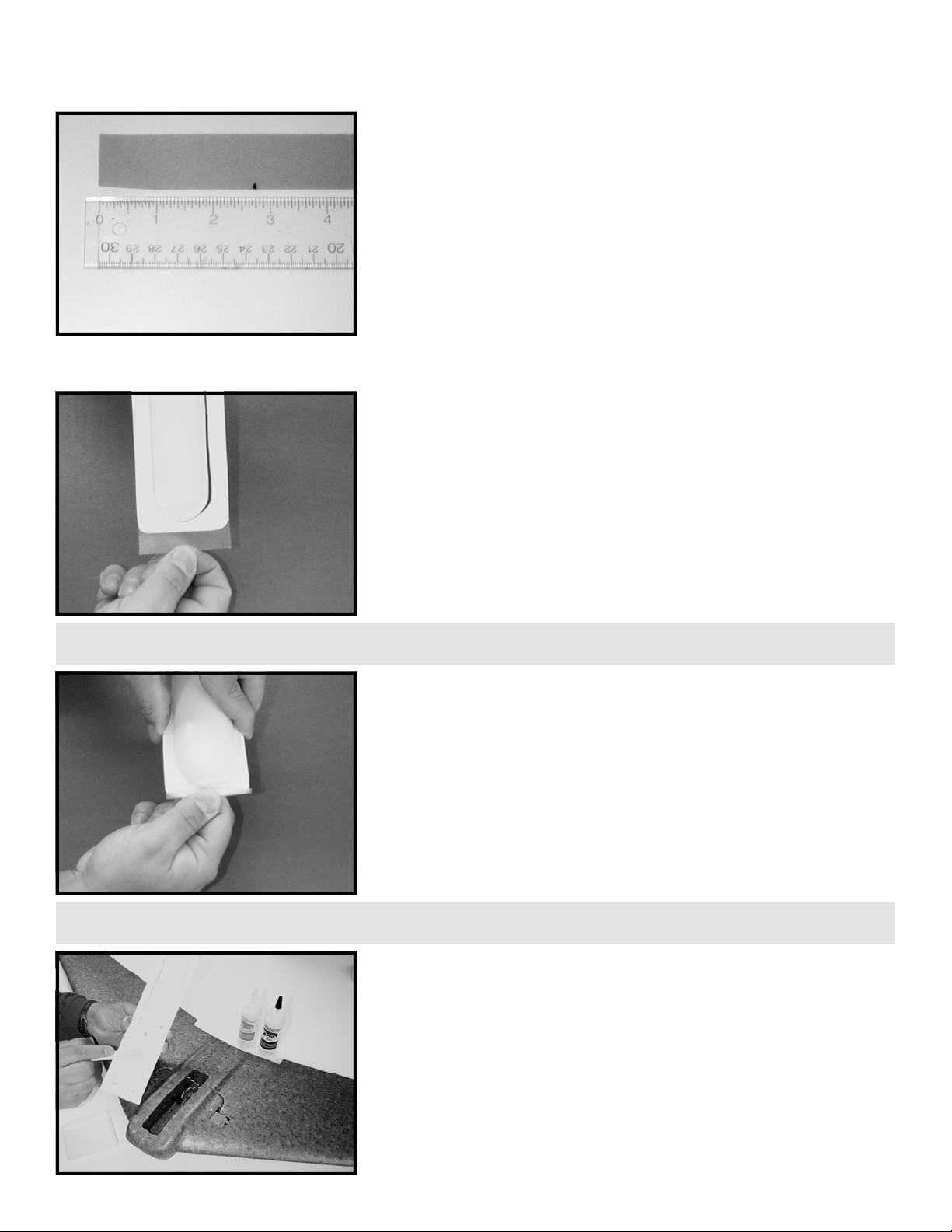
STEP 14: Trim the back face of the canopy out to allow the motor and
prop assembly to protrude from the back of the airframe. Cut to
within 1/8” of the edge so that the part remains strong. Do not cut on
the edge or the part will be too flimsy and may tear over time.
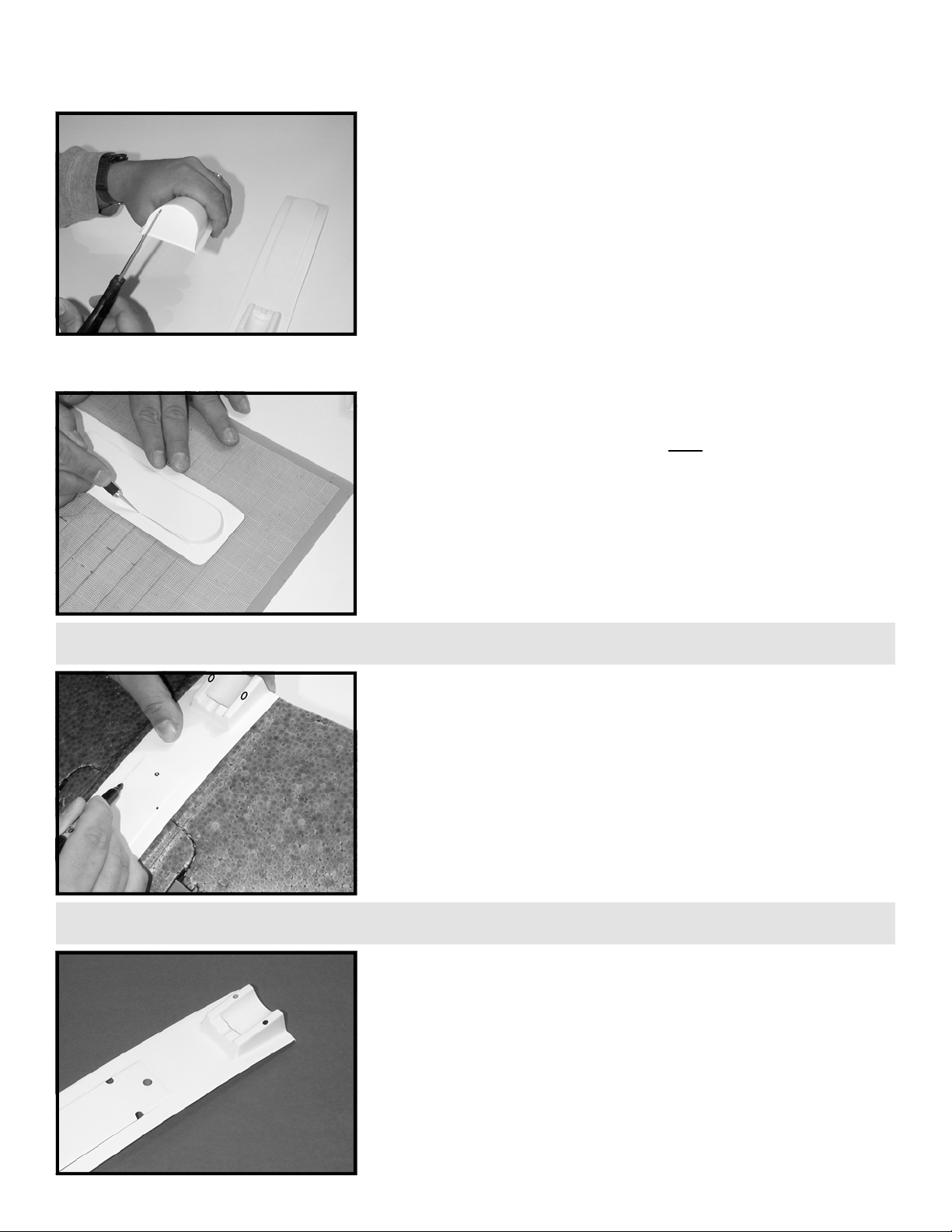
STEP 17: Use a sharp hobby knife to cut the holes and slots in the
equipment tray as marked in STEP 16. When you are done, the tray
should appear as illustrated.
TIP: If you are assembling a 600 “Performance” ARF, the hole in the back of the battery hatch must be large enough to accept the supplied Deans
Ultra connector.
STEP 16: Position the equipment tray on the fuselage temporarily.
Using a fine tip marker, mark the following places on the tray as
illustrated:
• mark for two holes on the centers of both ledges of the motor
mount to accept the nylon tie that holds the motor to the tray.
• mark for one hole near the back center of the battery hatch to
allow for the battery wires to pass through from the ESC unit.
• mark for two slots on the outside edges of the battery hatch that
will allow for the servo wires to pass through from the battery
compartment to the receiver to be mounted on the top of the
battery hatch.
TIP: Electric drills and Dremel tools make cutting holes in the plastic parts much easier if you have access to them.
9
STEP 19: Remove the adhesive backing from the tape hinge prepared
in STEP 18. Hold the equipment tray right-side-up in one hand. With
the other hand, install the tape to the bottom front of the equipment
tray. Allow about 1/2 the width of the tape to protrude from the front
edge of the tray, sticky side up.
STEP 18: Locate one of the two pieces of 0.005” (thin) LEXAN(TM)
tape. Mark the tape at 2 3/4”. This small piece of tape will be used to
hinge the canopy to the equipment tray for easy access to flight pack
and propulsion equipment. Cut the tape straight across.
STEP 20: Place the canopy on the equipment tray. Hold the assembly
right-side-up and carefully wrap the tape hinge over the top of the
canopy as in the illustration. The thin tape easily conforms to the
shape of the canopy so there is no need for cutting the tape around
the “bubble” of the canopy. Turn the tray/canopy assembly up-side-
down and trim away the excess tape that extends under the battery
hatch.
STEP 21: Sand the bottom of the equipment tray/canopy assembly
so that the adhesive bond will be strong. Mix a modest amount of 5
minute epoxy and apply a thin layer to the underside of the
equipment tray in the places where the tray will touch the fuselage.
Avoid getting adhesive on the servo wires. Mount the tray to the
fuselage and hold or tape in place until the adhesive cures.
TIP: As an alternative to using the LEXAN™ as a hinge, you may also attach the canopy at the front using hook and loop fastener.
TIP: Some customers have expressed having problems routing the nylon motor tie (shown in STEP 25) into the tray after the tray is installed. To
make it easier, you may wish to consider feeding the tie through the holes before gluing down the tray in STEP 21 below.
10
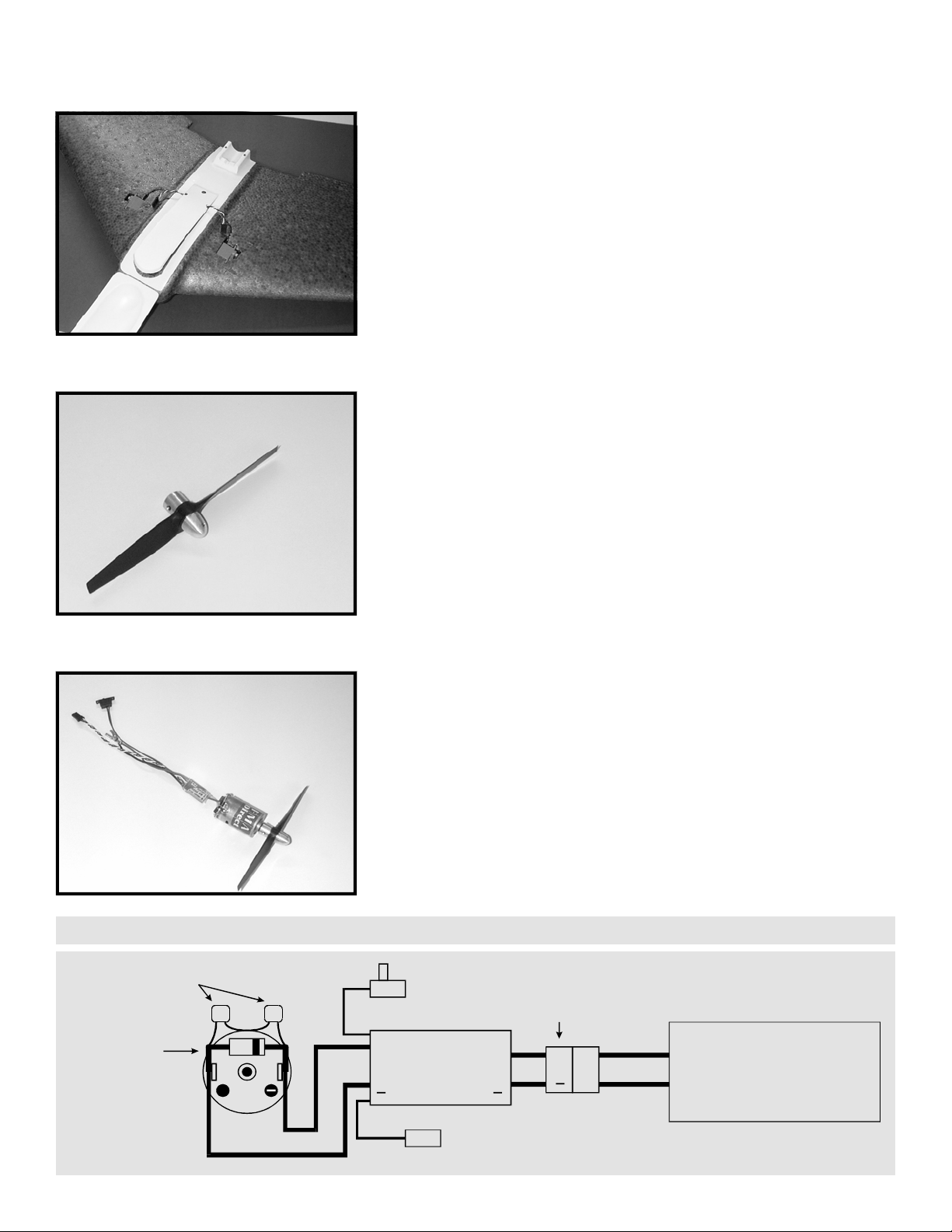
STEP 23: Locate the propeller and propeller adapter shaft, spinner
and set screws. Install the propeller onto the propeller adapter shaft
so that the propeller “pushes” air away from the back of the wing.
This will be backwards from the normal “puller” type installation
where the motor is mounted on the nose of the airplane. Verify
proper installation of the propeller by checking to see that any printed
information such as prop size or brand name is mounted on the side
of the prop away from the spinner. Install the spinner and hand
tighten using a hex wrench or small screwdriver shaft as a handle
through the hole in the spinner. Install the two set screws in the sides
of the propeller adapter shaft being careful not to cross thread.
STEP 22: Feed the servo wires up from the battery compartment,
through the battery hatch slots as in the illustration. Your finished
hatch/canopy assembly should appear as shown. The battery hatch
flips back to allow access to the battery. When the battery hatch is
closed, the canopy is free to flip back over the tray, capturing the
battery hatch and covering the flight pack and propulsion equipment.
STEP 24: The motor pack that shipped with your ARF is made up of
the ESC, the motor, capacitors, Shottky barrier diode, and wiring, pre-
assembled and ready for installation. If you are not using an FMA
Direct motor pack, please refer to the diagram following this step for
proper connection of ESC / motor. Install propeller assembly to the
motor shaft. Press the assembly until it is within 1/16” to 1/8” of the
motor face. Tighten the two set screws using the proper hex wrench.
+
0.01UF MOTOR
CAPACITORS
SHOTTKY DIODE
CATHODE (BAND)
TO ESC + ALWAYS ELECTRONIC
SPEED CONTROL
(ESC)
MTR
BATT
++
+
MALE
PLUG
RCVR
PLUG
ESC
POWER
SWITCH
POWER
PACK
BATTERY
RED
WIRE
BLACK
WIRE
MOTOR
MOTOR PACK CONNECTIONS

11
STEP 26: Locate two pieces of the 0.010” (thick) LEXAN(TM) tape. On
each piece of tape, mark one side at 3”; mark the other side at 3.5” as
illustrated. Cut each of the tapes across the equal but opposite
angles as in the illustration. You will end up with two short pieces of
tape to be used for holding the servos in place and two longer pieces
that will serve as the structural spars for the top sides of each wing
half.
STEP 25: Assemble the motor pack to the equipment tray as
illustrated. Feed the nylon tie through the holes you cut in the motor
mount. Pull the nylon tie tight so that the clamp is resting closest to
either hole and cut off the excess.
STEP 27: Steps 27 and 28 apply to 400 class kits only! If you do not
have a 400 class kit, please proceed to step 29. If you have a 400 class
kit, locate the four pieces of 0.010” LEXAN(TM) tape provided. Two of
these have been cut slightly shorter in STEP 26 above and are angled
on one end. Mark and cut off 6” from the square ends of all four
pieces of tape. The 6” pieces will provide added structural support to
the wing where the prop cutout is molded into the trailing edge of the
wing. The two shorter pieces with the angle cuts on one end will be
used for structural support for the top of the wing. The two longer
pieces will be used for structural support for the bottom of the wing
where the most stress occurs in flight during loops.
STEP 28: This illustration shows the placement of the structural and
servo tapes prepared in STEPS 26 and 27 for a 400 class kit. Do not
install the tapes at this time, but test the placement of each as
follows. The long tape should be positioned so that the end closest to
the fuselage begins where the wing joins the fuselage and is centered
over the servo wire slot. The end closest to the wing tip should be
centered on the wing panel. The servo tape should butt up against
the structural tape and center over the servo. The front of this tape
should extend 1” beyond the servo case (toward the leading edge). If
required, trim the angle cuts slightly. Put the short servo tapes aside
as these will not be installed until radio installation is complete!
400 CLASS ONLY
400 CLASS ONLY

12
STEP 29: This illustration shows the placement of the structural and
servo tapes prepared in STEP 26 for a 600 class kit. Do not install the
tapes at this time, but test the placement of each as follows. The long
tape should be positioned so that the end closest to the fuselage
begins where the wing joins the fuselage and is centered over the
servo wire slot. The end closest to the wing tip should be centered on
the wing panel. The servo tape should butt up against the structural
tape and center over the servo. The front of this tape should extend
1” beyond the servo case (toward the leading edge). If required, trim
the angle cuts slightly. Put the short servo tapes aside as these will
not be installed until radio installation is complete!
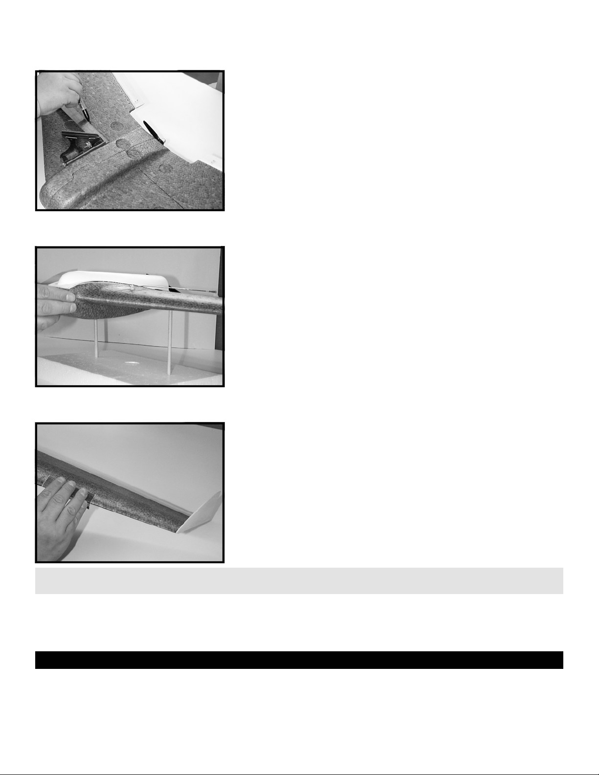
STEP 30: Hang the fuselage and one wing half over the edge of the
table as illustrated. Remove the backing from the structural tape
prepared earlier and place the tape as detailed in the above steps.
Make certain the wing is flat on the table top so no warping of the
wing can occur. Seal the tape tightly to the wing using your thumb or
a blunt object such as a screwdriver handle. Remember, the very-
high-bond adhesive will “cure” to about 50% of its bonding strength
immediately. Full strength will be attained within 24 hours. Repeat
this step for the top of the other wing.
STEP 31: STEP 31 applies to 400 class kits only! If you do not have a
400 class kit, please proceed to STEP 32. This illustration shows the
placement of the structural tapes prepared in STEPS 27 for the bot-
tom of a 400 class kit. Locate the remaining pieces of 0.010” (thick)
LEXAN(TM) tape. Note: when preparing the tape for installation, you
will want to trim the inside end to match the angle of the fuselage.
The bottom side structural tapes should be centered along the wing
core over the span of each wing.
STEP 32: This illustration shows the placement of the structural tapes
for the bottom of a 600 class kit. Locate two of the remaining pieces
of 0.010” (thick) LEXAN(TM) tape.* Note: when preparing the tape for
installation, you will want to trim the inside end to match the angle of
the fuselage. The bottom side structural tapes should be centered
along the wing core over the span of each wing.
* Note: if you have a 600 Class kit, your kit will contain one
additional piece of structural tape to be installed in STEPS 34 and 35.
600 CLASS ONLY
400 CLASS ONLY
600 CLASS ONLY
13
STEP 33: Turn the airframe upside down and hang the fuselage and
one wing half over the edge of the table as illustrated. Remove the
backing from the tape and place the tape on the bottom of the wing
as detailed in the previous steps. Make certain the wing is flat on the
table top so no warping of the wing can occur. Seal the tape tightly
to the wing using your thumb or a blunt object such as a screwdriver
handle. Repeat this step for the bottom of the other wing.
STEP 34: Steps 34 and 35 apply only to a 600 Class kit. If you do not
have a 600 Class kit, proceed to STEP 36. If you have a 600 Class kit,
locate the remaining piece of 0.010” LEXAN(TM) tape. Mark the center
of the tape and cut straight across.
STEP 35: This illustration shows the placement of the 600 Class,
additional bottom structural tapes prepared in STEP 34. Remove the
adhesive backing from the structural tape. Turn the airframe upside
down and hang the fuselage and one wing half over the edge of the
table as in STEP 33. Remove the backing from the tape and place the
tape on the bottom of the wing as illustrated. Make certain the wing
is flat on the table top so no warping of the wing can occur. Seal the
tape tightly to the wing using your thumb or a blunt object such as a
screwdriver handle. Repeat this step for the bottom of the other
wing.
STEP 36: Feed the two power wires
from the ESC through the hole in the
battery hatch. Locate the plastic,
male, Tamiya type shell. Install the
shell to the power wires by pushing
the wire leads with the connector
pins through the back of the shell as
illustrated. Be sure to maintain
proper polarity of the black and red wires as shown in the diagram.
The pins will “click” into place when they are properly seated. Test
the connection by lightly tugging on the wires after installation.
RED WIRE BLACK WIRE
Connector Polarity
TIP: STEP 36 does not apply to the 600 “Performance” RTF as you have already made the hole large enough to accommodate the entire Deans plug.
600 CLASS ONLY
600 CLASS ONLY
14
STEP 37: Open the canopy. Connect the two servo leads to the
receiver outputs. Connect the ESC lead to the receiver. Don’t worry if
you are not sure which channels are the correct ones for now, you will
double check this in final installation. Using double-sided foam tape
(not supplied), tape down the ESC, power switch and receiver as
illustrated. Cut the supplied hook & loop fastener material in half and
apply to the sides of the motor mount as shown. Remove the
adhesive backing from the outside of the hook & loop fastener.
STEP 38: Carefully close the canopy. At the back, press one side
down against the tray and then press against the hook & loop
adhesive backing. Pull out on the other side of the canopy as you
press it down against the tray and then against the hook & loop
adhesive backing. See illustration.
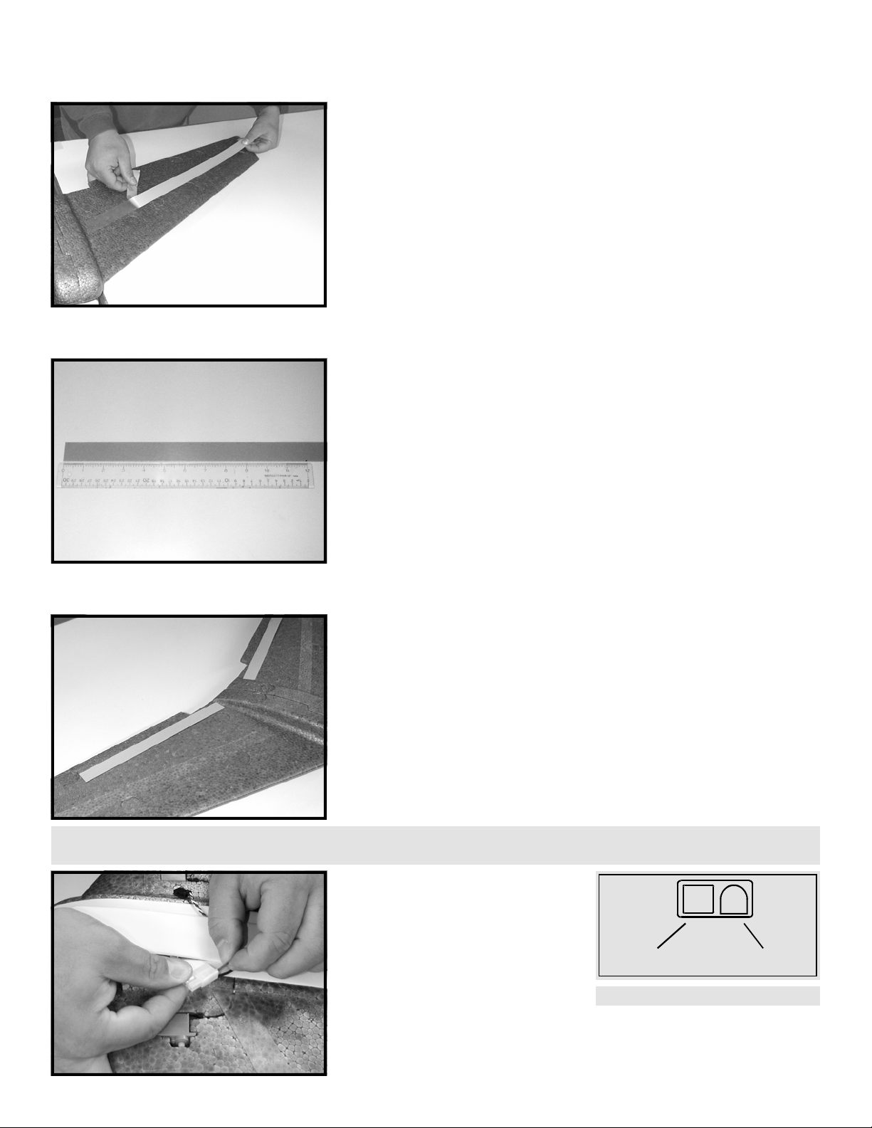
STEP 39: The elevons that come with your kit are pre-cut to a shape
that will facilitate the use of the custom LEXAN(TM) tape as a hinge.
The elevons are cut at an angle on the leading edge so that they will
not bind on the trailing edge of the wing when down elevator is
applied. Make sure that you install the elevons with the cut side
down. Hold the elevon up against the trailing edge of the wing.
Then, using a straight edge, mark the in-board side of the elevon at an
angle to match the cut-out for the propeller clearance slot in the back
of the wing. See illustration.
STEP 40: Continue holding the elevon up against the trailing edge of
the wing. Then, using a straight edge, mark the out-board side of the
elevon 1/8” in from the wing tip and at an angle to match the wing
tip. See illustration. Repeat STEPS 39 and 40 for the other elevon.
TIP: To improve the appearance of the joint between the elevons and trailing edge and to reduce drag, use a sanding block to round off the sharp
edge on the bottom of each elevon.

15
STEP 41: Locate the two strips of 0.005” (thin) LEXAN(TM) tape. Cut
one piece of tape to the length of the elevon. Set the elevon right-
side-up (leading edge angle down) and facing you. Remove the
adhesive backing from the tape and apply the tape to the elevon so
that 1/2 the width of the tape hangs off the top leading edge of the
elevon.
STEP 42: Hold the leading edge of the elevon up to the trailing edge
of the wing and position it so that the in-board side of the elevon is
aligned with the propeller cut-out slot. Droop the back of the elevon
downward as if full down elevator were being applied. Fasten the
elevon to the wing and seal the tape tightly to the wing using your
thumb or a blunt object such as a screwdriver handle. When you are
finished, the elevon should be hinged and free to move upwards or
downwards with ease. Repeat STEPS 41 and 42 for the other elevon.
STEP 43: Make a small mark on the leading edge of the elevon at 3/4”
from the in-board side of the elevon. Extend a straight edge from the
end of the servo output shaft to the small mark you just made. Then
extend the small mark along the angle of the straight edge 1/4”
toward the trailing edge of the elevon. Repeat for other elevon.
These lines will be used to align the control horns installed below.
STEP 44: Position the control horn so that the vertical arm of the
horn is aligned with the mark you made in STEP 43. Make sure that
the holes in the control arm are directly above the elevon/wing hinge
joint. Using a small hand drill or screwdriver, mark for and make
holes in the elevon using the holes in the base of the control horn as a
guide. Hold the control horn plate under the elevon and fasten the
control horn using the screws provided. Repeat for the other control
horn.
TIP: To prevent injury, use a pair of heavy diagonal cutters or a Dremel tool with a grinding wheel to cut off the excess from the control horn screws
protruding underneath the wing.
TIP: It is always a good idea to cover your elevon and winglet surfaces with covering material before installation to prevent moisture from getting into
the wood and causing warping or adding weight.
16
STEP 45: Using a small bit that is slightly smaller than the outside
diameter of the pushrods, open up the second hole down on the servo
arms to accept the pushrods. The fit should be tight to prevent any
slop in the linkages.
STEP 46: Make sure the ESC power switch is off. Open the canopy
and battery hatch, and install the fully charged 7 cell battery power
pack. Do not turn the power switch on at this time.
STEP 47: Position the servos up-right in the servo cut-outs. If
applicable, install the receiver crystal in the receiver and check that
the dip switches are set in accordance with the receiver manual. Be
certain the propeller is free of obstructions! Set transmitter throttle
and throttle trim controls full off, then turn on transmitter. Turn the
ESC power switch on being careful of the propeller. Check to make
sure you have the servos and ESC plugged into the correct channels
on the receiver; i.e., throttle controls throttle, elevator and aileron
control the servos. When everything is working, install and center the
servo output arms facing in as illustrated. See the section titled
“SETTING UP AND FLYING THE MODEL” for instructions on set up.
STEP 48: Put the servos back into the servo cut-outs and tape in
place using the two short pieces of tape prepared in STEP 26.
TIP: While the following steps are illustrated with the propeller installed, it is much safer to remove the propeller before applying power and leave it off
during initial setup until you’re ready to fly the airplane.
17
STEP 49: Screw the clevis onto the pushrods. Install the pushrods to
the servo output arms from the out-board side of the servo. Your kit
contains one left and one right pushrod. Before snapping the clevis to
the control horn, adjust the length of the rod so that when the
pushrods are installed, the elevons are set for 2 degrees up elevon.
You can judge 2 degrees as follows: the horizontal (level) axis of the
airframe is along the part line of the molded part. The part line can be
identified by small protrusions of foam that outline the entire
airframe; i.e. leading edge, trailing edge, wing tips. Hold the aircraft
such that the part line of the mold is parallel to the ground. The back
of the elevons should rise about 1/16” above this imaginary plane.
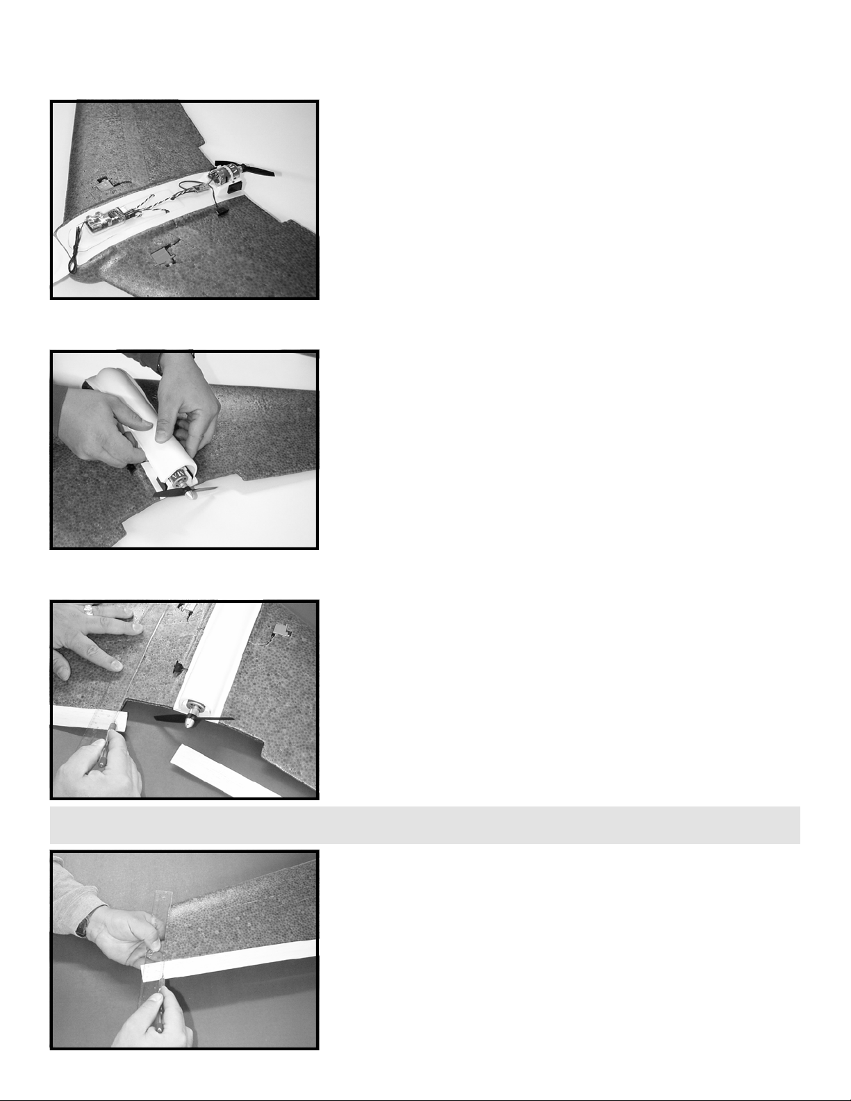
STEP 50: Round-off the top edge of the winglets. The shape of the
winglet on 400 Class kits is not critical. You may install them as is, or
you may change the size and shape to suit your tastes. For all 600
Class kits, it is mandatory that you reduce the length of the winglet
so that it does not protrude beyond the trailing edge of the wing. For
600 Class kits, hold the winglet up to the wing tip, mark and cut the
length of the winglet down as illustrated. Cutting down the winglets
for 600 Class models will greatly improve flight handling at slow
speeds, helping to prevent tip stall and snap roll.
STEP 51: Mix a modest amount of 5 minute epoxy and apply to the
wing tip. Attach winglet to wing tip and align the underside of the
winglet to match the underside of the wing airfoil. Hold or tape in
place until glue sets. Repeat for other winglet.
STEP 52: Cut a small slot 1/8” deep and 1/2” long in the top of the
wing in front of the servo and directly in line with the front of the
receiver. Press the antenna into this slot using a small blunt dowel so
as not to damage the antenna wire. Use a small piece of 0.005” (thin)
LEXAN(TM) tape to “capture” the antenna in the slot but allow it to
move freely back and forth through the slot. This arrangement will
keep the antenna from coming in contact with the servo mechanism
but will allow you to open the battery hatch to change/charge
batteries. Route the antenna over the top of the wing toward the
back of the winglet. Drill two small holes in the winglet just ahead of
the trailing edge of the wing. Loop the antenna through these holes.
600 CLASS -
400 OPTIONAL
TIP: Optional antenna routing...drill a small hole through the wing about 1” back from the leading edge and directly opposite the back of the receiver.
Route the antenna to the underside of the wing and angle back to the outboard trailing edge. Drill another small hole there and route antenna back up.
18
STEP 53: Place the aircraft upside down. Using a ruler, measure back
exactly 7 inches from the point where the leading edge of the wing
intersects the fuselage and make a small dot on the underside of the
wing. This measurement is critical as it will determine the CG of the
airplane, so take your time. Using a square, extend a line from this
point you just made perpendicular to the fuselage. If you don’t want
to mark on the airplane, use tape so you can remove it later.
STEP 54: With all equipment installed (including the battery), and the
canopy shut, check to make sure the plane balances within ±1/4” of
the CG line marked in STEP 53. The illustration shows the plane
balanced on two dowel rods inserted into a piece of foam for this
purpose. If the airplane was constructed in accordance with this
manual, it should balance on the CG with the batteries pushed all the
way to the front of the battery compartment. If your airplane is nose
heavy, slide the battery back until it balances. If the plane is tail
heavy, consider cutting down the winglets or sanding the elevons
before adding ballast to the nose. With the CG set properly and with
2 degrees of up elevon, the plane should glide level.
STEP 55: This step is optional on all 400 Class models but mandatory
on all 600 Class models. The 600 Class aircraft are heavier and the
wing loading is higher. To greatly improve flight handling at slow
speeds and help to prevent tip stall and snap roll, the outer 1/2 to 2/3
of the leading edge of the wing and the front of the winglet must be
sanded round. Rounding the outside of the leading edge ensures that
if the airplane begins to stall at slow speed, the wing will stall at the
center rather than at the tips, helping to prevent snap roll and making
the plane recover faster and with less difficulty. For best results, sand
about 1/4” radius into the sharp leading edge and fair it in toward the
center of the wing.
TIP: Rounding the leading edge of the wing is a trade-off between top speed and maneuverability. While a sharper leading edge will improve top
speed, a rounder one will improve handling. STEP 55 is about the best compromise to give good handling without a noticeable speed reduction.
This completes the assembly portion of the manual. If you elect to apply the FMA Direct decals or other
adornments to RAZOR, it is a good idea to clean the foam surface with alcohol before you proceed. The next
section includes basic setup information and tips for flying RAZOR based on extensive flight testing conducted by
FMA Direct engineers.
SETTING UP AND FLYING THE MODEL
OVERVIEW
If you are new to radio control, it is important that you seek the help of an experienced modeler to help you set up and learn to fly
your new RAZOR. The hardest part of learning to fly is adjusting the control surfaces and “trimming” out the model during the initial
flights. Also, no matter what your skill level, it is always a good idea to have another modeler around the first time you fly the
airplane to launch it for you. Until the airplane is trimmed to fly straight and level with little transmitter stick motion, launching can
be a bit tricky. A flying wing has many advantages over a normal design in terms of efficiency. “Tailless” wings can be built much
600 CLASS -
400 OPTIONAL

19
lighter than normal aircraft so that for the same wing area, the wing loading is much lower and the aircraft can perform better with
smaller motors and propellers. In terms of controlling the airplane, the major difference between a flying wing and a standard
aircraft design is that both elevator, or “pitch” control (for up and down) and aileron (for banking right and left to turn the airplane)
are merged into two flight surfaces instead of three. This convergence of elevator and aileron control is termed “elevons”. In order
to fly RAZOR, you are required to have either 1) elevon mixing capabilities in your transmitter, or 2) an on-board mixing unit such as
the FMA Direct MX80 installed in the aircraft that is capable of elevon mixing. Another difference inherent to RAZOR is the absence of
rudder control which is the vertical control found on normal aircraft and allows the pilot to create turns by “yaw” which changes the
direction of the tail relative to the nose of the aircraft. All turns with RAZOR will be performed by banking the airplane left or right as
opposed to creating yaw. Once you get past the initial stages of set-up and trimming the model, RAZOR is easy to fly and capable of
performing most basic aerobatic maneuvers not requiring rudder control. The slope, park, and 400 Class models are designed to fly
at slow to moderate speeds, are great for thermaling, gliding, and modest aerobatics. The 600 Class models are designed for higher
speed, better maneuverability and greater piloting skill levels.
QUICK REVIEW
This section assumes that you have successfully completed the assembly portion of the manual. You have completed installation of
the propulsion equipment (STEPS 23 - 25, 36), flight pack equipment (STEP 37) and installed the battery (STEP 46). You have
properly installed the servo arms and completed initial radio setup (STEP 47). You have installed pushrods and control linkages and
have set the elevons for 2 degrees up elevator (STEP 49). Finally, you have marked and checked the CG (STEPS 53, 54) to ensure that
the plane balances properly.
SETTING UP ELEVON MIX
Make certain the aircraft is anchored, that the propeller is free of obstructions, and that the throttle control and throttle trim are set
in the full off position before you turn the transmitter and then the ESC power switches on. Follow the instructions provided with
your transmitter or with your on-board mixing unit to enable elevon mixing. Once you have successfully completed this step, the
following should occur:
1) Pulling back on the elevator control stick causes both elevons to move up.
2) Pushing forward on the elevator control stick causes both elevons to move down.
3) Pushing the aileron control stick right causes the right elevon to move up and the left elevon to move down.
4) Pushing the aileron control stick left causes the left elevon to move up and the right elevon to move down.
5) While holding full left aileron control, pulling back on the elevator control stick causes the right elevon to move up slightly while
the left elevon stays up.
PRE-FLIGHT CHECK AND RANGE TEST
Always perform the following pre-flight test before flying the model:
1) Make sure the propeller is free of all obstructions.
2) Make sure the throttle control stick and throttle trim lever are set in the full off position.
3) Turn the transmitter power on and then turn the ESC power switch on.
4) Verify that the transmitter controls the proper channels on the receiver; i.e., throttle control runs the motor as the propeller
“pushes” air away from the back of the airplane; elevator and aileron controls move the servos.
5) Perform the previous, numbered sequence under SETTING UP ELEVON MIX before each flight to verify that mixing is set up
properly.
6) With the antenna collapsed to the first section on the transmitter and the aircraft anchored and elevated several feet off the
ground on a non-conductive surface, walk away from the airplane moving the elevator/aileron stick(s) on the transmitter. At 100
feet, make certain the propeller is free of obstructions, and move the throttle control to full on. Check to see that you still have
full control of the flight surfaces. Throttle back quickly to avoid using up valuable battery power.
GLIDE TEST
Glide testing the airplane is always best when one person is launching the aircraft and another is controlling it. Determine the
direction of the wind. On a gentle slope, hold the airplane over your head and run slowly into the wind. Give the airplane a gentle
push with the nose pointing straight ahead and the wings level. Correct the flight path with the transmitter controls. If you are glide
testing a 600 Class aircraft, run faster and throw the plane harder as the airplane is heavier. Make adjustments to your trim settings
until the aircraft glides straight ahead with a gentle downward sink rate. Remember, if the aircraft pitches up and stalls, trim the
elevator control to add more down elevator. If the aircraft dives, trim the elevator control to add more up elevator. Make
adjustments to the flight control linkages until the correct glide test results are obtained with the trims set at neutral. Note: if you
are flying a 600 Class aircraft, be aware that you will most likely add more up trim in a glide test than is required for powered flight.
POWERED FLIGHT
Make sure your flying site has enough area to maneuver the aircraft without getting too close to roads, buildings, trees, or power
lines. 400 and 600 class RAZOR models are not intended as park fliers. They require a flying field the size of a football field or larger.
Never fly over the heads of spectators, and keep the aircraft in sight at all times. A radio control aircraft is a big responsibility and
should not be taken lightly. Even an experienced pilot has an occasional lapse of concentration or problems with his equipment.
For at least the initial flight, have an experienced R/C modeler launch or fly the aircraft for you. Determine the direction of the wind.
Power up the system as in the pre-flight check. We cannot stress enough the importance of keeping your hands clear of the
propeller at all times! Hold the airplane over your head, power the motor to full throttle, and run briskly into the wind. While
holding about 50% up elevator, give the airplane a strong toss with the nose pointing straight ahead and the wings level. Be sure to
pull your arm down and away from the airplane as you launch to clear the propeller! Correct the flight path with the transmitter
controls. If you are launching a 600 Class aircraft, run faster and throw the plane harder as the airplane is heavier. As you fly the
plane, make adjustments to your trim settings until the aircraft flies straight and level with the transmitter control stick centered.

20
Remember, if the aircraft pitches up and stalls, trim the elevator control to add more down elevator. If the aircraft dives, trim the
elevator control to add more up elevator. Upon landing, make final adjustments to the flight control linkages until the correct flight
test results are obtained with the trims set at neutral.
ADDING EXPONENTIAL OR DUAL RATES
Although neither function is required to fly the RAZOR successfully, extensive flight testing by FMA engineers has determined that
handling characteristics can be dramatically improved with the addition of exponential or dual rates on the aileron and/or elevator
controls. Begin with 50% exponential and increase or decrease to match your tastes. If you do not have this capability, try setting
up dual rates. Use low rates (elevon throws of 3/8” each direction, up and down) for the initial flights during trim-out and then move
to high rates (1/2” or 3/4” throws) once you are familiar with the flight characteristics of the airplane.
FLIGHT CHARACTERISTICS
Overall, you will find the RAZOR to be a satisfying and enjoyable airplane to fly. The slope, park, and 400 Class models are extremely
docile and easy to manage. They can fly very slowly and do not readily approach stall speeds. The 600 Class models are designed
for high speed! They require a higher skill level and because of the weight, they should be maintained at an airspeed significantly
higher than 400 Class, especially in turns. As with any flying wing design, the one inherent trait to watch out for is tip stalling. If you
have successfully completed the instructions relating to limiting this phenomenon in STEPS 50 and 55, you will be pleased with the
600 Class slow speed flight characteristics and stall recovery, but please realize that because of the weight of this aircraft, tip stalls
cannot be completely eliminated. With either class of RAZOR, if you should ever push the aircraft to the point of stall, the tendency is
for it to stall at the tip and then begin to spiral. Should this happen, pull back on throttle, allow your control sticks to neutralize, and
let the airplane recover itself. At the bottom of one complete spiral, add throttle slowly, gently pull back on the stick and regain level
flight. Finally, on a 600 Class model, when the battery runs down and the motor shuts off, release elevator control, level out the
plane and maintain your airspeed on approach!
STORAGE INSTRUCTIONS
Never store your airplane inside of your car on a hot summer day. This could cause the structural tape to shrink and thereby create a
warp in the wings. If wing warpage or bowing should occur, remove the structural tape from the wings and install new tape as per
the instructions provided in this manual. Never attempt to fly the airplane with warped or bowed wings! Also be aware that during
extreme cold conditions the adhesive tape used in assembly may lose some of its bonding strength.
CONVERTING AIRPLANE MODELS
If you purchased the slope soar model of the RAZOR, and later wish to convert it over to a 400 Class model, purchase a 400 motor
pack and a 7 cell 600AE battery. Follow the instructions in this manual for installation. If you purchased the 600 Class “Endurance”
model and later wish to upgrade to a “Performance” model, purchase the “Performance” 600 motor, a male and a female Deans Ultra
pigtail. Install the motor and connectors as per the MOTOR PACK diagram on page 10.
In addition to the following spare parts list available by calling direct or through your local hobby dealer, FMA Direct stocks a full line
of receivers, servos, batteries, speed controllers, chargers, etc. For fast charging RAZOR battery power packs, FMA recommends
charger models FC300 “MINIPULSE” or FC600 “VERSAPULSE”.
SPARE PARTS
SLOPE Class PN 400 Class PN 600 “Endurance” PN 600 “Performance” PN
AIRFRAME PARTS:
ELEVON PACK RZRELVPK RZRELVPK RZRELVPK RZRELVPK
WINGLET PACK RZRWNGLTPK RZRWNGLTPK RZRWNGLTPK RZRWNGLTPK
PLASTICS PACK RZR400PLASPK RZR400PLASPK RZR600PLASPK RZR600PLASPK
HARDWARE PACK RZR400HDWPK RZR400HDWPK RZR600HDWPK RZR600HDWPK
PUSHROD PACK RZRPRPK RZRPRPK RZRPRPK RZRPRPK
CONTROL HORN PACK CHNYLSM1PK CHNYLSM1PK CHNYLSM1PK CHNYLSM1PK
METAL CLEVIS PACK MCLEV2-56PK MCLEV2-56PK MCLEV2-56PK MCLEV2-56PK
ELEVON TAPE TAPEPK-LEX-005-1X24 TAPEPK-LEX-005-1X24 TAPEPK-LEX-005-1X24 TAPEPK-LEX-005-1X24
STRUCTURAL TAPE TAPEPK-LEX-010-1X24 TAPEPK-LEX-010-1X24 TAPEPK-LEX-010-1X24 TAPEPK-LEX-010-1X24
22” CARBON ROD CFS5.5X22 CFS5.5X22 CFS5.5X22 CFS5.5X22
PROPULSION PARTS:
MOTOR PACK N/A RZR400MTRPK1 RZR600MTRPK1 RZR600MTRPK2
MOTOR N/A MTR400-RS380PH MTR600-RS-550PF MTR600-RS-550SH
MOTOR CAPACITORS N/A C0.01UFPOLY C0.01UFPOLY C0.01UFPOLY
MOTOR DIODE N/A DSR504 DIR80SQ035 DIR80SQ035
ELEC. SPEED CONTROL N/A SC20 SC30 SC30
MALE CONN. ASSY N/A WW200-M02ASSY WW200-M02ASSY DNS-7091ASSY
PROPELLER N/A PROPPK-MAS-5.5X4 PROPPK-MAS-8X4 PROPPK-MAS-8X4
PROPELLER ADAPTER N/A PA400 PA600 PA600
FLIGHT PACK PARTS:
RECEIVER 202FM72 / 202AM72 202FM72 / 202AM72 202FM72 / 202AM72 202FM72 / 202AM72
SERVO S80 / S100 / PS30 /PS50 S80 / S100 / PS30 /PS50 S80 / S100 / PS30 /PS50 S80 / S100 / PS30 /PS50
FLIGHT PACK BATTERY SAN4C110 N/A N/A N/A
SWITCH HARNESS 210LFJ N/A N/A N/A
POWER PACK PARTS:
BATTERY PACK N/A SAN7C600AESTTAM SAN7C800ARSTTAM SAN7C800ARSTDNS
OPTIONAL BATTERY N/A SAN8C600AESTTAM SAN8C800ARSTTAM SAN8C800ARSTDNS
FEMALE CONN. ASSY N/A WW200-F02ASSY WW200-F02ASSY DNS-7092ASSY
Table of contents
Other FMA Toy manuals


