FMI VJCAT42/50S User manual

OWNER’S OPERATION AND INSTALLATION MANUAL
INDOOR WOOD BURNING (V)GCAT42/50(H)A SERIES
INDOOR/OUTDOOR WOOD BURNING (V)JCAT42/50(H,S)
SERIES FIREPLACES WITH INSULATION
PFS
®
USC
ICC-ES #ESR-2542
For more information, visit www.fmiproducts.com
These models meet the EPA Wood Burning Fireplace
Program Phase 2 emission level. NOTE: To ensure proper
replace operation, the catalyst should be replaced at a
minimum of 3 years and a maximum of 5 years.
SAVE THIS BOOK
This book is valuable. In addition to instructing you
on how to install and maintain your appliance, it also
contains information that will enable you to obtain re-
placement parts or accessory items when needed. Keep
it with your other important papers.
This replace is approved for use as a wood burning
replace or for use with a vented gas log approved to
ANS Z21.60 and Z21.84 standards.
This wood burning replace complies with UL127-CAN/
ULC-S610-M87 standard as a FACTORY BUILT FIREPLACE.
FOR CANADA: The authority having jurisdiction (such
as the municipal building department, re department,
etc.) should be contacted before installation to deter-
mine the need to obtain a permit.
INSTALLER: Leave this manual with the appliance.
CONSUMER: Retain this manual for future reference.

www.fmiproducts.com 125655-01B2
WARNING: Improper installation, adjustment, altera-
tion, service or maintenance can cause injury, property
damage or loss of life. Refer to this manual for assis-
tance or additional information. Consult a qualied
installer or local distributor.
TABLE OF CONTENTS
SAFETY
FOR YOUR SAFETY
• Do not store or use gasoline
or any other ammable vapors
or liquids in the vicinity of this
or any other appliance.
• Due to high temperatures, the
appliance should be located
out of trafc and away from
furniture and draperies.
• Do not place clothing or other
ammable materials on or near
the appliance.
• Never leave children unat-
tended when a re is burning
in the replace.
WARNING: Use solid wood
or processed solid fuel relogs
only. When processed wood fuel
re logs are used, do not poke or
stir the logs while they are burn-
ing. Use only re logs that have
been evaluated for the application
in replace and refer to re log
warnings and caution markings
on packaging prior to use.
This replace is not intended to be
used as a substitute for a furnace
to heat an entire home. Use for
supplemental heat only.
IMPORTANT: Check local codes
before installing this replace.
Before beginning the installation of the
fireplace, read these instructions through
completely.
• ThisFMIPRODUCTS,LLCreplaceandits
components are safe when installed accord-
ingtothisinstallationmanual.Unlessyou
use FMI PRODUCTS, LLC components,
which have been designed and tested for
thereplacesystem,youmaycauseare
hazard.
• TheFMIPRODUCTS,LLCwarrantywill
bevoidedbyandFMIPRODUCTS,LLC
disclaims any responsibility for the follow-
ing actions.
a. Modification of the fireplace, com-
ponents, doors, air inlet system and
damper control.
b. Useofanycomponentpartnotmanu-
facturedor approvedby FMIPROD-
UCTS,LLCincombinationwithaFMI
PRODUCTS,LLCreplacesystem.
Properinstallationisthemostimportantstep
in ensuring safe and continuous operation
of the replace. Consult the local building
codes as to the particular requirements
concerned with the installation of all factory
builtreplaces.
WARNING: Do not install a
replace insert in this box unless
the manufacturer's instructions
with the insert specically state
this replace has been tested for
use with this insert.
Safety .................................................................. 2
Specications ...................................................... 3
FireplaceInstallation............................................ 5
VentingInstallation .............................................. 7
RefractoryPanelInstallation.............................. 12
OptionalGasLineInstallation............................ 13
PureFireInstallation........................................... 14
GlassDoorInstallation ...................................... 15
OperationandMaintenanceGuidelines ............ 16
PureFireEmissionsControlSystem.................. 17
TechnicalService............................................... 19
ReplacementParts............................................ 19
Parts ................................................................. 20
Accessories ....................................................... 24

www.fmiproducts.com
125655-01B 3
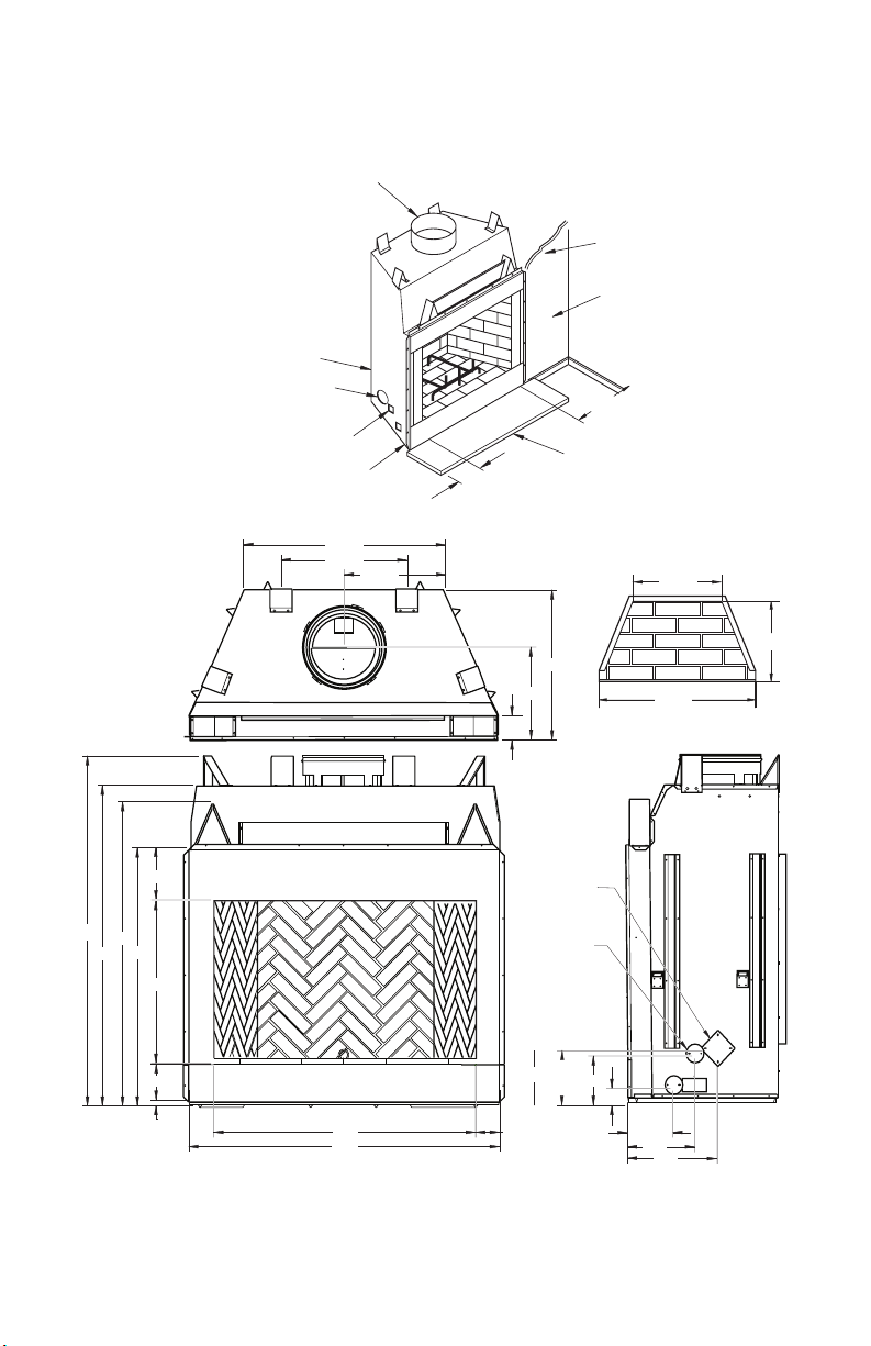
SPECIFICATIONS
42" MODELS
OUTSIDE AIR
11/2" AIR SPACE
BACK AND SIDES
0" TO
BOTTOM
GAS LINE
KNOCKOUTS
12" EACH SIDE
COMBUSTIBLE
WALL BOARD
NO COMBUSTIBLE
MATERIAL ON FACE
MINIMUM 18" TO
PERPENDICULAR
SIDEWALL
HEARTH EXTENSION
66" X 20"
2" CHIMNEY AIRSPACE
CLEARANCE TO
COMBUSTIBLE MATERIAL
42"
23 1/2"
25 1/8"
22 3/4"
30 1/2"
29"
4 3/8"
15 3/4"
5/8"
17 5/8"
67"
61"
49"
7"
1"
30"
11"
58"
42"
51 1/8"
4 1/2"
3 1/2"
9 1/2"
10 1/2"
81/2"
13"
17"
OUTSIDE
AIR
ACCESS
GAS LINE
ACCESS
42" HEARTH
Figure 1 - 42" Models (V)GCAT42(H)A AND (V)JCAT42(H,S) Series
www.fmiproducts.com 125655-01B4
SPECIFICATIONS Continued
50" MODELS
Figure 2 - 50" Models (V)GCAT50(H)A AND (V)JCAT50(H,S) Series
50"
23 1/4"
33 1/8"
2" CHIMNEY AIRSPA CE
CLEARANCE TO
COMBUSTIBLE MATERIAL
COMBUSTIBLE
WALL BOARD
NO COMBUSTIBLE
MATERIAL ON FACE
0" TO
BOTTOM
OUTSIDE AIR
11/2" AIR SPACE
BACK AND SIDES
GAS LINE
KNOCKOUTS
12" EACH SIDE
MINIMUM 18" TO
PERPENDICULAR
SIDEWALL
HEARTH EXTENSION
74" X 20"
38 1/2"
28 1/2"
43/8"
17 5/8"
19 1/4"
24"
49"
30"
11"
61"
67" 58"
7"
1"
59"
50" 4 1/2"
3 1/2"
9 1/2"
10 1/2"
8 1/2"
13"
17"
GAS LINE
ACCESS
OUTSIDE
AIR
ACCESS
50" HEARTH

www.fmiproducts.com
125655-01B 5
FIREPLACE INSTALLATION
FRAMING
1. Frameopeningforreplaceusingdimen-
sionsshowninFigures3and4.
2. If replace is to be installed directly on
carpeting, tile (other than ceramic) or any
combustible material other than wood
ooring,replacemustbeinstalledupon
a metal or wood panel extending full width
anddepthofreplace.
3. Setreplacedirectlyinfrontofthisopen-
ingandslideunitbackuntilnailinganges
touch side framing.
4. Checklevelofthereplaceandshimwith
sheet metal if necessary.
5. Before securing fireplace to prepared
framing, ember protector (provided) must
be placed between hearth extension (not
supplied) and under bottom front edge of
replacetoprotectagainstglowingembers
fallingthrough.Ifreplaceistobeinstalled
on a raised platform, a Z-type ember pro-
tector (not supplied) must be fabricated to
t your required platform height. Ember
protectorshouldextendunderreplacea
minimum of 1 1/2".Emberprotectorshould
be made of galvanized sheet metal (28
gauge minimum to prevent corrosion.
6. Usingscrewsornails,securereplaceto
framingthroughangeslocatedonsides
ofreplace.
Figure 3 - Framing Dimensions
Figure 4 - Corner Installation
SELECTING LOCATION
To determine the safest and most efcient
locationforthereplace,youmusttakeinto
consideration the following guidelines:
1. Thelocationmustallowforproperclear-
ances(seeFigures5and6).
2. Consider a location where replace will
not be affected by drafts, air conditioning
ducts, windows or doors.
3. A location that avoids cutting of joists or
roof rafters will make installation easier.
4. An outside air kit is available with this
replace(seeOptional Outside Air Kit on
page 7).
MINIMUM CLEARANCE TO
COMBUSTIBLES
Backandsidesofreplace 11/2" min.*
Frontofreplace 48"min.
Floor** 0"min.
Perpendicularwalltoopening 18"min.
Topspacers 0"min.
Mantelclearances
see Mantels, page 7
Chimneyouterpipesurface 2"min.
*Notrequiredatnailinganges
**Seestep2ofFraming
WARNING: Do not pack re-
quired air spaces with insulation
or other materials.
Minimum/Maximum Chimney Height for
Residential Installation
Minimumheightofchimney,measuredfrom
baseofreplacetouegasoutletoftermina-
tion,is16feetforstraightueorauewith
oneelbowset.Maximumdistancebetween
elbowsis6feet.Forsystemswithtwoelbow
sets, minimum height is 22 feet. Maximum
heightofanysystemis50feet.Thismeasure-
mentincludesreplace,chimneysectionsand
height of termination assembly at level of the
uegasoutlet(seeFigure16,page10).
Minimum/Maximum Chimney Height for
Outdoor Installation
Minimumheightofchimney,measuredfrom
baseofreplacetouegasoutletoftermina-
tion, is 9.5 feet (minimum of 4 feet of chimney
pipe sections required for outdoor installation).
71" (50" Models)
100" (50" Models)
65" (42" Models)
92" (42" Models)
86.5" (36" Models)
61" (36" Models)
Maintain 1 1/2"
Clearance
at Sides and
Back of Fireplace
1 1/2" Clearance
Not Required at
Nailing Flanges
30.125"
59" (50" Models)
58.125"
67.125"
51.25" (42" Models)
45.25" (36" Models)
28.250" (36" Models)

www.fmiproducts.com 125655-01B6
Note: For outdoor installations, fireplace
enclosure must allow for adequate drainage
and fresh air ventilation. It is recommended
that a sealed, corrosion resistant catch pan
with provision for drainage be installed under
replace within replace enclosure.
HEARTH EXTENSION
A hearth extension projecting a minimum of
20" in front of and a minimum of 12" beyond
eachsideofreplaceopeningisrequiredto
protectcombustibleoorconstructioninfront
of replace. Fabricate a hearth extension
using a material which meets the following
specications: a layer of noncombustible,
inorganic material having a thermal conduc-
tivityofK=0.84BTUIN/FT,HR.F(orless)at
1"thick.Forexample,ifthematerialselected
hasaKfactorof0.25,suchasglassber,the
following formula would apply:
0.25 x 1.0" = 0.30" thickness required
0.84
Thermalconductivity"K"ofmaterialscanbe
obtained from manufacturer or supplier of
noncombustiblematerial.Ifhearthextension
is to be covered, use noncombustible mate-
rial such as tile, slate, brick, concrete, metal,
glass,marble,stone, etc. Providea means
to prevent hearth extension from shifting and
sealgapbetweenreplaceframeandhearth
extension with a noncombustible material
(seeFigure5).
WARNING: Hearth extension
is to be installed only as shown
in Figure 4.
FIREPLACE INSTALLATION
Continued
Figure 5 - Hearth Extension
SealGap
FireplaceFront
EmberProtector
FireplaceFront
RaisedHearth
FireplaceFront
Elevated
EmberProtector
EmberProtector
SealGap
Hearth
Extension
MANTELS
Amantelmaybeinstalledifdesired(seeFigure
6). Woodwork such as wood trims, mantels
or any other combustible material projecting
from front face must not be placed within 18"
of replace opening. Combustible materials
above 18" and projecting more than 1 1/2" from
replacemustnotbeplacedlessthan21"from
the top opening of the replace (NFPA STD
211,Sec.7-3.3.3).
Mantels or any other combustible material
also may come up to side edge of black metal
faceofreplaceaslongasprojectionsfrom
frontfacefallwithinlimitshowninFigure6.
Figure 6 - Mantel Clearances to
Combustible Material
12 1/4"Ref.
6"
Ref.
21"Min.
18"Min.
11/2"Max.
3" Nom.
33°
Combustible
Material
Safe
Zone for
Projectionof
Combustible
Materials
FireplaceOpening
Upper
Sectionof
Fireplace
FIREBOX
SAFE ZONE
TopViewofFireplace
3"Max.
4.5"
18"Min.to
Perpendicular
SideWall
11.5"
33° Combustible
MaterialMust
NotOverlap
FrontFace

www.fmiproducts.com
125655-01B 7
Figure 8 - Lineal Gain
LINEAL GAIN
PART NO. DESCRIPTION GAIN
Georgian Fireplace 66 1/2
"
12-12DM
12-12HT PipeSection 10 5/8
"
18-12DM
18-12HT PipeSection 16 5/8
"
24-12DM
24-12HT PipeSection 23 5/8
"
36-12DM
36-12HT PipeSection 34 5/8
"
48-12DM
48-12HT PipeSection 46 5/8
"
RLT-12D
RLT-12HT RoundTermination 7 3/4
"
*
STL-12D SquareChase-Top
withSlipSection 7
"
to 15
"
*
*Thelinealgainfortheterminationsismea-
suredtotheuegasoutletheight.
Hemmed
End
12 3/8"
Stainless
InnerPipe
15"Galvanized
OuterPipe
ASSEMBLY AND INSTALLATION OF
DOUBLE WALL CHIMNEY SYSTEM
Eachdoublewallchimneysectionconsistsofa
galvanizedouterpipe,astainlesssteelinnerue
pipeandawirespacer.Thepipesectionsmust
be assembled independently as the chimney is
installed. When connecting chimney directly to
thereplace,theinneruepipesectionmust
beinstalled rstwith thelanced sideup.The
outer pipe section can then be installed over
5the uepipe sectionwith thehemmed end
up.Pressdownoneachpipesectionuntilthe
lancessecurelyengagethehemonthereplace
starter.Thewirewillassuretheproperspacing
between the inner and outer pipe sections.
Figure 7 - Outside Air Kit
SecuretoCollarswithMetalTape,
ScrewsorStraps(Min.of1/4"x20"
in size)
AirInlet
Location
MustAllow
ForBushes
orSnow
VentHood
Requiredfor
WallInstallation
AirInlet
Eyebrow
VentedCrawlSpace
(CheckLocalCodes
BeforeInstallingina
VentedCrawlSpace)
CHIMNEY PIPE
TheFMIPRODUCTS,LLCchimneysystem
consists of 12", 18", 24", 36" and 48" snap-
lock, double-wall pipe segments, planned
for maximum adaptability to individual site
requirements. Actual lengths gained after
ttingoverlapsmustbetakenintoconsider-
ation (lineal gain) and are given in the lineal
gainchart(seeFigure8).LinealGainisthe
actual measurable length of a part after two or
morepartsareconnected.ForCanada,use
chimneypartsdesignated"HT".
VENTING INSTALLATION
OPTIONAL OUTSIDE AIR KIT
(MODEL AK4/AK4F)
The installation of an outside air kit should
be performed during the rough framing of
thereplaceduetothenatureofit'slocation.
Outsidecombustionairisaccessedthrough
a vented crawl space (AK4F) or through a
sidewall (AK4).
CAUTION: Combustion air
inlet ducts shall not terminate
in attic space.
The maximum height for the
air vent can not exceed 3 feet
below the ue gas outlet of the
termination.
WARNING: The opening in
the collar around the chimney at
the top of the replace must not
be obstructed. Never use blown
insulation to ll the chimney
enclosure.

www.fmiproducts.com 125655-01B8
VENTING INSTALLATION
Continued
OFFSET
RISE CHIMNEY LENGTH
A B 12" 18" 24" 36" 48"
4 3/8" 16 3/8"
ELBOWSETONLY
9 3/4" 25 1/2"
1
12 3/4" 30 3/4"
1
15" 34 3/4"
1
18" 40"
1 1
21 1/4" 46 1/4"
1
23 3/4" 49 1/4"
1 1
27 3/4" 56 3/4"
1
30" 60 3/4"
1 1
33" 66"
1
36" 71"
1 1
38 1/4" 75"
2
41 1/4" 80 1/4"
1 1 1
45" 86 3/4"
2
46 3/4" 89 1/2"
1 1 1
51" 97"
1 1
53 1/4" 101"
2
56 1/4" 106 1/4"
2
59 1/4"111 1/2"
1 1 1
61 3/4" 115 1/2"
1 2
64 3/4" 120 3/4"
1 2
68 1/4" 127"
2 1
70" 130"
1 1 2
74 1/4" 137 1/2"
1 2 1
76 3/4" 141 1/2"
1 2 1
79 3/4" 146 3/4"
4
OFFSET CHART (22-50 FT. SYSTEM HEIGHT)
Figure 10 - Ceiling Support Pipe
12S-12DM
2"Min.
Straps
Straps
Straps
Straps
DetailA
ReturnElbow
DetailB
AngleFirestop
SeeDetailA
SeeDetailB
Continue to assemble chimney sections as
outlined above, making sure that both the
inner and outer pipe sections are locked to-
gether. When installing double wall snap-lock
chimney together, it is important to assure
the joint between the chimney sections is
locked. Check by pulling chimney upward
afterlocking.Thechimneywillnotcomeapart
Figure 9 - Elbow Offset
B
A
Screws
ifproperlylocked.Itisnotnecessarytoadd
screws to keep the chimney together (excep-
tion,seeFigure9).
USING ELBOW OFFSETS (30E-12DM)
1.
Toachievedesiredoffset,youmayinstall
combinations of 12", 18", 24", 36" and 48"
length of double wall pipe (see offset chart
andFigure9).
2.
Chimney weight above offset rests on
return elbow. Straps must be securely
nailedtoraftersorjoists(seeFigure10,
details A and B).
3. Maximum length of pipe between sup-
ports(return elbowor12S-12DM)is6'
ofanglerun. Maximumoftwo 6'angle
run sections per chimney system (see
Figure11,page9).
4. All pipe connections between the offset
and return must be secured with two
screws on the outer pipe only (see
Figure 9). Do not penetrate the inner
stainless.

www.fmiproducts.com
125655-01B 9
VENTING INSTALLATION
Continued
FIRESTOP SPACERS (FS-10)
Firestop spacers are required at each point
where the chimney penetrates a oor space.
Their purpose is to establish and maintain
the required clearance between the chimney
and the combustible materials. When the pipe
passes through a framed opening into a living
spaceabove,therestopmustbeplacedonto
theceilingfrombelowasshowninFigure12.
They also provide complete separation from
one oor space to another or attic space as
required by most codes. When the double wall
pipe passes through a framed opening into an
atticspace,therestopmustbeplacedintoan
atticoorasshowninFigure13.
Figure 12 - Firestop Spacer with Living
Space Above Ceiling
Figure 13 - Firestop Spacer with Attic
Space Above Ceiling
Existing
Ceiling
Frame
Firestop
Spacer
Screwsor
Staples
(Min.of8)
Firestop
Spacer
ScrewsorStaples
(Min.of8)
PENETRATING ROOF
Tomaintaina2"clearancetothepipeona
roof with a pitch, a rectangular opening must
be cut.
1. Determinecenterpointthroughwhichpipe
will penetrate roof.
2. Determine center point of roof. Pitch is
distance the roof drops over a given span,
usually 12". A 6/12 pitch means that roof
drops 6" for each 12" measured horizon-
tally down from roof rafters.
3. Useroofopeningchart(Figure14,page
10) to determine correct opening length
andashingrequired.
4. Removeshingles around openingmea-
sured.Cutoutthissection.
Existing
Ceiling
Frame
Figure 11 - Typical Offset Terminations
Return
Elbow
Offset
Elbow
Return
Elbow
Offset
Elbow
6'Max.
6'Max.
6'Max.
6'Max.
6'Max.
6'Max.
Return
Elbow
Offset
Elbow
Offset
Elbow
Return
Elbow
A B C
Offset
Elbow
Ceiling
SupportPipe
12S-12DM
Return
Elbow

www.fmiproducts.com 125655-01B10
VENTING INSTALLATION
Continued
Pitch Slope Opening
"A" Max.
Used Flashing
Model No.
Flat 0° 19.5" V6F-10DM
0-6/12 26.6° 22' V6F-10DM
6/12-12/12 45.0° 27" V12F-10DM
5. Add next sections of pipe until end
penetrates roof line. Check to see that
properclearancesaremaintained.Extend
chimney by adding sections of double wall
pipe until pipe is minimum of 30" above
highestpointofroofcutout.Termination
and chimney must extend a minimum of
36" above highest point where it passes
through roof.
19.5" Min. 30" Min.
2" Min.
2" Min.
2" Min.
Opening "A"
Figure 14 - Roof Opening Measurements
NailOnly
Outer
Perimeter
ofFlashing
StormCollar
Flashing
Cone
UnderlapShingles
at Bottom
Overlap
ShinglesTop
andSidesOnly
Figure 15 - Flashing Installation
FLASHING INSTALLATION (V6F-10DM
OR V12F-10DM)
Determine the ashing to be used with the
roofopening chart.Slide ashingover pipe
until base is at against roof. Replace as
many shingles as needed to cover exposed
areaandashingbase.Secureinpositionby
nailingthroughshingles(seeFigure15).DO
NOTNAILTHROUGHFLASHINGCONE.
Storm Collar Installation (SC2-1)
Placestormcollaroverpipeandslidedown
until it is snug against the open edge of the
ashing (see Figure 16).Apply waterproof
caulk around the perimeter of the collar to
provide a proper seal.
Figure 16 - Storm Collar
Chimney
Pipe
Waterproof
Caulk
Storm
Collar Flashing
Installing Flashing on a Metal Roof
Wheninstallingtheashingonametalroof,
it is required that putty tape be used between
theashingandtheroof.Theashingmustbe
secured to the roof using #8 x 3/4" screws and
then sealed with roof coating to prevent leak-
age through the screw holes. A roof coating
must also be applied around the perimeter of
theashingtoprovideaproperseal.

www.fmiproducts.com
125655-01B 11
VENTING INSTALLATION
Continued
10 FOOT RULE
Alluegasoutletchimneyterminationsmust
extend a minimum of 3 feet in height above
the highest point where it passes through
the roof and must be at least 2 feet above
the highest point of the roof that is within a
horizontaldistanceof10feet(seeFigure19).
FINISHING FIREPLACE
Combustible materials, such as wallboard,
gypsum board, sheet rock, drywall, plywood,
etc. may make direct contact with sides and top
aroundthereplaceface.Itisimportantthat
combustible materials do not overlap the face
itself. Brick, glass, tile or other noncombustible
materials may overlap the front face provided
they do not obstruct essential openings like
louvered slots or any other opening. When
overlapping with a noncombustible facing
material, use only noncombustible mortar or
adhesive.
24"Min.
24"Min.
18"
Min.
Typ.
Figure 18 - Multiple Chase Installation
10'
2'Min.
10'
3'Min.
2'Min. 3'Min.
Levelof
FlueGas
Outlet
Figure 19 - 18 Foot Rule
Terminations/Spark Arrestor
Thereplacesystemmustbeterminatedwith
thelistedroundtoporchaseterminations.In
any case, refer to the installation instructions
supplied with the termination.
CAUTION: Do not seal open-
ings on the rooftop ashing. Fol-
low the installation instructions
provided with the termination
being used.
RTL-12D
Levelof
FlueGas
Outlet
Stainless
InnerFlue
Pipe
Waterproof
Caulking
Storm
Collar
Flashing
Underlap
Shingles
Figure 17 - Termination
Overlap
Shingles(Top
andSidesof
FlashingBase)
CHASE INSTALLATIONS
Instructions for chase installations are
included with the chase style termination
chosen. In a multiple chase installation, be
sure to provide adequate distance between
terminations to prevent smoke spillage from
one termination to another. We suggest that
terminations be separated at least 24", center
to center and stacked at a vertical height dif-
ferenceof18"(seeFigure18).
Note: If a decorative shroud is to be installed,
contact the manufacturer for specications.
Secure
Termination
toOuter
Pipewith3
Screws

www.fmiproducts.com 125655-01B12
REFRACTORY PANEL INSTALLATION
IMPORTANT: Installation of brick
should be done after the re-
place is placed in a permanent
location.
1. Removegrate,screenassembliesandall
hardwarecomponentsoutoftherebox.
Thebottom panel ispre-installed in the
rebox.Makesurethebottomrefractory
panelsiscenteredinthereboxandush
withthefrontofthereplace.
2. Placecardboardontopofbottomrefrac-
tory panel as a protection to prevent ship-
ping and scratching during installation of
the other panels.
3. Position"Z"shapedgrateretainingbrack-
ets on top of the notched area toward the
rearofthebottomrefractory.Theyshould
be positioned a distance apart as shown
inFigure20.
4. Install rear refractory panel. This panel
hasatopandbottom.Todeterminewhich
is which, match up the pattern on the rear
panel with the left and right sides before
Figure 21 - Installing Refractory Panels
LEFT BRICK
PANEL
PANEL
RIGHT BRICK
REAR BRICK
PANEL
BOTTOM
BRICK PANEL
GRATE GRATE RETAINER
ASH PANEL
BRACKET (2x)
UPPER CORNER
BRACKET (2x)
Figure 20 - Installing Grate Retainers
installingtherearpanel.Makesurepanel
is center before continuing.
5. Installtherightandleftrefractorypanels
with the gas line knockouts orientated
down toward the bottom refractory. Align
the left and right panels with the rear panel
so the grout lines line up.
6. Install the upper corner brackets and
tightensetscrews(Figure21).
7. Installgratebyplacingrearlegsintoslots
inthegrateretainers(Figure21).

www.fmiproducts.com
125655-01B 13
WARNING: Risk of re! Re-
place grate with FMI PRODUCTS,
LLC grate only (see Parts, page
20). This grate has been de-
signed to keep the operation of
your replace safe and efcient.
INSTALLING SCREEN
1. Slideroundendofscreenrodintoringsat
top of screen. Attach one push-on nut to end
of rod before attaching last ring of screen.
2. Inserttheroundendscreenrodintohole
on the left and right side of smoke shelf
(Figure22).
REFRACTORY PANEL INSTALLATION
Continued
Gas line hook up should be done by your
supplieroraqualiedserviceperson.
Note: Before you proceed, make sure your
gas supply is turned off.
Useonlya1/2"blackironpipeandappropri-
atettings.
1. Removeknockoutindentationonrefrac-
toryorrebrickwalllocatedaboverefrac-
tory hearth oor. Knockout indentation
mustbermlytappedwithanysolidobject
such as a 1/2" dowel until it is released.
Removefragmentedportionsofrefractory
(seeFigure23).
2. Remove gas line cover plate located on
eithersideofreplaceandpulloutinsula-
tion from gas line conduit sleeve. Save
insulationforreuse.Replacescrews.
3. Runa1/2"blackirongaslineintoreplace
through the rear at gas line conduit sleeve (if
usingaraisedplatform,addheight).Provide
sufcientgaslineintoreplacechamberfor
ttingconnection(seeFigure24).
Note: Secure incoming gas line to wood
framing to provide rigidity for threaded end.
4. Repackinsulationaroundgaslineandinto
sleeveopening.Seal any gapsbetween
gas line and refractory knockout hole with
refractory cement or commercial furnace
cement,Installthegasapplianceorcap-off
gas line if desired.
Figure 23 - Gas Line Access
Side
Firebrick
Finished
Side
Brick with
Access
Hole
Outsideof
Fireplace
GasLine
Conduit
Insulation
Gas
Conduit
Cover
1/2"Dowel
Seal
Opening
with
Refractory
Cement
Outsideof
Fireplace
GasLine
Conduit
Repack
Insulation
Incoming
1/2" Black
IronPipe
Side
Firebrick
Finished
Side
ProvideEnough
Threaded
EndforFitting
Connection
Figure 24 - Gas Line Installation
Remove
Knockout
Rating
Plate
HoleforScreen
Rod
Leading
Bricks
Figure 22 - Installing Fireplace Screen
3. Mountatendofscreenrodwith#10x5/8"
to center of smoke shelf.
4. Installotherscreenrodinsamemanner.
OPTIONAL GAS LINE INSTALLATION

www.fmiproducts.com 125655-01B14
CAUTION: All gas piping
and connections must be tested
for leaks after the installation
is completed. After ensuring
that the gas valve is on, apply
soap and water solution to all
connections and joints. Bubbles
forming show a leak. Correct
all leaks at once. DO NOT USE
AN OPEN FLAME FOR LEAK
TESTING AND DO NOT OPER-
ATE ANY APPLIANCE IF A LEAK
IS DETECTED. LEAK TESTING
SHOULD BE DONE BY A QUALI-
FIED SERVICE PERSON.
WARNING: Do not operate an
unvented gas log set in this re-
place with the chimney removed.
A gas line or gas log lighter may be installed
for the purpose of installing a vented or vent-
free decorative gas appliance incorporating an
automatic shutoff device and complying with
theStandard for Decorative Gas Appliances for
Installation in Vented Fireplaces, ANSI Z21.60
or American Gas Association draft requirements
for Gas Fired Log Lighters for Wood Burning
Fireplaces, Draft NO. 4 dated August, 1993.
OPTIONAL GAS LINE INSTALLATION
Continued
If you install a decorative gas appliance
(vented gas log), the decorative gas appliance
must comply with the Standard for Decorative
Gas Appliance for Installation in Solid Fuel
Burning Fireplaces, ANS Z21.60 or Z21.84
and shall also be installed in accordance with
the National Fuel Gas Code, ANSI 7223NFPA
54 latest edition.
Ifyouwishtoinstallanunvented(vent-free)
gas log set, only unvented gas log sets which
have been found to comply with the standard
forunventedroomheaters,ANSIZ21.11.2are
tobeinstalledinthisreplace.
WARNING: If the replace
has been used for wood burning,
the rebox and chimney must be
cleaned of soot, creosote and
ashes be a qualied chimney
cleaner. Creosote will ignite if
heavily heated.
WARNING: When using a
decorative vented gas log, the
damper must be removed or
permanently locked in the fully
openposition andthe glassdoors
must be in the fully open position.
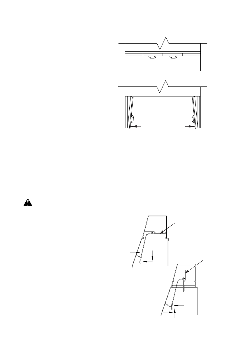
PUREFIRE HOOD INSTALLATION
1. ThePureFirehoodsuppliedwiththisre-
place is packaged in a separate box and
placedinthereboxduringshipping.
2. Removehoodfrombox.Locatebrackets
(quantity 2) and screws (quantity 4) for
hood installation in the hardware bag.
3. Usingscrewsprovided,securethebracket
totheinnerdomeofthereplaceasshown
inFigure25.Theleftandrightbracketare
different.Theedgethatisstraightwillbe
closertothereplaceopening.
4. Lifthoodupintothereplaceandplaceit
ontheretainingbrackets(Figure25).The
rear of the hood will touching the rear of
thereplace. Figure 25 - Installing PureFire Hood
www.fmiproducts.com
125655-01B 15
Figure 27 - Installing Bottom Door Frame
and Air Deectors
Bottom
DoorRail
Ash Box
Center
Brick
Air
Deector
Ring
Handle Screws
DOOR ADJUSTMENT
Removedoorsandslightlyloosenlowerpivot
clipsandupperspringclips.Replacedoors
and fully close them. Use 1/8" shims (any
material)toleveldoors.Oncepropersetting
is achieved, carefully open doors enough so
thatyoucanaccessspringclipswithaPhillips
screwdriver.Tightenscrews.SeeFigure29.
Figure 28 - Installing Bi-Fold Doors
Spring
Clip
InsertPin
intoSpring
Clip
Pivot
Hole
Insert
Bottom
PivotPin
intoHole
FoldDoor
andSlide
TopPins
IntoTrack
Figure 29 - Adjusting Bi-Fold Doors
INSTALLING GLASS DOORS
Spring clips have been installed but some
adjustmentsmaybeneeded.Ifdoorsdonot
close properly or do not appear straight, see
Door Adjustment.
1. With bi-fold doors completely folded,
insert bottom pivot pin into pivot hole
located near bottom corner of front face
opening and swing door to vertical posi-
tion making sure top pins slide into door
track.Doorisinstalledwhentopdoorpin
snaps into spring clip.
2. Repeatstep1forremainingdoor.
Ifyounddoorsdonotcloseproperlyordo
not appear level or straight, proceed with
section on door adjustment,
Spring
Clip
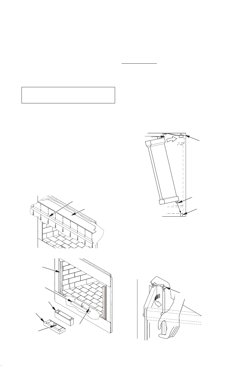
AIR DEFLECTOR AND GLASS DOOR INSTALLATION
IMPORTANT: Install glass door
frame before installing glass door.
INSTALLING DOOR FRAMES
1. Remove screws from smoke shelf (see
Figure26).
2. Mount top door frame and secure with
screws removed in step 1.
3. Removecenterashrefractorybypulling
ringhandle(seeFigure27).
4. Removeashbox.
5. Removethreescrewslocatedatfrontof
rebox(seeFigure27).
6. Align bottom rail mounting holes with
holesatfrontofreboxandsecurewith
screws removed in step 5.
7. Placeash boxinplace.Replacecenter
ash refractory.
Figure 26 - Installing Top Door Frame
TopDoorFrame
SmokeShelf
INSTALLING AIR DEFLECTORS (42''
MODELS ONLY)
Slideairdeectorinbetween thefrontside
face and side brick panel (see Figure 27).
The notched end of the deflector sits on
bottomhearth.Airdeectordoesnotrequire
any fastening.
Thefrontsidefacesandsidebrickpanelswill
holdthedeectorinplace(seeFigure27).
www.fmiproducts.com 125655-01B16
Figure 30 - Bi-Fold Glass Doors
DoorsFullyClosed
FireplaceFront
Doors
FullyOpened
FireplaceFront
OPERATION AND MAINTENANCE GUIDELINES
Figure 31 - Operating Damper Handle
Damper
Weight
ToClose
Damper
ToOpen
Damper
Damper
Weight
OUTSIDE AIR AND DAMPER
HANDLE OPERATION
Thedamperhandle,whichopensandcloses
the damper blade, is located in the upper front
faceofthereplace.Pushingthehandlefor-
ward and up through the keyway slot will free
damperbladetoautomaticallyopen.Pushing
the handle forward and down will lock damper
bladeclosed(seeFigure31).
GLASS DOORS
Glass doors are optional with the replace.
Whenreplaceisinoperation,doorsmustbe
fullyopenedorfullyclosedpositiononlyorare
hazardmaybecreated(seeFigure30).
Areplaceequippedwithglassdoorsoperates
muchdifferentlythanareplacewithanopen
front.Areplacewithglassdoorshasalimited
amount of air for combustion.
Excessiveheatwithinthereplacecanresultif
toolargeareisbuiltorifcombustionairgate
isnotcompletelyopen.Thefollowingtipsshould
be followed to assure that both the replace
and glass door retain their beauty and function
properly.Boththeuedamperandglassdoors
mustbefullyopenedbeforestartingre.Thiswill
providesufcientcombustionairandmaintain
safetemperaturesinrebox.
IMPORTANT: The glass must be allowedto
warmslowlyandevenly.Thetemperedglasswill
withstandagradualtemperatureriseto550°F,
whichismorethananormalrewillgenerate.
Suchmaterialsaspitch/waxladenlogs,verydry
mill end lumber and large amounts of paper or
cardboard boxes can create an excessively hot
reandshouldnotbeburnedinthisreplace.
Alwayskeeptherewellbackfromthedoors
andneverallowamestocontacttheglass.
WARNING: Fireplaces
equipped with glass doors
should be operated only with
doors fully opened or doors fully
closed. Doors, if left partly open,
may draw gas and ame out of
the replace opening creating
risks of both re and smoke.
Cleaning Glass
Cleanglasswithanycommercialglasscleaner
or soap and water. Do not use any abrasive
materialtocleanglass.Donotcleanglasswith
anycoolwaterifglassisstillhotfromthere
and smoke.

www.fmiproducts.com
125655-01B 17
PUREFIRE EMISSION CONTROL SYSTEM
This replace is equipped with a PureFire
Emission Control System. The Catalytic
Hoodsystemreducesparticulatesemissions
inawoodburningreplacetomeettheEPA
Wood-Burning Fireplace Program Phase 2
emission level.
TheEPAqualifyinglabel,shownonpage18,
willbeafxedtothecatalyst.Beforelighting
therstre,removeandmaintainthislabelin
a safe place if needed for permits or building
inspection.Priortobeginninginstallation,con-
tactyourlocalbuildingofcialtodeterminethe
needtoobtainapermit.Forproperoperation,
catalyst must be replace every 3 to 5 years.
FUELING GUIDELINES
Thereplacegratemustalwaysbesecured
totheretainingbracketsprovided.Theposi-
tion of the grate must be centered against the
backwalloftherebox.
Burn only dry, seasoned (cured) wood with
less than 20% moisture. Avoid the use of
treated, painted and laminated wood. Never
burngarbageorotherforeignmaterials.Do
notusearticiallogs,colorednewspaperor
petroleumbasedrestarters.Avoidwoodwith
high salt content. All of these materials may
contain compounds which can shorten the
life of the catalyst. Wet or unseasoned wood
may lower catalytic temperatures and result
ininefcientoperation.
Thecatalystisdesignedtofunctionatopti-
mumefciencywhenthereplaceisburning
clean, dry, cord wood as replace fuel.A
simple visual inspection of the chimney dur-
ing the wood burning process will determine
catalyst performance.
The fuel load should always be placed on
thebackofthegrate. Usecleandry wood,
seasoned cord wood is the best choice.
Never burn trash, plastics, gasoline, rubber,
industrialsolvents,ammableliquids,naptha,
household garbage, material treated with
petroleum products, leaves, paper products,
cardboard or salt driftwood.
RefertoyourFMIPRODUCTS,LLCHome-
owner's Guide includedwithyourreplacefor
properrebuildingtechniqueandashremoval
procedures.Thesefuelingguidelinesmustbe
followed in order to achieve maximum emis-
sionsperformancefromthePureFireSystem.
OPERATION
Theproperuseofawoodburningreplace
equipped with the catalyst will signicantly
reducetheemissionsthatitproduces.Simple
fuel considerations with regard to moisture
content, size, and quality of fuel will help
control the production of wood smoke and
improve the performance of the catalyst and
replace efciency. With proper care, the
catalyst will provide years of fuel savings
and lowered emissions. By following some
simple guidelines, you will ensure maximum
performance and longevity.
Thesmokethatisusually seencomingout
of a chimney is essentially a combination of
unburned fuel (carbon and hydrogen) and
moistureintheformofwatervapor.Thecata-
lyst is a technology that provides secondary
combustion for the wood burning process.
MAINTENANCE
ThePureFireSystemisamaintenancefree
technology.Donotattempttoremoveorclean
thecombustor.Thedirectamefromthere
will clean the combustor. Only a certified
technicianshouldremovetheunit.Toensure
properreplaceoperation,thePureFireSys-
tem should be replaced every 3 to 5 years
(see Parts on page 20).
NOTE:Chimneysmokemaybevisibleduring
therst8to10minutesofreplaceoperation
whenthereisrstgettingstartedandthe
nal8to10minutesofoperationwhilethere
isdissipating.Undernormaloperatingcondi-
tions, you should see little or no smoke coming
out of the chimney. If continuous smoke is
visible, make sure only dry seasoned wood
isbeingburned.Ifvisiblesmokecontinues,
the combustor has ceased to function or there
isthermalcrumbling.CallFMIPRODUCTS,
LLCat1-866-328-4537forreplacementparts.

www.fmiproducts.com 125655-01B18
PUREFIRE EMISSION CONTROL SYSTEM
Continued
WARRANTY
FMIPRODUCTS,LLCwarrantyobligations
for the PureFire Emissions Control System
are limited to the terms set forth below.
FMI PRODUCTS, LLC warrants to the
consumer who purchases a new solid fuel
burningreplacecontainingaPureFireEmis-
sionsControlSystemasanewcomponent,
to replace the catalyst at no charge should
it cease to function within three years from
thedateofpurchase.ThePureFireCatalytic
Componentisdesignedtoperformefciently
forthreeyearsofreplaceoperation.ONLY
recommendedfuelsshouldbeburned.Fol-
low the fueling directions in manufacturers
operation manual. For warranty purposes,
proof of fireplace purchases is required.
Labor for removal and/or installation of the
catalytic component is not the responsibility
of the manufacturer.
NeitherFMIPRODUCTS,LLCnorthedealer
who sells the PureFire Emissions Control
Systemisresponsibleforindirect,incidental,
special, punitive or consequential damages
arising out of the improper use of this product
or the continued use of this product beyond
the required replacement period.
MANUFACTURER: FMI Products, LLC
MODEL NO: GCAT50 & VGCAT50
PARTICLE EMISSIONS: 4.4 GRAMS/KG OF WOOD BURNED
FIREPLACE
SMOKE EMISSIONS RANGE
Higher Emissions
Lower Emissions
012.0
THIS MODEL
EPA PHASE 2 EMISSIONS LEVEL
4.4 5.1
Better Worse
U.S. Environmental Protection Agency
Wood-burning Fireplace Program
Phase 2 Qualified models are cleaner and pollute less than those models that
have not met this emissions level. Exposure to smoke has been associated with
respiratory illness and other health problems. Models that have lower smoke
emissions may reduce your risk.
PHASE 2 QUALIFIED
For more information go to www.epa.gov/burnwise
Fireplaces with lower emissions produce less smoke when installed and operated properly.
* EPA has determined, based on testing by an accredited independent laboratory and a certification
of conformity by a nationally recognized certification body, that this model qualifies at the Phase 2
emissions level for U.S. EPA's Voluntary Fireplace Program.
For proper operation, catalyst must be replaced every 3 to 5 years.
125574-02
MANUFACTURER: FMI Products, LLC
MODEL NO: GCAT42 & VGCAT42
PARTICLE EMISSIONS: 4.4 GRAMS/KG OF WOOD BURNED
FIREPLACE
SMOKE EMISSIONS RANGE
Higher Emissions
Lower Emissions
012.0
THIS MODEL
EPA PHASE 2 EMISSIONS LEVEL
4.4 5.1
Better Worse
U.S. Environmental Protection Agency
Wood-burning Fireplace Program
Phase 2 Qualified models are cleaner and pollute less than those models that
have not met this emissions level. Exposure to smoke has been associated with
respiratory illness and other health problems. Models that have lower smoke
emissions may reduce your risk.
PHASE 2 QUALIFIED
For more information go to www.epa.gov/burnwise
Fireplaces with lower emissions produce less smoke when installed and operated properly.
* EPA has determined, based on testing by an accredited independent laboratory and a certification
of conformity by a nationally recognized certification body, that this model qualifies at the Phase 2
emissions level for U.S. EPA's Voluntary Fireplace Program.
For proper operation, catalyst must be replaced every 3 to 5 years.
125574-07

www.fmiproducts.com
125655-01B 19
TECHNICAL SERVICE
You may have further questions about in-
stallation, operation, or troubleshooting.
If so, contact FMI PRODUCTS, LLC at
1-866-328-4537.
When calling please have your model and se-
rialnumbersofyourreplaceready.
Youcanalsovisitourwebsiteat
www.fmiproducts.com.
REPLACEMENT PARTS
If this product is missing a part or has a
broken component, please do not return it
to the store. Call FMI PRODUCTS, LLC at
1-866-328-4537 to answer questions and
replace parts under warranty.
Note: Use only original replacement parts.
This will protect your warranty coverage for
parts replaced under warranty.
When calling or writing, please have your
model and serial numbers of your replace
ready.
Modelandserialnumberinformationareinthe
replace'sratingplatelocatedonthereplace
smoke shelf.

www.fmiproducts.com 125655-01B20
PARTS
MODELS (V)GCAT42/50(H)A SERIES AND (V)JCAT42/50(H,S) SERIES
1
21
20
5
6
7
10
9
11
12
13
16/17
15
14
8
24
23
3
25
18
2
22
19
4
26
27
28
29
30
This manual suits for next models
9
Table of contents
Popular Other manuals by other brands


NextBase
NextBase Click Lite Instructions for installation and use

Evenheat
Evenheat Studio Pro 24 operating instructions

Wilo
Wilo Control SC-Fire Electric Installation and operating instructions

Nokia
Nokia Xpress-on user guide

StarTech.com
StarTech.com SDOCKU33HB instruction manual

BT
BT BT-CSIM-T user guide


