manuals.online logo
Brands
  1. Home
  2. •
  3. Brands
  4. •
  5. Evenheat
  6. •
  7. Other
  8. •
  9. Evenheat Studio Pro 24 User manual

Evenheat Studio Pro 24 User manual

Studio Pro 24
Installation and Operating Instructions
North American Model
Jan 2019
Page 1of 17
Your Studio Pro 24 has been shipped in 3 sections for easy placement. Narrow doorways and halls are possible to navigate with each of the 3, individual
sections. This allows you to place the kiln where it would be otherwise impossible or impractical to do with a kiln of this size.
SAFETY
Read and understand these installation instructions for safe and proper installation. Installation requires the lifting and moving of individual kiln sections.
Personnel capable of lifting and managing the moving process must be used. If you have any questions please contact Evenheat Kiln at 989-856-2281 or at
evenheat-kiln.com.
Kilns are as safe as any other electrical appliance when used under normal and proper operating conditions. To create and maintain this safe environment
observe all installation and safety precautions.
Warning Symbol Descriptions
Warning symbols are used throughout these installation instructions. These symbols alert the installation personnel to certain hazards and important
information. Pictured below are symbols used along with a description of each.
The Exclamation Point alerts you to particular cautions, hazards and information.
The Lightning Bolt alerts you to specific information regarding the risk of electric shock.
Electric shock may result in injury or death.
Emergency Shut Off Provision
The kilns power supply connection (plug/receptacle, breaker or disconnect) acts as the emergency electrical power shut off. Access to these
devises should be unobstructed and safe at all times.
All electrical installations for direct wired models (those without a plug/receptacle connection) must include a power disconnect near the kiln and that
is easily accessible and safe for emergency power shutoff.
Electrical Safety
A licensed electrician should be used for all electrical installation and service. All applicable local, state and federal electrical codes must be
followed.
Use correct voltage, wire size and fuse or breakers. Kiln electrical requirements are located on the kiln nameplate. Make sure all electrical connections
are tight. Avoid using aluminum wire.
Always use the proper electrical receptacle. Never alter the kiln cordset or cordset plug. Alterations can be dangerous. Alterations will void any
warranties along with nullifying any Listing Agency markings.
Evenheat recommends that a voltage check be performed before placing the kiln into service, ideally before actual purchase. Operating
voltage varies, with common operating voltages being 208V and 240V. The kilns operating voltage (printed on the kilns nameplate) must
match the applied voltage (actual electrical service voltage). If it does not, do not install or operate the kiln as potential electrical and fire
hazards exist. Contact Evenheat for guidance in such cases.
The kiln must be properly grounded.
Unplug or disconnect the kiln from the electrical service before accessing the chamber for servicing or vacuuming. Do not attempt to touch
or replace the heating elements while the kiln is plugged in or connected to the electrical service. Electric shock may result in serious injury
or death.
Never, ever use an extension cord to operate a kiln.
Studio Pro 24
Installation and Operating Instructions
North American Model
Jan 2019
Page 2of 17
Kiln Location Safety
The best location for the kiln is a concrete floor. If not available, the kiln must be placed on a minimum of 2” of masonry extending at least 12” beyond
the outside perimeter of the kiln.
Do not place or use kiln on combustible surface.
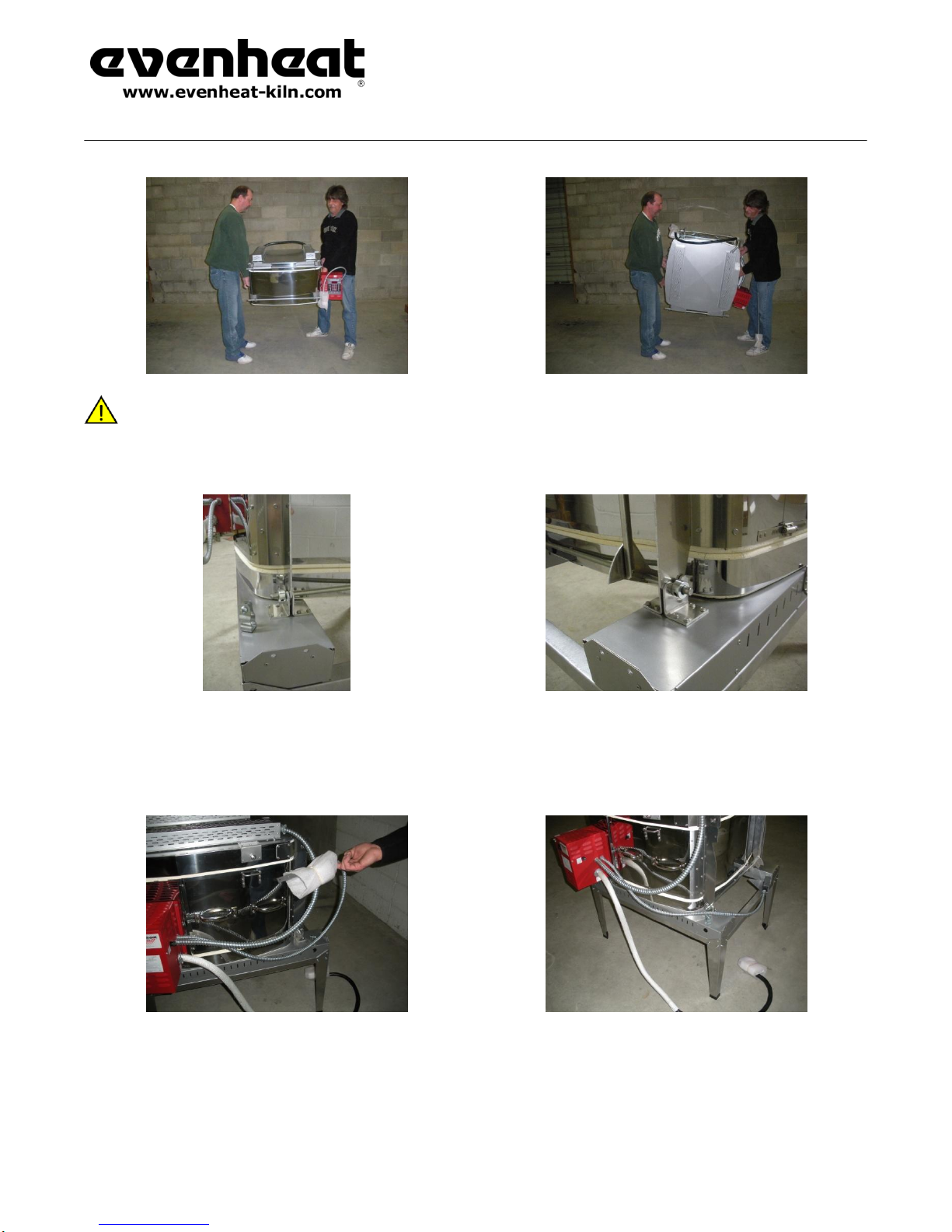
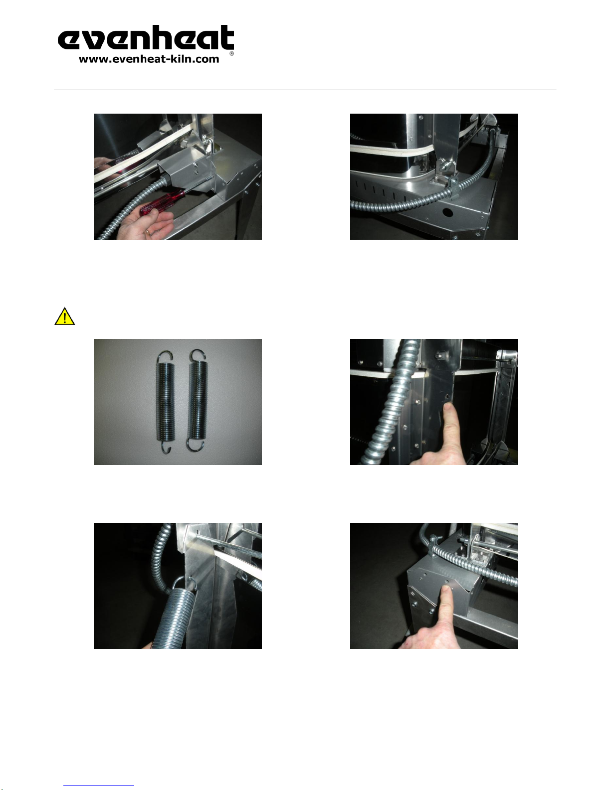
Place only on the metal stand provided by Evenheat Kiln, Inc.
The surface on which the kiln is placed shall be capable of safely supporting the combined weight of the kiln, kiln load and any operating personnel.
Observe all building, fire and safety codes when installing the kiln.
Do not install the kiln closer than 12” (31cm) from combustible wall surface or object or 36” from any ceiling surface in all opened and closed
positions.
Install in a covered, well ventilated area.
Never place the kiln in a small, enclosed area such as a closet, cabinet or very small room. The room in which the kiln is placed into service shall be
capable of safely dissipating all heat produced by the kiln.
Do not place the kiln in any structure resembling a carport or screened in porch. Avoid areas that are subject to outdoors weather.
Never install a kiln outside. Avoid moisture.
It is the user’s responsibility to be knowledgeable regarding any and all contaminants, produced by the ware during firing, and take steps to properly
and legally contain and dispose of these contaminants.
It is the user’s responsibility to provide ventilation capable of removing all gases, fumes and other airborne contaminants produced by the ware
during firing safely from work the area and building structure.
Do not store flammable or combustible products near or in the same room the kiln such as gasoline, paint, aerosol cans, paper, curtains,
plastics, etc. Better yet, store these items in another separate structure designed for this purpose.
Position the power supply cables, power supply conduit, controller cables, pyrometer thermocouple leads and other materials in such a way as not to
create a tripping hazard around the kiln.
The area around the kiln should be free of obstructions that interfere with the proper and safe operation of the kiln.
Never place anything under or above the kiln for storage. Absolutely nothing should be propped against the kiln.
Kiln Use Safety
The surface of the kiln is hot and burn injuries are possible. Keep all children and unsupervised personnel away. Always wear protective
clothing, gloves and eyewear when operating and handling a hot kiln.
Use extreme care when accessing a functioning and/or hot kiln. Your kiln is equipped with a power interrupt switch assembly that is
designed to remove electrical power from all heating elements when either the lid or chamber is opened. This power interrupt switch
assembly is a mechanical devise and it can fail. Under no circumstances should you touch the heating elements with your body or any other devises
like tools. Electrical shock may result in serious injury or death.
Use care when accessing or looking into a hot kiln, this includes looking through a cracked lid or peepholes. High heat escapes quickly and
burn injury may result. When accessing or looking into a hot kiln, approach slowly and wear protective clothing and gloves designed to
withstand high heat and eyewear capable of filtering Infrared and Ultraviolet light.
Protective clothing should be worn when operating the kiln and includes, but is not limited to, cotton clothing, heat resistant gloves and eyewear
capable of filtering Infrared and Ultraviolet light.
Do not operate the kiln over the maximum temperature rating printed on the nameplate.
Never fire a kiln unattended beyond its anticipated firing time.
Studio Pro 24
Installation and Operating Instructions
North American Model
Jan 2019
Page 3of 17
Never allow the power cord to touch the kiln. If the cord, plug or receptacle become damaged discontinue use and replace immediately.
Do not remove the heat resistant, fiberglass sleeve affixed to the power cable. This sleeve protects the power cable from heat directed from the firing
chamber.
Do not open the chamber with the lid in the open position.
Do not open the lid with the chamber in the open position.
Be sure that kilns Lid Security Bar and Chamber Security Bar are secured within the wireform catch before releasing the lid or chamber. The hardware
used for these safety bars should be inspected periodically for damage and wear. If these devises are not operating properly discontinue kiln use until
repair or adjustment is made.
It is recommended that a fire extinguisher, capable of dousing an electrical fire, be accessible in the event of fire. Smoke detectors within the kiln
room are also recommended.
Keep the kiln lid and chamber closed when not in use.
It is the user’s responsibility to have knowledge of the material intended to be fired. If you are unsure as to the safety of firing a particular
material contact your materials supplier for guidance. If you remain unsure as to the safety of firing a particular material do not do it. Firing
hazards include materials that explode or produce toxic gases. Finished ware hazards include materials containing lead. Materials containing
lead should not be used for articles intended for food use.
Fire all ware according to the material manufacturer’s instructions. Improper firing may result in damage to the kiln or ware.
Do not use the kiln to prepare food, heat a living space, dry clothes or ice laden articles or use as a storage devise. The kiln is designed for one purpose
and one purpose only: the firing of glass materials.
All kiln models not equipped with an automatic shutoff devise (electronic control or kiln sitter) must not be allowed to exceed the rated operating
temperature indicated on the kiln nametag. To prevent kiln from exceeding this maximum temperature disconnect it from the electrical power supply.
A kiln will remain very hot long after the firing is complete. All safety recommendations should be followed, even with the kiln unpowered, to avoid
any burn injuries. Keep children and other unauthorized personnel away.
When firing is complete, and during periods of non-use, remove power from the kiln by unplugging or by throwing the disconnect or breakers to the
OFF position.
Kiln Maintenance Safety
Disconnect electrical power from the kiln before performing any kiln maintenance. Failure to disconnect the electrical power supply may
result in electrical shock which can cause serious injury or death.
Replace any worn, damaged or defective parts immediately with Evenheat Kiln replacement parts only. Discontinue use until parts are replaced.
When vacuuming the kiln use only HEPA filters on the vacuum. Prolonged expose to brick dust and other refractory materials can cause lung
injury.
Inspect all electrical service connections periodically for wear.
Periodically check chamber jacket clamps for tightness. Tighten as necessary.
Studio Pro 24
Installation and Operating Instructions
North American Model
Jan 2019
Page 4of 17
Assembly & Installation
Tools needed for installation:
Phillips Screwdriver
7/16” Wrench
1/4” Nutdriver (included)
Remove Shipping Container and Top Styrofoam
Cut the plastic shipping bands and remove the shipping container lid.
Remove the Styrofoam sheets. You will note that 4 pieces of angled metal
(used for the stand) are held within the Styrofoam. Set the Styrofoam aside
and stack - do not dispose of just yet.
Stand Assembly and Placement
Locate the “stand box” and remove from the shipping container. This box contains the various hardware items needed to complete installation.
Remove the contents from stand box and locate the 4 stand legs and stand
hardware (16 nuts and bolts).
Locate the 2 long metal piece and 2 short metal pieces removed from the
container previously. Along with the 4 angled top stand legs these will form
the kiln stand.
Place one long and one short frame metal angle, along with one stand leg
to form a corner as shown. Secure corner with stand hardware nuts and
bolts.
Studio Pro 24
Installation and Operating Instructions
North American Model
Jan 2019
Page 5of 17
Repeat with the remaining 3 stand corners to complete the stand
perimeter. Install the 4 plastic stand feet on the stand.
The kiln stand is now completely assembled and may be moved to the
desired kiln location. Please refer to the “Kiln Location Safety” checklist
located at the beginning of these instructions for safe and proper kiln
placement.
Remove Shipping Tube and Packing
Remove the shipping container cardboard outer “tube” and packing material from around the kiln.
Setting Aside Chamber
Studio Pro 24
Installation and Operating Instructions
North American Model
Jan 2019
Page 6of 17
Move and Place the Kiln Floor on the Kiln Stand
Move the floor to the kiln stand and place it into the stand. The kiln floor chamber weighs approximately 55 pounds. Two people are needed for
moving. Use personnel capable of safely lifting and moving this amount of weight.
Move the Kiln Chamber to Kiln Floor
You must now move the kiln chamber and place it on the kiln floor. The kiln chamber weighs approximately 125 pounds. Two people are needed
for moving. Use personnel capable of safely lifting and moving this amount of weight.
Important Notes and Cautions for kiln chamber moving:
When moving the chamber it’s possible to rotate the chamber to move through narrow doors and hallways. When rotating you must
rotate in such a way as to place the rear lid hinges at the top. This prevents the lid from opening as the chamber is rotated.
If chamber rotation is necessary please note that as the chamber is rotated it becomes heavier on the lid side. When rotating, rotate
slowly and be ready to feel and react to the heavier lid side. Failure to keep this effect in mind may cause the chamber to rotate
unexpectedly and control may be lost. Damage to the kiln, other property or injury may result. Go slowly and be mindful and ready.
Grasp the kiln chamber as shown: hands towards the rear of kiln should be facing up and hands towards the front of kiln should face down. This hand
orientation will make rotating and controlling the kiln chamber easier if the chamber needs to be rotated to navigate narrow doors or hallways.
Studio Pro 24
Installation and Operating Instructions
North American Model
Jan 2019
Page 7of 17
Proper lifting and chamber rotation. Please note from images that the back lid hinges are located at the top as the chamber is rotated. Also
note that the lid side of the chamber, as it rotates and once rotated, becomes heavier than the non-lid side. The men in this image slowly
rotated the chamber and felt, and reacted to, this weight shift. Take your time and be aware of this. Failure to consider these points may result
in damaged property or personal injury.
Place the chamber hinge ears in between each of the floor base hinge ears as shown. The floor base hinge ears are angled and slotted which allows for an
automatically alignment and fit. The kiln chamber is now properly placed.
Power Interrupt Switch Installation
Locate the power interrupt switch attached to the kiln control panel. Route the conduit over the stand as shown.
Studio Pro 24
Installation and Operating Instructions
North American Model
Jan 2019
Page 8of 17
Attach the power interrupt switch bracket to the inside, back left floor base
with the included screws as shown.
Secure the power interrupt switch conduit in the conduit clamp on the floor
base as shown.
Installing the Lift Assist Springs
Installation of the Lift Assist Springs is a 2 person job.
Locate the 2 lift assist springs.
Locate the hole in the back right chamber hinge.
Insert the end of one spring, from the outside of the hole as shown.
Locate the 2 holes in the right rear floor base. Of these 2 holes, you will be
placing the other end of the spring into the inner most as indicated.
Studio Pro 24
Installation and Operating Instructions
North American Model
Jan 2019
Page 9of 17
Have one person rotate the chamber up from the front chamber handle.
(The chamber should be held there until all 2 lift assist springs are
attached).
Insert the spring end as shown.
Locate the hole in the back left chamber hinge.
Insert the end of one spring, from the inside of the hole as shown.
Locate the 2 holes in the right left floor base. Of these 2 holes, you will be
placing the other end of the spring into the inner most as indicated.
Insert the spring end as shown.
Properly placed lift assist springs, back right. When installed the right side
assist spring will look as shown.
Studio Pro 24
Installation and Operating Instructions
North American Model
Jan 2019
Page 10 of 17
Properly placed lift assist springs, back left. When installed the right side
assist spring will look as shown.
The kiln chamber may now be lowered to the closed position.
Removal of Chamber Handle
The handle located on the back right of the kiln chamber must be removed
for proper operation of the lid support bar. We do recommend that the
screws be placed back into the holes to cover any sharp edges.
Studio Pro 24
Installation and Operating Instructions
North American Model
Jan 2019
Page 11 of 17
Chamber Safety Bar and Lid Support Bar Installation
Locate the included Chamber Safety and Lid Support Bars. You will note, as
indicated in the image above, that the Chamber Safety Bar is the longer
than the Lid Support Bar. Pay attention to the notched portion at the end of
each bar. These notches will face the back of the kiln when installed.
You will install the Chamber Safety Bar first.
You will note a mounting plate with stud on the left side of the kiln
chamber. You will also notice a wireformed catch directly below it. These
items are involved with the installation of the Chamber Safety Bar.
Remove the acorn nut and “T” nut from the kiln chamber mounting plate.
Place the chamber safety bar through the wireform catch and onto the
mounting plate stud as shown.
Please note that the notch in the chamber safety bar is to be
positioned so it faces the rear of the kiln as shown. Failure to
follow this instruction will not allow the chamber safety bar to
work as intended and will present a safety hazard.
Studio Pro 24
Installation and Operating Instructions
North American Model
Jan 2019
Page 12 of 17
Thread the “T” nut onto the stud. The collar on the T nut will fit into the
hole of the chamber safety bar and should be threaded on entirely. Tighten
with pliers or wrench.
Thread the acorn nut on to the stud and tighten with pliers or wrench.
Installation of the chamber safety bar is now complete. Now would be a
good time to double-check that the notch on the chamber safety bar is
facing towards the back of the kiln as shown. If it doesn’t look like the
image above, remove and remount properly.
Locate the Lid Support Bar.
You will note a mounting plate with stud on the right side of the kiln lid.
You will also notice a wireformed catch directly below it. These items are
involved with the installation of the Lid Support Bar. Remove the acorn and
T nuts.
Place the lid support bar through the wireform catch as shown.
Studio Pro 24
Installation and Operating Instructions
North American Model
Jan 2019
Page 13 of 17
Place the lid support bar onto the stud as shown.
Thread the “T” nut onto the stud. The collar on the T nut will fit into the
hole of the lid support bar and should be threaded on entirely. Tighten with
pliers or wrench.
Thread the acorn nut on to the stud and tighten with pliers or wrench.
Installation of the lid support bar is now complete. Now would be a good
time to double-check that the notch on the lid support bar is facing towards
the back of the kiln as shown. If it doesn’t look like the image above,
remove and remount properly.
Installation Complete
Kiln placement and installation is now complete. Please refer to the
operating instructions for proper placement of electrical receptacles, power
source disconnects and other electrical power requirements.
Studio Pro 24
Installation and Operating Instructions
North American Model
Jan 2019
Page 14 of 17
Studio Pro 24 Features
Dual Access Design
The Studio Pro 24 features a Dual Access Design. The Dual Access Design simply means you have the choice of entering the chamber through
the Top or through the Front.
Front entry offers its own unique advantages. Front entry grants wide open access to the kiln floor. This wide open access is excellent for ware
placement, particularly for ware that cannot be moved once positioned. The gentle, hinged action brings the chamber back down with precision
and confidence. Front entry also makes possible the use of forming tools that require a horizontal approach.
Top entry offers many unique advantages. Top entry allows for the use of forming tools that require a vertical approach. It also offers easy
placement of large ware such as slumping molds and forms.
Studio Pro 24
Installation and Operating Instructions
North American Model
Jan 2019
Page 15 of 17
Wall-Free Design
The Front Opening concept presents the glass artist a wall-free floor on which to directly build and place the glass work. There’s no need to
transfer a glass-laden shelf to the kiln floor as it’s already there and ready to accept your work.
This wall-free design also gives the glass artist total freedom of movement for glass manipulation and roll-ups. There’s nothing to work around
or avoid, it’s just wide open!
Fiber Lid with Suspended Heating Elements
The lid of the Studio Pro 24 is constructed of a special fiber material that provides excellent thermal properties along with light weight. This
design also allows the heating elements to be positioned on the surface for maximum heat transfer and firing efficiency.
Spring Assisted Lift
To assist in front opening the Studio Pro 24 includes a spring assist feature. This well designed mechanism travels cleanly and does not pull the
artist into the kiln like lesser designs. In the heat of battle you need a smooth and anxious-free movement and the Studio Pro 24 delivers.
Wide and Sturdy Handles
We've fitted the Studio Pro 24 with two wonderfully wide and sturdy bar handles. These corner mounted handles are placed well away from
the kiln for easy, gloved hand operation. You'll enjoy using them.
Easy Set-up through Narrow Doorways and Halls
The Studio Pro 24 is shipped partially disassembled for easy set-up and passage through narrow doorways and halls. The floor and chamber are
handled separately allowing for installations where other, comparably sized kilns would not fit.
Kiln Setup and Placement
Kiln Location
Before unpacking and setup of your Studio Pro 24 you will need to make sure your kiln location is adequate for unobstructed and safe
operation.
Place your Studio Pro 24 in a location that offers a level, non combustible surface. The Studio Pro 24 should be placed no closer than 12” from
any wall or 36” from any ceiling surface in all opened and closed positions. All flammable and combustible materials should be removed from
the kiln area. Enjoy your kiln safely.
The kiln location must be strong enough to support the weight of the kiln, personnel as well as shelving and ware to be fired. Please note again
that the surface on which the kiln is placed should be made of a non-combustible material.
The Studio Pro 24 is equipped with power supply cable fitted with a 240V, 50A plug (NEMA 6-50P). The corresponding 240V, 50A receptacle
(NEMA 6-50R) should be located near the kiln’s setup location. The position of the receptacle should be such that the kilns’ plug easily reaches
and plugs in nicely. Stretching the cable to plug it in can cause receptacle failure, avoid this. The power supply cable must also be positioned in
such a way as to avoid a tripping hazard.
Kiln Installation
Your Studio Pro 24 has been shipped in 3 sections for easy placement. Narrow doorways and halls are possible to navigate with each of the 3,
individual sections. This allows you to place the kiln where it would be otherwise impossible or impractical to do with a kiln of this size.
We have produced a separate installation manual that is included with your kiln. Please refer to this manual for proper and safe installation.
Studio Pro 24
Installation and Operating Instructions
North American Model
Jan 2019
Page 16 of 17
Kiln Operation
Plugging In the Kiln
Throw the kiln control panel power switch down to the OFF position. Plug the Studio Pro 24’s power plug into your receptacle. Be mindful that
the power cord plug easily reaches the receptacle. If it does not, safely reposition the kiln and/or receptacle until it does.
The power supply cable on the Studio Pro 24 is sleeved with a heat resistant, fiberglass material. This material protects the power supply cable
from heat directed from the kiln. Even with this special sleeve it is important that the power supply cable does not make contact with the kiln.
Safely reposition the kiln and/or receptacle if necessary.
It should also be noted that the path of the power cable should not create a tripping hazard. It should be positioned in a no-traffic area. Safely
reposition the kiln and/or receptacle if necessary.
Pre Fire
Evenheat suggests that you perform a test fire with your new kiln before putting it into service.
A pre fire gives you an opportunity to become familiar with the features and functions of the kiln before committing to an actual firing. It also
allows your heating elements to form a protective oxide barrier. A light lubricant was used in the production of your heating elements. The pre
fire will burn this off, almost immediately! You may notice a light smoke as this occurs. It’s normal.
A separate control manual is included on the manuals disc included with your kiln. Refer to these manual(s) for controls programming
instructions.
Program the control to reach 1200°F as fast as possible and hold for 15 minutes (see the included controls programming manual for
instruction). Once the kiln reaches 1200°F it will begin to hold for 15 minutes. As it’s holding you will notice audible clicks. These clicks are made
by the control relays turning the heating elements on and off and it’s a normal and welcome sound. Solid state relay equipped kilns will not
make “clicking” sounds.
We would encourage you to repeat this pre fire procedure if you’ve never fired a kiln of this design before. You won’t hurt anything. Kilns are
wonderful machines and they’re even more wonderful when you know what to expect and how to work them.
Your Firing Surface
You will always want to fire your ware on a kiln shelf prepared with a kiln wash or glass separator. You may also choose to fire on many of the
fiber “papers” available. You DO NOT want to fire your ware directly on the floor of the kiln. Doing so will most likely allow your ware to stick to
the floor and damage it, and that’s no fun. If you have not prepared your shelf do so now. If you’re using Evenheat supplied shelves and wash
there are separate instructions included with these items.
Scan this QR code to view instructional programming videos for TAP, Rampmaster and Set-Pro
controls.
You will also find these instructional videos and manuals on our web site www.evenheat-kiln.com
Studio Pro 24
Installation and Operating Instructions
North American Model
Jan 2019
Page 17 of 17
Loading the Studio Pro 24 from the Front
To load the kiln via the front, throw the kiln control panel power switch to the OFF position and simply lift on the chamber handle.
Take the chamber back until the chamber support bar catches on the wireform catch located on the kiln support rails.
Place 4 or 5 shelf posts onto the kiln floor. We recommend using posts to bring your shelf up off the floor. This technique tends to reduce and
eliminate bubbles. Typical post heights are 1” and 2”. Place your shelf onto the posts. At this point we think it’s a great idea to gently lower the
chamber to check that the shelf clears the chamber. Reposition the shelf if necessary.
Place your glass artwork onto the shelf. Avoid positioning the shelf or ware directly at the thermocouple (temperature sensor). The
thermocouple needs some space around it in order to operate properly.
To close the chamber, move the chamber support bar from the wireform catch and gently lower.
Open the lid and check for clearance, particularly with the thermocouple. Remember we want to give the thermocouple some space.
Reposition your shelf and/or glass if necessary.
Loading the Studio Pro 24 from the Top
To load the kiln via the top, throw the kiln control panel power switch to the OFF position and simply lift on the lid handle (for best results grasp
lid handle in the center).
Take the lid back until the lid support bar catches on the wireform catch located on the kiln chamber.
Place 4 or 5 shelf posts onto the kiln floor and place your shelf onto these posts. We recommend using posts to bring your shelf up off the floor.
This technique tends to reduce and eliminate bubbles. Typical post heights are 1” and 2”.
Place your glass artwork onto the shelf. Avoid positioning the shelf or ware directly at the thermocouple (temperature sensor). The
thermocouple needs some space around it in order to operate properly.
To close the lid, move the lid support bar from the wireform catch and gently lower (for best results grasp the lid handle in the center). When
closing the lid be sure that your ware does not make contact with the lid or lid heating elements. This is possible when using tall forming molds
and large pieces and must be avoided.
Firing the Studio Pro
Once the Studio Pro 24 has been properly loaded and closed you may now fire the kiln.
Throw the power switch, located on the kiln control panel, to the ON position. The temperature control will illuminate and programming of the
control is now possible.
A separate instructional manual for the Set-Pro and Rampmaster controls was included with your new Studio Pro 24. Please refer to these
manuals for all programming and operation details.
Initial Kiln Maintenance (Chamber Tightening)
The Studio Pro 24 uses worm-gear clamps to secure the stainless steel chamber jacket to the brick chamber. During firing, particularly on a new
kiln, the stainless steel jacket expands causing the worm-gear clamps to loosen slightly. These worm-gear clamps (located on the left side of the
chamber) must be check for tightness and tightened if necessary. While holding the worm-gear clamp securely with a pair of pliers or channel
locks, use a 5/16” socket to tighten each worm-gear. Snug is good, do not overtighten.
Evenheat recommends that these clamps be checked for tightness after each of the first three firings and then after every other third firing.

Other manuals for Studio Pro 24

1

Other Evenheat Other manuals

Evenheat Studio Pro 14 User manual

Evenheat

Evenheat Studio Pro 14 User manual

Evenheat Glass User manual

Evenheat

Evenheat Glass User manual

Evenheat Kingpin 88 User manual

Evenheat

Evenheat Kingpin 88 User manual

Popular Other manuals by other brands

Soundcore Spirit X user manual

Soundcore

Soundcore Spirit X user manual

Minolta Magicolor 3100 Series Maintenance Guide

Minolta

Minolta Magicolor 3100 Series Maintenance Guide

TeleSwivel 210 owner's manual

TeleSwivel

TeleSwivel 210 owner's manual

Safety 1st GA090 user guide

Safety 1st

Safety 1st GA090 user guide

Eneo PLS-5308 Full manual

Eneo

Eneo PLS-5308 Full manual

Kohler Skyline Pivot Pentagon installation guide

Kohler

Kohler Skyline Pivot Pentagon installation guide

PolyJohn FS3-3 Assembly manual

PolyJohn

PolyJohn FS3-3 Assembly manual

First Alert 2060DF Operations & installation guide

First Alert

First Alert 2060DF Operations & installation guide

Rixen TX-600N instruction manual

Rixen

Rixen TX-600N instruction manual

Turner Designs DataBank quick start guide

Turner Designs

Turner Designs DataBank quick start guide

Hortitek Defender Series instruction manual

Hortitek

Hortitek Defender Series instruction manual

Kalia AKCESS Installation instructions / warranty

Kalia

Kalia AKCESS Installation instructions / warranty

Wixey WR510 Type 2 instructions

Wixey

Wixey WR510 Type 2 instructions

Microelettrica Scientifica MG30 Operation manual

Microelettrica Scientifica

Microelettrica Scientifica MG30 Operation manual

Omega RDXL6SD user guide

Omega

Omega RDXL6SD user guide

Martin Audio MA1.6s manual

Martin Audio

Martin Audio MA1.6s manual

Supra eKey user guide

Supra

Supra eKey user guide

Himoto Off-road buggies instruction manual

Himoto

Himoto Off-road buggies instruction manual

manuals.online logo
manuals.online logoBrands
  • About & Mission
  • Contact us
  • Privacy Policy
  • Terms and Conditions

Copyright 2025 Manuals.Online. All Rights Reserved.