FMI STH00 Manual

GOODNOTBESTBETTER
GOOD
Before using any Fluid Metering, Inc. product read the following safety instructions
as well as specific product specifications and operating instructions.
Warning! Fire, electrical shock or explosion may occur if used near combustibles
explosive atmosphere, corrosive air, wet environment or submerged in fluid.
STH/Q SET UP INSTRUCTIONS
!
Caution! Fire, electrical shock, injury and damage may
occur if not used in accordance with Fluid Metering, Inc.
specifications and operation instructions.
Do not put wet fingers into power outlet of unit.
Do not operate with wet hands.
Do not operate drive assemblies that require a hard mount
(to be bolted down) unless they are mounted per Fluid Metering, Inc.
specifications, if not injury may occur and/or damage to unit.
Do not touch any rotating pump or motor components: injury may
occur.
Do not run pump dry, unless designed for that service.
Running dry is harmful to the pump, and will cause excessive heating
due to internal friction.
Check pump rotation and inlet/outlet pump port orientation before
connecting power to pump. If not injury may occur.
When pulling out cords from outlets do not pull cord, grasp plug to
prevent plug damage or electrical shock.
Fluid Metering, Inc. Drive Motors become HOT and can cause
a burn. DO NOT TOUCH!
Turn off the electrical power before checking pump for any problems.
Connect motor, speed controllers, or any other electrical devices
based on Fluid Metering Inc. specifications. Any unauthorized work
performed on the product by the purchaser or by third parties can
impair product functionality and thereby relieves Fluid Metering, Inc.
of all warranty claims or liability for any misuse that will cause
damage to product and/or injury to the individual.
Power cables and leads should not be bent, pulled or inserted by
excessive force. Otherwise there is a threat of electrical shock or fire.
Replace any inline fuses only with fuse rating as specified by Fluid
Metering, Inc.
When pump/drive is under operation, never point discharge tubing
into face or touch any rotating components of pump.
In a power down thermal overload cut-in condition, unplug or turn off
power to pump. Always allow a cool down period before restarting:
otherwise, injury or damage may occur.
For 30 seconds after power is removed from pump/drive: do not
touch any output terminals. Electrical shock may occur because of
residual voltage.
!
2.0 GENERAL SET-UP
2.1 Setting Dispense Stroke Rate
Strokes Per Minute (spm): For fluids of 500cps
viscosity or less a stroke rate of 120-350 spm max is
ideal. For fluids with greater than 500cps a slower rate
is recommended.
2.2 Fluidics:
Inlet (Suction) Tubing: To avoid cavitation use the
most resilient tubing possible with the largest
inside diameter (I.D.)
Outlet (Dispense) Tubing: For best dispense
performance use rigid Teflon tubing (to reduce
peristaltic action) with an equal or smaller I.D. than the
inlet (suction) tubing.
REQUIRED TOOLS:
1.Analytical Pan Balance
2.Hex Key Driver for Adjusting Stroke Length:
STH: 3/32" Hex Driver
STQ: 7/32" Hex Driver
3.A removable wicking thread lock (loctite 290)
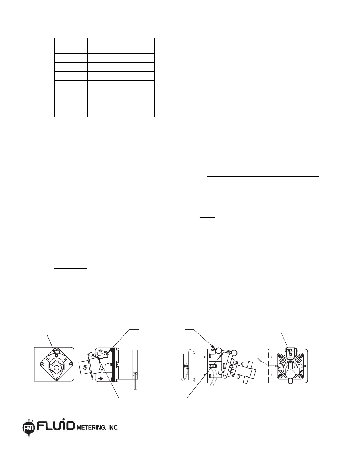
1.0 PUMP MOUNTING: For optimum pump per-
formance it is recommended that your FMI pump
be mounted in a vertical position with the pump
head down in a 6:00 o'clock position and the motor
at 12:00 o'clock.This orientation will allow air bub-
bles that enter the pumping chamber to directly exit
through buoyancy assistance. Figure A
SAFETY INSTRUCTIONS
ST431-02
Figure A
FOR ADDITIONAL REFERENCES SEE H431 AND Q431
!

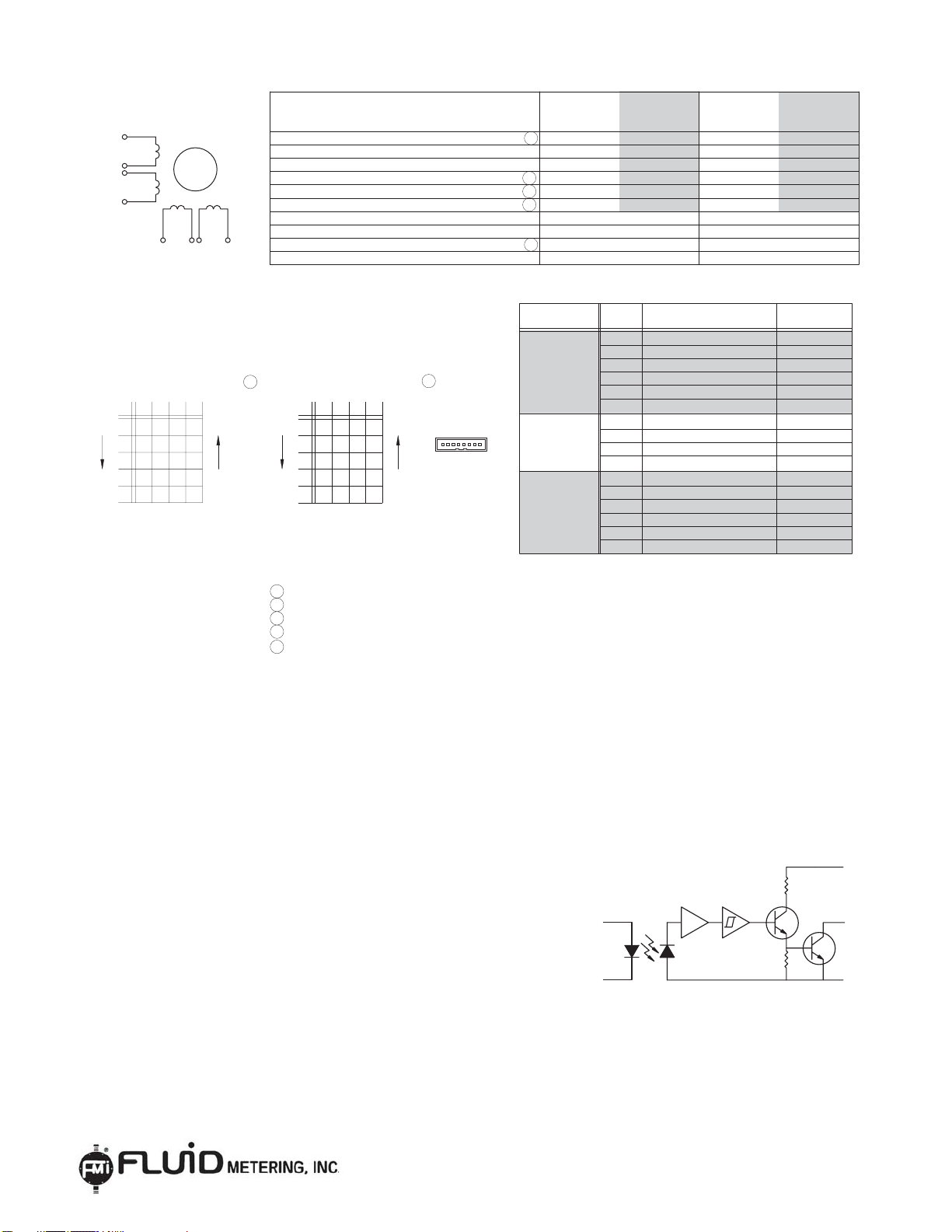
2.3 Step Motors:
FMI STH and STQ standard pumps are supplied
with a 23 frame, 1.8°/ step, hybrid 8 lead step motor.
For wiring diagram and detailed motor specifications
see Figure F
2.4 Rotational Sensor:FMI STH and
STQ standard pumps are supplied with an LED
rotational sensor. For wiring diagram and sensor
details see Figure G .
2.4.1 For sensor use with FMI SCST-01 Step
Motor Controller
see SCST-01 instructions.
3.0 CALIBRATION AND TESTING
3.1 Flush the system: clean with alcohol
or other suitable cleaning/wetting agent
before using the hydraulics and pump for the
first time. Prime pump with fluids to assure
system is free of air bubbles.
3.2 Place pump in the standard "home"
position with the piston-flat perpendicular to
the inlet port.The inlet port will be on the left
when the motor rotates clockwise (see
Figure B for the STH pump and Figure C for
the STQ pump).
OUTLET
STQ PISTON FLAT - SENSOR / FLAG
RELATIONSHIP TO INLET AND OUTLET PORTS
CLOCKWISE
MOTOR
ROTATION
PISTON
FLAT
PISTON
FLAT
INLET
CLOCKWISE
MOTOR
ROTATION
OUTLET
ADJUSTMENT
SCREW
FLAG
SENSOR
STH PISTON FLAT - SENSOR / FLAG
RELATIONSHIP TO INLET AND OUTLET PORTS
INLET
3.3 Check the pump's dispense volume by
cycling the pump for one complete 360°
revolution (one complete rotation). Dispense onto
an analytical pan balance and observe the volume.
See Figure D. Readjust as necessary.
REMARK: When dispensing water-like solutions
assume 1 ml = 1 gram. A correction factor will
be required for other fluids.
PAN BAL
A
INLET OUTLET
WATER SUPPLY
CLOCKWISE
ROTATION
Figure B Figure C
Figure D
pan Balance
2
5 Aerial Way, Suite 500, Syosset NY 11791 Tel: 516-922-6050 Fax: 516-624-8261
ST431-02
CAUTION:
DO NOT ATTEMPT TO LOOSEN "LOCK NUT", THIS WILL RESULT IN
BREAKING THE ADJUSTMENT SCREW.
STH PUMPS STQ PUMPS
ADJUSTMENT
SCREW
LOCK ADJUSTMENT
(REMOVABLE THREAD LOCK)
ADJUSTMENT
SCREW
HEX LOCK NUT
DO NOT
LOOSEN
3.4 Dispense Volume Values for FMI
STH/STQ Pumps:
NOTE: To assure the best performance set the pump
displacement volume as large as possible. FMI pumps
are calibrated at the factory to the maximum value.
Both STH and STQ pumps can be adjusted down to as
little as 10% of the rated flow.
3.5 Adjusting Dispense Volumes:
To adjust dispense volumes rotate the stroke-length
adjustment screw using the appropriate hex driver
(see Required Tools on page 1). To increase the flow,
turn the screw counter-clockwise. To decrease the
flow, turn the screw clockwise
CCW=Increase, CW=Decrease.
CAUTION: DO NOT LOOSEN THE HEX LOCK
NUT WHEN ADJUSTING THE STROKE RATE. IT IS
SET AT THE FACTORY AND SHOULD NOT BE
TAMPERED WITH. See Figure E
3.6 Lock setting: Once the pump is calibrated apply
a drop of removable wicking thread lock between the
lower pivot pin and the adjustment screw threads.
See Figure E.
3.7 Dispensing Hints:
1) Speed - Optimum results for fluids 500 cps or
less is between 120-350 rpm.
2) Cavitation: Use the largest suction tubing you
can to avoid cavitation.
3) Splashing can usually be avoided by
modifying dispense tip to larger I.D.and/or
decreasing dispense speed.
4) Hanging drop at dispense tip can be avoided by:
a) Use of rigid discharge tubing
b) Small dispense tip
c) Increasing speed
5) High viscosity dispensing requires:
a) Large suction tubing
b) Pressurizing suction reservoir
6) Bubbles in discharge
a) Suction fitting leak
b) Cavitation
7) Need Help? Call, fax, or email us… We can
help solve almost any fluid control problem.
3.8 SPECIAL MOTORS AND CONTROLLERS
FMI offers a complete variety of stepper motors
and stepper motor controllers from simple quick
start control to complex application specific stepper
motor control. Our standard step motor controllers
are:
SCST General Purpose Stepper Motor Control for
quick start control of FMI STH and STQ pumps.
ICST Intelligent Stepper Motor Controller
which includes an embedded microprocessor for
custom programming of FMI stepper motor pumps
to meet specific application operations.
IDS 2000 Industrial Dispenser/Pump which includes
the SCST and FMI pump head integrally mounted
in a rugged stainless steel enclosure.
STH00 0.002 0.025
STH0 0.005 0.050
STH1 0.010 0.100
STQ0 0.008 0.080
STQ1 0.003 0.032
STQ2 0.007 0.072
STQ3 0.128 1.280
NOTE:FOR ADDITIONAL REFERENCES SEE H431 AND Q431
Figure E
3
MODEL ML/REV
MIN
ML/REV
MAX
5 Aerial Way, Suite 500, Syosset NY 11791 Tel: 516-922-6050 Fax: 516-624-8261
ST431-02
PIN 3
PIN 7
PIN 4
BLU
BRN
ORG
GRN
PIN 8
PIN 1
PIN 5
PIN 2
YEL
WHT
BLK
RED
PIN 6
5 INDICATED DIRECTION WHEN VIEW FROM MOTOR DRIVE SHAFT END.
4 SUGGESTED MATING CONNECTOR AMP# 640620-8 OR EQUIVALENT.
3 SMALL SIGNAL INDUCTANCE AS MEASURED AT WITH IMPEADENCE BRIDGE @ 1 KHZ, 1 AMP.
2 WINDINGS AT 130°C MOTOR UNMOUNTED IN STILL AIR AT 40°C (AMBIENT).
MOTOR VALUE DATA ALL VALUES TYPICAL AT
P/N 641653-8
AMP CONNECTOR
GND = GROUND
O = OFF OR OPEN
- = NEGATIVE FLOW
+ = POSITIVE CURRENT FLOW
0
GND
0
GND
GND
0
0
GND
0GND
0GND
GNDGND 0
GND 0
5
DRIVER CONNECTION
C
CCW
0
A
0
GND
2
1
CW
STEP
3
4
1
UNIPOLAR FULL STEP
PHASE SEQUENCING
BD
CCW
CW
5
PHASE SEQUENCING
BIPOLAR FULL STEP
DRIVER CONNECTION
+--+
-+-+
-++-
-+-+
+--+
1
4
3
2
1
BBAA
STEP
1 WITH RATED CURRENT APPLIED.
NOTES:
STEP ANGLE
8-LEAD CONFIGURATION
RTH THERMAL RES , WINDINGS TO AMBIENT
Jm ROTOR INERTIA
Td DETENT TORQUE
Tr LOW SPEED RUNNING TORQUE
40° C UNLESS OTHERWISE NOTED
Tr LOW SPEED RUNNING TORQUE
Th HOLDING TORQUE (2-PHASE ON)
Lp PHASE INDUCTANCE
Rp RESISTANCE: 25°C
Ke VOLTAGE CONSTANT/PHASE
IC RATED CONT. CURRENT/PHASE IN AMPS
A
RED
6
B
A
6
1YEL
RED
C
+V
D
+V
8
3
2 & 5
4 & 7
BLU
GRN
ORG & BRN
BLK & WHT
6-LEAD
UNIPOLAR
6 & 5 A
RED & WHT
A
B
B
1 & 2
8 & 7
3 & 4
YEL & BLK
GRN & BRN
BLU & ORG
PARALLEL
BIPOLAR
4-LEAD
COMMON
COMMON
B
B
A
ORG & BRN
BLK & WHT
BLU
GRN
YEL
4 & 7
2 & 5
3
8
1
SERIES
BIPOLAR
4-LEAD
LEAD
COLOR CONNECTION
DRIVER
PIN
CONNECTION
1.8
DEGREES OF ROTATION
2
1
1
3
2
-3
2
2
5.5
DEGREES C PER WATT
0.0017 (0.012)
OZ-IN-SEC (KG-M 10 )
4.0 (0.028)
OZ_IN (Nm)
OZ_IN (Nm) 89 (0.63) 63 (0.44)
82 (0.58)
2.3
1.06
0.206
2.5
89 (0.63)
116 (0.82)
2.3
0.53
0.206
3.5
89 (0.63)
116 (0.82)
9.2
2.12
0.412
1.75
OZ_IN (Nm)
OZ_IN (Nm)
mH
OHMS
Vpk/RAD/SEC
AMPS
UNIPOLAR
6-LEADPARALLEL
SERIES
UNITS
FMI STEP MOTOR 23 FRAME PART NO. 110746
* USE FOR BEST PREFORMANCE
*
FIGURE B
BIPOLAR
4-LEAD
BIPOLAR
4-LEAD
LA
WHITE
BLUE
GREEN
RED
BLACK
(OPEN-COLLECTOR OUT-
PUT)
INVERTER
Absolute Maximum Rating (TA=25ºC Unless otherwise noted)
Supply voltage, V(not to exceed 3sec.).......................10 V
Input diode power dissipation....................................100 mW (1)
Output power dissipation............................................200 mW2)
Total device power dissipation....................................300 mW (3)
Voltage at output lead (open collector output)............35 V
Diode foreword D.C Current............................................40 mA
Diode reverse D.C Voltage.............................................2 V
Note:
1. Derate linearly 2.22mW / ºC above 25ºC
2. Derate linearly 4.44mW / ºC above 25ºC
3. Derate linearly6.66mW / ºC above 25ºC
4. The optical switches are terminated with 24 inches
of 26 A.W.G.,UL 1492 wire on each terminal.
Insulation colors and function are as follows:
Red-Anode, Black-Cathode, White-Vcc, Blue-Output, Green-Ground
5. Normal application would be used with light source blocked, simulated by1F=0mA
6. All parameters tested using pulse techniques.
Figure G
Figure F
5 Aerial Way, Suite 500, Syosset NY 11791 Tel: 516-922-6050 Fax: 516-624-8261
4
ST431-02
This manual suits for next models
6
Popular Water Pump manuals by other brands

Annovi Reverberi
Annovi Reverberi AR 40 Series instruction manual

Aquatec
Aquatec AQUAPRO AP1000FP instruction manual

Schmalz
Schmalz SXP Series operating instructions

Sulzer
Sulzer XFP PE1 Installation, Operating and Maintenance Instruction

Mueller
Mueller HYDRO GUARD HG-8 Standard User's operation manual

Gianneschi
Gianneschi MVG Use and maintenance manual


PSG Dover
PSG Dover All-Flo A050 Users installation operation & maintenance

Xylem
Xylem Flygt 5520 Installation, operation and maintenance manual

Barnes
Barnes 2ADE11 Installation and operation manual

Zoeller
Zoeller X71 Series owner's manual

Stark
Stark 72025 Owner's manual and safety instructions

Grundfos
Grundfos Unilift AP12 Installation and operating instructions