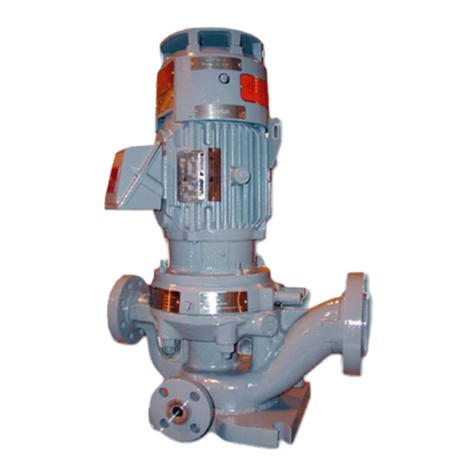
Sundyne LMV-806 Manual

SUNDYNE
LMV-806 PUMPS
Instruction and Operation Manual
August 2007
Visit our website at www.sundyne.com
SA-07-11-38, Rev Orig
Aug 2007

Copyright
All rights reserved. No part of this publication may be reproduced, stored in a retrieval system or transmitted in any form or by any means,
electronic, mechanical, photocopying, recording or otherwise without the prior permission of Sundyne Corporation.
© 2007Sundyne Corporation
Warranty
Sundyne Corporation warrants to Buyer for a period of twelve (12) months from the date of being placed in service (but not to exceed eighteen
(18) months after the date of shipment) that the equipment at the time of shipment will be free from defects of design, material and workmanship.
If any defects or malperformance occur during the warranty period, Sundyne’s sole obligation shall be limited to alteration, repair or replacement
at Sundyne’s expense, F.O.B. Factory, of parts or equipment, which upon return to Sundyne and upon Sundyne’s examination prove to be
defective. Equipment and accessories not manufactured by Sundyne are warranted only to the extent of and by the original manufacturers’
warranty. Sundyne shall not be liable for damage or wear to equipment caused by abnormal conditions, vibration, failure to properly prime or to
operate equipment without flow or caused by corrosives, abrasives or foreign objects. THE FOREGOING WARRANTY IS EXCLUSIVE AND
IN LIEU OF ALL OTHER WARRANTIES, WHETHER EXPRESSED OR IMPLIED INCLUDING ANY WARRANTY OF
MERCHANTABILITY OR FITNESS FOR ANY PARTICULAR PURPOSE. In no event shall Sundyne be liable for consequential or incidental
damages.
SA-07-11-38, Rev Orig
Aug 2007

SA-07-11-38, Rev Orig
Aug 2007

iv
INTRODUCTION & SAFETY
Equipment and Safety Precautions
Sundyne Corporation manufactures centrifugal
pumps to exacting International Quality
Management System Standards (ISO 9001) as
certified and audited by Lloyd’s Register Quality
Assurance Limited. Genuine parts and
accessories are specifically designed and tested
for use with these products to ensure continued
product quality and performance. Sundyne
cannot test all parts and accessories sourced
from other vendors; incorrect design and/or
fabrication of such parts and accessories may
adversely affect the performance and safety
features of these products. Failure to properly
select, install or use authorized Sundyne pump
parts and accessories is considered misuse and
damage or failure caused by misuse is not
covered by Sundyne’s warranty. Additionally,
modification of Sundyne products or removal of
original components may impair the safety of
these products and their effective operation.
CAUTION
Note: Sundyne pumps may handle
hazardous, flammable, and/or toxic
fluids. Proper personal protective
equipment should be worn. Precautions
must be taken to prevent physical
injury. Pumpage must be handled and
disposed of in accordance with
applicable environmental regulations.
CAUTION
Note: Safety procedures must be applied
prior to any installation, maintenance,
or repair of a Sundyne pump. Failure to
follow safety precautions may lead to
injury!
Wearing Personal Protective
Equipment
To ensure safety, protective equipment must be
worn at all times when installing, performing
maintenance, or repairing equipment. The
following safety recommendations must be
adhered to for optimum safety:
• Safety glasses, with the minimum
requirement of side shields, must be worn
at all times.
• Steel-toed shoes must be worn when
lifting equipment greater than 15 pounds
(7 kg) or if pallet jacks or forklifts are
operated.
• Hearing protection is strongly
recommended at all times when noise
levels exceed 85 dB during an eight (8.0)
hour period.
CAUTION
Note: Chemical resistant gloves must be used
if chemicals are utilized (refer to Using
Chemicals for additional information).
CAUTION
Note: A dust mask respirator must be worn if
chemicals have warning labels
regarding fumes, dust, or mists.
When using more than one piece of protective
equipment, consider their compatibility. For
example, safety glasses will not interfere with
hearing protection equipment. Be sure to clean
all pieces of personal protective equipment
immediately after each use.
SA-07-11-38, Rev Orig
Aug 2007

v
Using Forklifts
Any persons operating a forklift must have an
active recognized operator license.
CAUTION
Note: Before initializing forklift operation,
verify that the lift is in a safe operating
position.
Ensuring Electrical Safety
All electrical sources must be powered-off
before installation, service, or repair of
equipment occurs.
CAUTION
Note: Sundyne recommends that a Lock-
out/Tag-out program be followed prior
to altering the equipment. Locks or
tags must be provided to warn
employees that equipment is
temporarily unavailable.
Once all work has been completed, the person
installing the lock or tag must remove it
according to company procedure.
Testing Equipment
Prior to performing a test on newly installed,
maintained, or repaired equipment; all personnel
in the immediate area must be warned.
CAUTION
Note: Follow company procedures prior to
equipment testing at all times.
Using Chemicals
Any chemicals to be used must be accompanied
by a relevant material safety data sheet (MSDS),
in accordance with government legislation. If
applicable, use chemical proof gloves.
CAUTION
Note: An eye wash station (or equivalent)
should be available in the event of
injury. If any hazardous or flammable
chemicals pass through the equipment,
a complete decontamination of the
equipment is required.
Protection from Falling
Fall protection and associated preventative
measures is required when working on
equipment located six feet or higher from the
ground.
CAUTION
Note: Follow company fall prevention
procedures prior to working on
equipment.
Preventative Machine Guards
Preventative guards must remain in place on all
equipment.
CAUTION
Note: Only remove the guards while
performing maintenance or repair.
Replace the guards immediately after working
on the equipment and prior to start up.
CAUTION
EXPLOSION/FIRE HAZARD
Never use an acetylene torch, open flame, or
heat to attempt to remove parts that have seized
together in Sundyne equipment. Any residual
process gas or liquid that is flammable can
result in an explosion or fire with potential for
serious injury or death.
CAUTION
SA-07-11-38, Rev Orig
Aug 2007

INTRODUCTION
This manual presents installation, servicing, troubleshooting, maintenance and spare parts information for the
Sundyne Model LMV-806 centrifugal pump.
If the pump has a bearing box and coupling option, the instructions for these are in a separate manual.
Parenthetical numbers included in the text correspond to item numbers of the illustrated figures. The item number
of a part is based on the part’s function and the correct spare part can be ordered for any generation pump even if
the component parts do not appear the same as presented in this revision of the instruction manual.
Information that may be required regarding performance, alterations, or detailed technical data which is not included
herein may be found in the specification sheet and parts list accompanying the unit, or may be obtained from your
Sundyne representative.
Custom-made auxiliary equipment cannot be shown in this manual. Refer to the outline drawing for specifics.
WARNING
The pump should not be operated, or maintenance performed, without a thorough understanding of the contents of
this manual.
1. INSPECTION
Care should be taken when uncrating the pump. If the
shipment is not delivered in good order and in accor-
dance with the bill of lading, note the damage or short-
age on both the receipt and freight bill. Make
any
claims to the transportation company immediately.
2. STORAGE
If the equipment is not to be installed immediately, it
should be stored in a clean, dry area. Care should be
taken to protect from exposure to moisture and dust.
Shipping covers installed at the factory for casing
flanges and seal ports must be kept securely in place.
Storage instructions provided by the driver (motor or
turbine) manufacturer should be observed.
If provisions for long term storage (periods in excess of
six months) are required and have not been made prior
to shipment of the unit, contact your Sundyne repre-
sentative for recommendations on storage procedures.
3. SUCTION AND DISCHARGE PIPING
A. All piping must be supported independently of the
pump. The piping should always line up with the pump
flanges. Never draw the piping into place by the use of
force at the flanged suction and discharge connections
as this may impose dangerous strains on the unit.
B. The piping, both suction and discharge, should be as
short and direct as possible. Avoid all unnecessary
elbows, bends, and fittings as they increase friction
losses in the piping. The size of the pipe and fittings
should be selected carefully and be of sufficient size to
keep the friction losses as low as practical.
C. If the pump is supported by the base, piping must not
be connected to the pump until after pump hold-down
bolts have been tightened.
D. The use of elbows near the suction flange should be
avoided. When used, elbows should be long radius. A
straight pipe run of at least two times the pipe diamete
r
is desirable between an elbow and the suction flange.
E. Suction pipe should never be of smaller diameter than
the pump suction inlet. Reducers, if used, should be
eccentric and preferably slope up to the pump to avoid
creating air pockets in the piping.
F. If reverse flow during shutdown is likely, it is recom-
mended that a check valve be installed in the discharge
line to protect the pump from possible reverse rotation.
4. SEAL ENVIRONMENTAL CONTROL SYSTEM
Depending upon the pump seal arrangement and
application, a seal environmental control system may
be required. The pump seal environment must always
be maintained as specified on the specification sheet
which accompanies each unit delivery. For many appli-
cations a standard kit can be supplied from the factory.
Insure that the seal environmental control system
specified is properly installed and that ports (refer to
Figure 1) are open or plugged as shown.
WARNING
PORT #1 MUST ALWAYS BE OPEN TO A DRAIN.
INSTALLATION
1
SA-07-11-38, Rev Orig
Aug 2007

SA-07-11-38, Rev Orig
Aug 2007

SA-07-11-38, Rev Orig
Aug 2007

SA-07-11-38, Rev Orig
Aug 2007

SA-07-11-38, Rev Orig
Aug 2007

SA-07-11-38, Rev Orig
Aug 2007

SA-07-11-38, Rev Orig
Aug 2007

SA-07-11-38, Rev Orig
Aug 2007

SA-07-11-38, Rev Orig
Aug 2007

SA-07-11-38, Rev Orig
Aug 2007

SA-07-11-38, Rev Orig
Aug 2007

SA-07-11-38, Rev Orig
Aug 2007

SA-07-11-38, Rev Orig
Aug 2007
STEP 13
STEP 14

Table 3. Torque Values
Gearbox
Sundyne Standard Steel Screws & Bolts and NACE Compliant Steel Screws/Bolts (BG Material)
Torque Values
Item # Location Size English Metric
905H Oil Filter Manifold 3/8 - 16 x 1/2 22 - 25 ft-lbs 30 - 34 N-m
905L Gearbox Seal 1/4 - 20 x 1/2 75 - 80 in-lbs 8.5 - 9.0 N-m
905M, N Journal Bearings #10 - 24 x 1 35 - 40 in-lbs 4.0 - 4.5 N-m
905T Chemical Barrier Gasket 1/4 - 20 x 5/8 75 - 80 in-lbs 8.5 - 9.0 N-m
909B Gearbox Halves 1/2 - 13 x4 60 - 65 ft-lbs 81 - 88 N-m
909C Gearbox Halves, Alignment 5/8 - 18 x 4 17/64 60 - 65 ft lbs 81 - 88 N-m
906B Sight Glass #8 - 32 x 1/2 10 - 12 in-lbs 1.0 - 1.4 N-m
Pumps & Compressors*
Sundyne Standard Steel Screws and Bolts
Torque Values
Item # Location Size English Metric
3 Impeller Bolt/Inducer:
LMV/BMP-801, 802, 806, 322, 311, 331 1/2 - 20 36 - 40 ft-lbs 49 - 54 N-m
LMV/BMP-341, 346 1/2 - 20 65 - 70 ft-lbs 88 - 95 N-m
LMV-313, 343, BMP-338, 348 (High Flow) 3/4 - 10 85 - 90 ft-lbs 115-122 N-m
LMC/BMC 3X1P, 3X1F, 3X3, 3X6P, 3X7 1/2 - 20 36 - 40 ft-lbs 49 - 54 N-m
906D Diffuser Attaching Screws 1/4 - 20 95 - 102 in-lbs 11 - 11.5 N-m
905E Mechanical Seal No. Spacer 1/4 - 20 x 12 95 - 102 in-lbs 11 - 11.5 N-m
905F Throttle Bushing/Mechanical Seal 1/4 - 20 x 12 9 5- 102 in-lbs 11 - 11.5 N-m
905G Double Seal with Spacer 1/4 - 20 x 3/4 95 - 102 in-lbs 11 - 11.5 N-m
914A Case Nuts 3/4 - 10 250 - 275 ft-lbs 340 - 375 N-m
914A Case Nuts 7/8 - 9 300 - 330 ft-lbs 405 - 445 N-m
905A Seal Housing to Gearbox 3/8 - 16 x 1 3/4 35 - 40 ft-lbs 47 - 54 N-m
905P Separator 1/4 - 20 x 5/8 95 - 102 in-lbs 11 - 11.5 N-m
Pumps & Compressors
NACE Compliant Steel Screws / Bolts (BG Material)
Torque Values
Item # Location Size English Metric
3 Impeller Bolt/Inducer:
LMV/BMP-801, 802, 806, 322, 311, 331 1/2 - 20 36 - 40 ft-lbs 49 - 54 N-m
LMV/BMP-341, 346 1/2 - 20 65 - 70 ft-lbs 88 - 95 N-m
LMV-313, 343, BMP-338, 348 (High Flow) 3/4 - 10 85- 90 ft-lbs 115 - 122 N-m
LMC/BMC 3X1P, 3X1F, 3X3, 3X6P, 3X7 1/2 - 20 36 - 40 ft-lbs 49 - 54 N-m
906D Diffuser Attaching Screws 1/4 - 20 70 - 75 in-lbs 8.0 - 8.5 N-m
905E Mechanical Seal No. Spacer 1/4 - 20 70 - 75 in-lbs 8.0 - 8.5 N-m
905F Throttle Bushing/Mechanical Seal 1/4 - 20 70 - 75 in-lbs 8.0 - 8.5 N-m
905G Double Seal with Spacer 1/4 - 20 70 - 75 in-lbs 8.0 - 8.5 N-m
914A Case Nuts 3/4 - 10 160 - 200 ft-lbs 217 - 270 N-m
914A Case Nuts 7/8 - 9 225 - 245 ft-lbs 305 - 332 N-m
905A Seal Housing to Gearbox 3/8 - 16 x 1 3/4 27 - 30 ft-lbs 47 - 54 N-m
905P Separator 1/4 - 20 x 5/8 70 - 75 in-lbs 8.0 - 8.5 N-m
* When using Teflon® o-rings, allow 15 minutes between torquing for the Teflon® to cold flow. Repeat torquing until there is no
change in torque.
MINIMUM REQUIRED PARTS AS A RESULT OF PUMP DISASSEMBLY
ITEM NO. PART NAME QTY.
87A Thermal Barrier 1
5 Impeller Tab Washer 1
936A "O" Ring 1
936F "O" Ring 1
936G "O" Ring 1
936H "O" Ring 1
(Seal Arrangement)
Single Double Tandem
936J "O" Ring 1 2 3
14
SA-07-11-38, Rev Orig
Aug 2007

15
PARTS LIST
1. GENERAL
Assemblies, subassemblies and components of
the Sundyne LMV-806 process pump are
illustrated in the following views and show the
basic features of a standard LMV-806 pump.
Refer to your Sundyne specification sheet for
those options applicable to your pump. The
corresponding parts list, keyed to each part by
item number, identify detail parts by name,
quantity and location.
2. RECOMMENDED SPARES
A recommended spare parts list is included on
page 22. There are 3 classes of recommended
spares. Each class requires various types and
quantities of spares based on the support of one
pump unit. The recommended spares are
classified depending upon equipment location,
type of service and operating conditions. An
available supply of spares provides immediate
replacement parts without costly downtime and
keeps inventory requirements to a minimum.
You can obtain assistance for planning an
adequate supply of recommended spare parts
from your Sundyne representative.
3. REPAIR KITS
Seal and o-ring repair kits are not illustrated
herein, but may be purchased directly from
Sundyne Corporation. The use of these kits
reduces maintenance time, prevents assembly
mistakes, simplifies stocking and inventory and
reduces delivery time.
4. ORDERING REPLACEMENT PARTS
When ordering replacement parts, give the
pump serial number and list each part by part
number as shown on the Parts List which is
supplied with each pump. This is the preferred
method. Otherwise, list each part by item
number (as listed in the illustrations) and part
name, with pump model and serial number.
Specify quantities desired.
Order parts from your Sundyne representative or
directly from Sundyne Corporation at the
address on the back cover.
SA-07-11-38, Rev Orig
Aug 2007
Table of contents
Other Sundyne Water Pump manuals

Sundyne
Sundyne LMV-313 Manual

Sundyne
Sundyne Sunflo P-3000 Series Installation instructions manual

Sundyne
Sundyne LMV-801 Manual

Sundyne
Sundyne LMV-802 Instruction manual

Sundyne
Sundyne LMV-803Lr Instruction manual

Sundyne
Sundyne LMV-333 Manual

Sundyne
Sundyne LMV-801S Instruction manual

Sundyne
Sundyne LMV-322 Manual
Popular Water Pump manuals by other brands

THE TRADING
THE TRADING MERCATO MEC-20 manual

Polygroup
Polygroup SUMMER WAVES SKIMMERPLUS F400C owner's manual

Power Team
Power Team PE55TWP-E110 operating instructions

Echo
Echo WP-1000 Operator's manual

Oerlikon Leybold Vacuum
Oerlikon Leybold Vacuum TURBOLAB 80 operating instructions

Jesco
Jesco MIDIDOS E Operation & maintenance instructions