Schmalz SXP Series User manual

Schmalz X-Pump –SXP / SXMP
DeviceNet
OperatingInstructions
Innovative Vacuum for Automation

Schmalz X-Pump OperatingInstructions
SCHMALZ
CONTENTS
1Safety Notes....................................................................................... 1-5
Symbols used in this manual.................................................................................. 1-5
Trademark - TM...................................................................................................... 1-5
General safety notes............................................................................................... 1-6
Use for the intended purpose.................................................................................. 1-6
2Description......................................................................................... 2-7
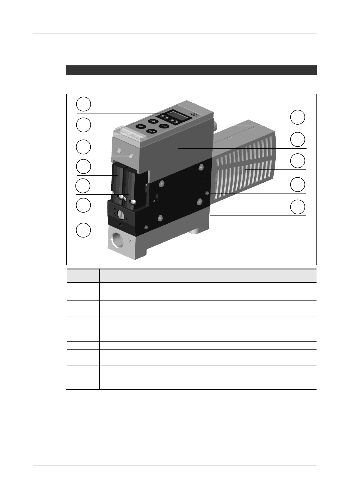
Overview of variants................................................................................................. 2-7
Basic module .......................................................................................................... 2-8
Expansion modules................................................................................................. 2-9
General functional description ................................................................................ 2-10
Putting into service................................................................................................... 2-11
Installation and operation........................................................................................ 2-11
Mounting................................................................................................................. 2-12
Electrical connections............................................................................................. 2-12
Pneumatic connections........................................................................................... 2-13
3Basic Settings.................................................................................... 3-15
Controls and Indicators........................................................................................... 3-15
Controls................................................................................................................... 3-16
Basic menu................................................................................................................ 3-17
Setting the threshold values [H-1], [h-1], [H-2], [h-2]............................................... 3-18
Setting the zero point (calibration) [CAL]................................................................ 3-19
PIN for basic menu [Pn1]........................................................................................ 3-20
Internal cycle counters [ct1], [ct2], [ct3]................................................................... 3-21
Displaying the internal counters.............................................................................. 3-22
Resetting the internal cycle counters...................................................................... 3-22
Leak detection function (LSF)................................................................................. 3-23
4Expert configuration ......................................................................... 4-24
Configuration menu [SEt], [out], [ctr], [t-1], [-L-], [bLo]............................................ 4-24
Unlocking the extended configuration menu........................................................... 4-25
Display settings......................................................................................................... 4-26
Setting the unit of measurement [uni]..................................................................... 4-26
Setting the reaction time......................................................................................... 4-26
Eco mode [Eco]....................................................................................................... 4-27
Setting the bus system options............................................................................... 4-27
PIN for the extended configuration menu [Pn2]...................................................... 4-28
Clearing all settings (clear all) [rES]........................................................................ 4-30
Outputs ...................................................................................................................... 4-31
Configuring the outputs [out]................................................................................... 4-31
Hysteresis mode –output type NO......................................................................... 4-33
Hysteresis mode –output type NC......................................................................... 4-33
Comparator mode –output type NO........................................................................ 4-34
Comparator mode –output type NC....................................................................... 4-34
Setting the reaction time [dLY]................................................................................ 4-35
Air saving and diagnostic functions....................................................................... 4-36

Schmalz X-Pump OperatingInstructions
SCHMALZ
Air saving functions [ctr] ..........................................................................................4-36
Air saving mode ON ................................................................................................4-37
Air saving mode ONS..............................................................................................4-38
Setting the permissible leakage [-L-].......................................................................4-38
Monitoring the evacuation time [t-1] ........................................................................4-40
Monitoring the valve switching frequency................................................................4-41
Diagnostic indicator.................................................................................................4-41
Diagnostic output.....................................................................................................4-42
Diagnosis and Analysis Function (DAF)..................................................................4-43
Blow-off functions.....................................................................................................4-44
Externally controlled blow-off [-E-]...........................................................................4-44
Externally controlled blow-off –time-dependent [E-t]..............................................4-44
Internally controllefd blow-off –time-dependent [l-t]................................................4-45
Setting the blow-off time..........................................................................................4-45
Meanings of the abbreviations in the display.........................................................4-46
5Bus System DeviceNet.......................................................................5-49
Statement of Conformance .....................................................................................5-49
Addressing (MAC ID) [Id] ........................................................................................5-49
Baud rate [bd]..........................................................................................................5-50
Termination .............................................................................................................5-51
Additional input and output......................................................................................5-51
Diagnosis.................................................................................................................5-52
DeviceNet protocol..................................................................................................5-53
Assignment of inputs and outputs...........................................................................5-55
EDS File ..................................................................................................................5-56
6Functional Description of the Ejector with Pulse Valve..................6-57
Voltage failure..........................................................................................................6-57
Control signals.........................................................................................................6-58
7Maintenance........................................................................................7-59
Warranty, spare parts and parts subject to wear ....................................................7-59
Spare parts and parts subject to wear ....................................................................7-60
Accessories.............................................................................................................7-60
8Possible Faults...................................................................................8-61
Troubleshooting.......................................................................................................8-61
Fault codes on the display.......................................................................................8-62
9Technical Data....................................................................................9-63
Electrical data ............................................................................................................9-63
Electrical connections..............................................................................................9-65
Mechanical data.........................................................................................................9-67
Dimensions..............................................................................................................9-68
Pneumatic diagrams................................................................................................9-70
Factory settings.........................................................................................................9-72
Declaration of Conformity ........................................................................................9-74

Schmalz X-Pump OperatingInstructions
1-4
SCHMALZ

Schmalz X-Pump OperatingInstructions
SCHMALZ
1-5
1 SAFETY NOTES
Symbols used in this manual
Danger
Danger
Identifies a hazard which may result in serious injuries to or even
death of persons.
Caution
Caution
Identifies a possibly hazardous situation which may result in minor
injuries to persons.
Identifies important information and notes.
Trademark - TM
The logo is a registered trademark of the ODVA
(www.odva.org).
In the following text, the system is referred to as "DeviceNet".

Schmalz X-Pump OperatingInstructions
1-6
SCHMALZ
General safety notes
These operating instructions contain important information about the use of
the ejector system. Please read them carefully and keep them in a safe
place for future reference.
Compressed air can cause closed containers to explode. Vacuum can
cause sealed containers to implode. The vacuum generator also generates
noise –it may be advisable to wear ear protectors!
If the ejector is used for other than its intended purpose (in other words, if it
is used to draw in hazardous dust, oil mist, vapours, aerosols, etc.), these
will be ejected with the exhaust air and may have negative effects on the
health of persons in the vicinity. Always use suitable and approved vacuum
filters.
Only the connection facilities, mounting holes and mounting elements pro-
vided by Schmalz may be used.
Always disconnect the supply voltage and the compressed-air supply before
installing or removing the ejector!
The components of the system may be used only by reliable persons who are
trained and familiar with, amongst other things:
the currently applicable safety regulations and requirements for the use of
the components and their controllers in machines and equipment (for sole-
noid valves, pressure switches, electronic controllers, etc.)
and the electrical control signals needed for them, such as redundancy and
any necessary feedback signals (for solenoid valves, pressure switches,
electronic controllers, etc.).
No persons may enter the area underneath the lifted load!
Use for the intended purpose
The ejector system serves to generate a vacuum and can be used to evacuate
such things as suction pads designed to grip loads or to evacuate vessels of
other kinds. It is approved for the evacuation of air or of other neutral gases in
accordance with EN 983.
The ejector system is not intended for the transport (extraction) of liquids or
granulates!
Caution
Caution

Schmalz X-Pump OperatingInstructions
SCHMALZ
2-7
2 DESCRIPTION
OVERVIEW OF VARIANTS
Each ejector has a precise article designation
(such as SXP 30 NO H 2xM12-5/8 DN PNP).
This article designation can be decoded as follows:
Type
Power
class
Idle position
Pneumatic
connections
Electrical
connections
Bus
system
Version
SXP
SXMP
with pow-
er blow-
off mod-
ule
15
20
25
30
NO
normally open
NC
normally closed
IMP
bistable,
switched by
pulse
H
horizontal
V
vertical
Q
quick-change
2xM12-5/8
2xM12,
5/8-pins
2xM12-5/4
2xM12,
5/4-pins
DN
DeviceNet
PNP
PNP-
switching
NPN
NPN-
switching
The ejector system consists of the basic module and various expansion mod-
ules. The main components are described below.
EJECTOR VARIANT NPN OR PNP
The different versions (PNP or NPN) apply only to units with additional input
and output (2xM12-5/8).
Depending on the variant, the inputs to the ejector are set to NPN or PNP and
cannot be changed! The outputs can be set to either NPN or PNP, as desired!
The factory settings are matched to the ejector variant.
NPN variant: inputs NPN (fixed) –outputs preset to NPN.
PNP variant: inputs PNP (fixed) –outputs preset to PNP.
For clarity, all specific information about the bus system DeviceNet is provided
in the section "Bus System DeviceNet".

Schmalz X-Pump OperatingInstructions
2-8
SCHMALZ
Basic module
The basic module of the ejector has the following components:
1
4
28
9
10
12
3
6
5
7
11
1
4
28
9
10
12
3
6
5
7
11
Item
Description
1
Display and controls
2
Diagnostic indicator
3
Valve-status indicator
4
Pilot valve "Blow off" - NC (normally closed)
5
Pilot valve "Vacuum on" - NO or NC, depending on the ejector variant
6
Throttle screw for blow-off volume flow
7
Vacuum connector G3/8“ (marked with "2[V]")
8
Electrical connector M12
9
Controller
10
Silencer
11
Mounting holes
12
Compressed-air connector
G3/8“ on H version, G1/4“ on V version (marked with "1[P]")

Schmalz X-Pump OperatingInstructions
SCHMALZ
2-9
Expansion modules
The basic module can be expanded and modified with many different expan-
sion modules:
3.4
3.3
4.1
3.2
3.1
2
1.1
1.2
1.3
4.2
3.5
3.4
3.3
4.1
3.2
3.1
2
1.1
1.2
1.3
4.2
3.5
Item
Description
1.1
Basic module –with suction valve NO... (normally open)
1.2
Basic module –with suction valve NC... (normally closed)
1.3
Basic module –with suction valve IMP... (bistable, switched by pulse)
2
Power blow-off module SXMP
3.1
Horizontal pneumatic connection block (1[P]= G3/8“, 2[V]= G3/8“)
3.2
Vertical pneumatic connection block (1[P]= G1/4“, 2[V]= G3/8“)
3.3
Quick-change pneumatic connection block
3.4
Dual quick-change pneumatic connection block
3.5
Quick-change unlocking lever
4.1
Electrical connections 1x M12, 5-pin, and 1xM12, 4-pin
4.2
Electrical connections 1x M12, 5-pin, and 1xM12, 8-pin

Schmalz X-Pump OperatingInstructions
2-10
SCHMALZ
General functional description
VACUUM GENERATION (GRIPPING)
The ejector is designed for the handling of parts with the aid of vacuum. With
the compressed-air supply connected, an external control signal (Suction on)
starts (NC ejector) or stops (NO ejector) vacuum generation by actuating an
integrated valve. The integrated sensor detects the actual system vacuum,
which is used for the display of the system states.
Depending on the selected air saving function, the electronic controller switches
off vacuum generation when the preset threshold value is reached. The safety
non-return valve prevents the loss of vacuum when handling workpieces with
smooth, airtight surfaces. If the system vacuum drops, as the result of leaks,
below the preset hysteresis value, vacuum generation is started again.
The ejector has various monitoring and diagnostic functions. For example, the
air saving function cycle is monitored and a suitable diagnostic signal is gener-
ated if this deviates from the permissible values. The available functions are
described in more detail in the following sections.
BLOWING OFF (RELEASING)
A second external signal (Blow off) injects compressed air into the vacuum cir-
cuit of the ejector systems to ensure that the vacuum drops quickly and the
workpiece can be released immediately.
In addition to direct control with the external blow-off signal, there are two fur-
ther blow-off functions. The first is where the desired blow-off duration is set in
the ejector system. An external signal at the input then initiates the blow-off op-
eration and this is terminated automatically after the preset time.
If the function "automatic blow-off" is selected, the blow-off operation is started
automatically when the external signal SUCTION OFF is applied (NO ejector) or
the external signal SUCTION ON is switched off (NC ejector). In each case, the
blow-off operation lasts for the period set in the ejector system. This means that
no additional signal is needed to release the workpiece.
Ejectors equipped with the power blow-off module (SXMP) may not be operated
with the vacuum connection closed.
VACUUM DISPLAY
The actual system vacuum is permanently displayed on the 3-digit display. The
currently selected unit of measurement can be displayed briefly by pressing the
<ENTER> key in display mode.
The four LEDs below the display show how the current vacuum level relates to
the threshold values set in the system.
Caution
Caution

Schmalz X-Pump OperatingInstructions
SCHMALZ
2-11
PUTTING INTO SERVICE
Installation and operation
Amongst other things, the following must be observed and complied with in or-
der to ensure correct installation and trouble-free operation of the ejector sys-
tem:
Carefully remove the components from their packing materials.
Take care that the components are not damaged during installation.
Disconnect the supply voltage and the compressed-air supply during instal-
lation and maintenance and ensure that they cannot be switched on inad-
vertently.
The system may be operated with a supply voltage provided only by a pow-
er supply unit which supplies a protective low voltage (PELV) and which en-
sures safe isolation from the mains voltage in accordance with EN60204.
The system may not be operated outside the specified performance limits,
since this may cause malfunctions or result in destruction of the system!
The system may not be operated in explosion-hazard areas, since this may
result in fire or explosions!
The components of the system may not be modified in any manner.
The connectors on the components are marked with symbols and designa-
tions, which must always be observed.
Only the standard connection facilities may be used.
Pneumatic lines and electric cables must be permanently connected to the
components and secured to prevent them from being pulled off.
Non-compliance with the above rules may result in malfunctions, in damage
to the system and even in (possibly fatal) injuries to persons.
The factory warranty no longer applies if the “tested” sticker is damaged.
If the ejector system is taken out of service, its components must be dis-
posed of in an environmentally friendly manner!

Schmalz X-Pump OperatingInstructions
2-12
SCHMALZ
Mounting
Read the safety notes carefully before mounting the ejector system!
INSTALLATION
The system may be installed in any desired orientation.
Use only suitably treated compressed air (with or without oil - see the tech-
nical data).
The quality of the compressed air is decisive for achieving the optimum op-
erating lifetime of the ejector systems.
Electrical connections
The supply voltage and signals are connected to the system via M12 male
connectors.
Depending on the configuration, the system has either one 5-pin male con-
nector and one 4-pin male connector or one 5-pin male connector and one
8-pin male connector. All connectors have M12 threads. The pin assign-
ments can be found in the section "Technical Data".
The system may be operated with a supply voltage provided only by a pow-
er supply unit which supplies a protective low voltage (PELV) and which en-
sures safe isolation from the mains voltage in accordance with EN60204.
MAXIMUM CABLE LENGTHS
Baud rate
Maximum cable length
500 kBit/s
100 m
250 kBit/s
250 m
125 kBit/s
500 m
Caution
Caution

Schmalz X-Pump OperatingInstructions
SCHMALZ
2-13
Pneumatic connections
Use large-diameter vacuum hoses up to a point as close as possible to the
suction pads!
Use only hoses and pipes with the recommended internal cross-sections
(see the table below). If this is not possible, use a hose or pipe with the next
larger internal cross-section.
Make sure that there are no particles of dirt or other foreign bodies in the
system connectors or the hoses.
The use of a hose or pipe with an insufficient internal cross-section on the
compressed-air side will prevent the system from receiving enough com-
pressed air for optimal operation.
Hoses or pipes with insufficient internal cross-sections on the vacuum side
will cause excessive flow resistance along the walls of the hose or pipe, and
this will have negative effects on the suction capacity and the evacuation
times. The high flow resistance will result in longer blow-off times.
Hoses should be kept as short as possible in order to minimise the reaction
times of the system.
Ensure that the hoses are not kinked or pinched.
RECOMMENDED CROSS-SECTIONS (INTERNAL DIAMETERS)
SXP/ SXMP
power class
Cross-section (internal diameter) [mm]1)
Compressed-air side
Vacuum side
15
6
6
20
6
8
25
8
9
30
8
9
1) These values apply to hoses with a maximum length of 2 metres
OPERATING MEDIUM
Air or neutral gas, filtered (pore size 50µm), with or without oil

Schmalz X-Pump OperatingInstructions
2-14
SCHMALZ
MOUNTING THE DUAL QUICK-CHANGE BLOCK
When mounting the ejector SXP/SXMP...Q on a quick-change system, always
proceed in the following order:
Press the unlocking lever fully downwards and hold it there.
Position the ejector correctly on the quick-.change system with the aid of the
centring pin and push it fully downwards.
Release the unlocking lever so that it returns to its normal position.
The ejector system may be operated only with the unlocking lever fully extend-
ed and with the ejector correctly locked into position.
Always turn off the compressed-air supply before actuating the unlocking lever
of the quick-change system!
ADJUSTING THE BLOW-OFF VOLUME FLOW
The throttle screw located below the pilot valves can be used
to adjust the blow-off volume flow.
Turing this screw clockwise reduces the volume flow, turning
it counter clockwise increases it.
The throttle screw is equipped with stops at each end of its
permissible travel.
Never attempt to turn the throttle screw past its stops! For technical reasons,
there must always be a certain minimum volume flow, which means that the
flow cannot be reduced to zero!
Danger
Danger
Caution
Caution
Caution
Caution
+-
+-

Schmalz X-Pump OperatingInstructions
SCHMALZ
3-15
3 BASIC SETTINGS
Controls and Indicators
The EJECTOR can be set and operated very easily with the aid of the foil key-
pad with three-digit display and the four additional LEDs.
If any settings are changed, incorrect system states may possibly occur for a
brief period (about 50 ms).
1
2
3
4
5
6
1
2
3
4
5
6
1
Display
2
LEDs
3
MENU key
4
ENTER key
5
UP key
6
DOWN key
Caution
Caution

Schmalz X-Pump OperatingInstructions
3-16
SCHMALZ
Controls
In the basic state (display mode), the current system vacuum is permanently
displayed. In this mode, the keys have the following functions:
The operating structure is divided into a basic menu and a configuration menu.
For standard applications, all necessary settings of the ejector can normally be
made in the basic menu. The extended configuration menu is available for ap-
plications with more demanding requirements.
Opens the basic menu (threshold settings, etc.)
> 3 sec
> 3 sec
Opens the configuration menu
Displays the maximum recorded vacuum value (since connec-
tion of the supply voltage)
Displays the minimum recorded vacuum value (since connec-
tion of the supply voltage)
Shows the unit of measurement in which the vacuum is cur-
rently displayed

Schmalz X-Pump OperatingInstructions
SCHMALZ
3-17
BASIC MENU
The basic menu can be used to make all necessary settings for standard appli-
cations of the ejector and to display the current settings.
blinking
blinking
blinking
blinking
blinking
Set the value Value blinks as
confirmation
go to
go to
go to
go to or
go to
Unit = [10ms]
blinking
1st digit
blinking blinking
> 3s
blinking
blinking
blinking
blinking
blinking
Set the value Value blinks as
confirmation
go to
go to
go to
go to or
go to
Unit = [10ms]
blinking
1st digit
blinking blinking
> 3s
The function [tbl] is active only if one of the two time-controlled blow-off func-
tions has been selected. For further details, see the section "Bow-off functions".
Depending on the setting of the output function (hysteresis or comparator),
"H/h" or "C/c" is displayed when setting the threshold values.

Schmalz X-Pump OperatingInstructions
3-18
SCHMALZ
H1
Deactivation value for air-saving
function
H2
Activation value of output of part pre-
sent
h1
Hysteresis of air-saving function
h2
Hysteresis of output of part present
H1-h1
Activation value for air-saving
function
H2-h2
Deactivation value of output of part
present
Setting the threshold values [H-1], [h-1], [H-2], [h-2]
The order of the parameters in the menu is shown in the diagram above.
Press the <MENU> key.
If the menu is locked, enter the appropriate PIN.
Use the <UP>or <DOWN> key to select the desired parameter.
Press <ENTER> to confirm the selection.
Use the <UP>or <DOWN> key to change the value.
Press the <ENTER> key to save the new setting.
The next parameter is now displayed automatically.
The four yellow LEDs below the display show which value is currently being set.
If the <UP>or <DOWN> key is pressed and held, the value to be changed is
incremented rapidly.
If you exit from the menu by pressing the <MENU> key after changing a value,
the new value is not saved.

Schmalz X-Pump OperatingInstructions
SCHMALZ
3-19
Setting the zero point (calibration) [CAL]
For adjustment of the zero point, the vacuum circuit of the system must be
vented (to the atmosphere).
Press the <MENU> key.
If the menu is locked, enter the appropriate PIN.
Press the <UP>or <DOWN> key several times until [CAL]appears in
the display.
Press the <ENTER> key to confirm the selection.
The display then blinks briefly and returns automatically to the display mode.
A zero-point offset is possible only within the range 3% of the full-scale value.
In other words, the zero point can be shifted by up to 30 mbar from the original
zero point.
If you exceed the permissible range of 3%, the error code E3 appears in the
display.

Schmalz X-Pump OperatingInstructions
3-20
SCHMALZ
PIN for basic menu [Pn1]
The basic menu can be locked with PIN [Pn1] to prevent unauthorised access.
The extended configuration menu can also be locked, regardless of whether or
not the basic menu is locked.
When the system leaves the factory, the PIN is set to 000, which means that
the basic menu is not locked. In order to lock it, you must enter a valid PIN be-
tween 001 and 999.
DEFINING THE PIN
Press the <MENU> key.
If the menu is locked, enter the appropriate PIN.
Press the <UP>or <DOWN> key several times until [Pn1] appears in
the display.
Press the <ENTER> key to confirm the selection.
Use the <UP>or <DOWN> key to set the first digit of the desired PIN.
Press the <ENTER> key to confirm the selection.
Enter the second and third digits of the desired PIN in the same manner.
Press and hold the <ENTER> for at least three seconds to save the
PIN.
The PIN you have entered blinks briefly in the display and the basic menu is
closed.
To open the basic menu after definition of a PIN, press the <MENU> key and
enter the PIN in the manner described above.
If you have forgotten the correct PIN, the PIN for the basic menu [Pn1] can be
reset to its default value of 000 by resetting all settings with the function [res]
in the configuration menu!
If an incorrect PIN is entered, the message [Loc]is displayed and the menu
remains locked!
This manual suits for next models
9
Table of contents
Other Schmalz Water Pump manuals

Schmalz
Schmalz EVE-TR 60 AC3-F User manual

Schmalz
Schmalz EVE-OG 10 User manual

Schmalz
Schmalz EVE-TR-M User manual

Schmalz
Schmalz Blower Box SBB Manual

Schmalz
Schmalz EVE-OG 25 User manual

Schmalz
Schmalz EVE Guide

Schmalz
Schmalz EVE-TR 250 AC3-F User manual

Schmalz
Schmalz SXP User manual

Schmalz
Schmalz SCPMi Series User manual

Schmalz
Schmalz CobotPump ECBPi User manual